
Related Manuals for Austin Hughes Infra Cool CMS-03-S


Summary of Contents for Austin Hughes Infra Cool CMS-03-S
- Page 1 Rack Airfl ow Control User Manual CMS-03-S , Master IP Fan unit GUI & SNMP Designed and manufactured by Austin Hughes UM-CMS-03-S-Q121V1 www.austin-hughes.com...
- Page 2 Legal Information First English printing, February 2021 Information in this document has been carefully checked for accuracy; however, no guarantee is given to the correctness of the contents. The information in this document is subject to change without notice. We are not liable for any injury or loss that results from the use of this equipment.
- Page 3 Unpacking The equipment comes with the standard parts shown on the package contents. Check and make sure they are included and in good condition. If anything is missing, or damage, contact the supplier immediately. UM-CMS-03-S-Q121V1 www.austin-hughes.com...
- Page 4 Content Part I. Installation < 1.1 > 1U Fan Tray < 1.2 > 33U Door Mount Fan Panel Part II. Hardware < 2.1 > Key Features < 2.2 > Fan Kit Specifi cation < 2.3 > Master IP Fan Unit Model & Specifi cation ( 1U Fan Tray with 6 fans ) MRF-1.6 ( 1U Fan Tray with 9 fans )
- Page 5 P.21 Part III. Software < 3.1 > Key Features < 3.2 > Master IP Confi guration < 3.3 > CMS-03-S Master IP Fan Unit GUI < 3.4 > SNMP Setup < 3.5 > Master IP Fan Unit Firmware Upgrade < 3.6 > DHCP Setting UM-CMS-03-S-Q121V1 www.austin-hughes.com...
-
Page 6: Installation
< Part I > Installation < 1.1 > 1U Fan Tray Package Content - 1U rackmount fan tray x 1 pc - Temp. sensor x 1 pc - 6 ft power cord x 1 pc - Rear mounting bracket x 1 pair * M6 screws for fi... -
Page 7: Package Content
< 1.2 > 33U Door Mount Fan Panel MRF-33.9 & RF-33.9 Door mount Fan Panel are typically installed on the outside of a rack’s rear perforated door to improve extraction of heat from high density rack. The unit can be attached to most 42U or taller racks. If aisle is relatively narrow for exterior mounting, the unit may be installed on the inside of the perforated door. -
Page 8: Installation Steps
< 1.2 > 33U Door Mount Fan Panel Caution - Power off the fans if the door is to be opened for maintenence or service of items within the rack. The fans have fi nger guards but care must be excerised when working around spinning fans. - Page 9 < 1.2 > 33U Door Mount Fan Panel Air Blocking Material To eliminate bypass air to maximize heat removal from the rack, cut the air blocking material to the size necessary with cutter or scissors, and then apply the material to the inside surface of the door with magnets or double sided adhesive tapes. Ensure all open perforations are covered by the material.
-
Page 10: Hanging Bracket Installation
< 1.2 > 33U Door Mount Fan Panel Hanging bracket installation Assemble & adjust the hanging bracket with M4*6mm screw & nut, to fi t the thickness of the door. Install the hanging bracket kit on the rear side of the fan panel with M4*10mm screw. Hang the unit on the door. - Page 11 < Part II > Hardware < 2.1 > Key Features Intelligent Intelligent Master IP Expansion Serial Fan Unit Fan Unit Daisy Chain Position 1st Level 2nd - 16th Level IP Port Daisy Chain Port - LINK Daisy Chain Port - OUT Temp.
- Page 12 < 2.2 > Fan Kit Specifi cation Air Delivery : 108 CFM Rated Speed : 3000 rpm, +/-10% Rated Voltage : 12V DC Rated Current : 350 mA Noise Level : 41 dB Dimension : 120 x 120 x 25 mm Bearing System : Dual ball bearing UM-CMS-03-S-Q121V1...
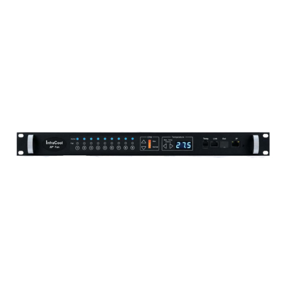
- Page 13 < 2.3 > Master IP Fan Unit Model Model : MRF-1.6 1U Fan Tray with 6 fans - Unit CFM Status LED - Unit CFM Setting - Individual fan status - Buttons for Alarm - Individual fan On / Off buttons Temp.
- Page 14 < 2.3 > Master IP Fan Unit Model Model : MRF-1.9 1U Fan Tray with 9 fans - Unit CFM Status LED - Unit CFM Setting - Individual fan status - Buttons for Alarm - Individual fan On / Off buttons Temp.
- Page 15 < 2.3 > Master IP Fan Unit Model Model : MRF-33.9 33U Door Mount Fan Panel with 9 fans Front View Side View Top View 195 mm 42.9 mm 195 mm TEMP Link - Temp. port bundled w/ a temp. sensor - Daisy chain port for connecting to the Out port of the 2nd level fan unit - 1000Base-T ( Gigabit ) IP port for remote...
- Page 16 < 2.3 > Master IP Fan Unit Specifi cation Table Model MRF-1.6 / 1.9 MRF-33.9 Master IP Fan No. of Fan 6 / 9 Mounting Door mount CFM Level Normal / High / Max. Individual Fan ON / OFF Individual Fan CFM 108 CFM Unit CFM ( Approximately ) 324 / 648 / 972 CFM...
- Page 17 < 2.4 > Expansion Serial Fan Unit Model Model : RF-1.6 1U Fan Tray with 6 fans - Unit CFM Status LED - Unit CFM Setting - Individual fan status - Buttons for Alarm - Individual fan On / Off buttons Temp.
- Page 18 < 2.4 > Expansion Serial Fan Unit Model Model : RF-1.9 1U Fan Tray with 9 fans - Unit CFM Status LED - Unit CFM Setting - Individual fan status - Buttons for Alarm - Individual fan On / Off buttons Temp.
- Page 19 < 2.4 > Expansion Serial Fan Unit Model Model : RF-33.9 33U Door Mount Fan Panel with 9 fans Front View Side View Top View 195 mm 42.9 mm 195 mm TEMP Link - Temp. port bundled w/ a temp. sensor - Daisy chain Link port for connecting to the Out port of the 2nd level fan unit - Daisy chain Out port for connecting to the...
- Page 20 < 2.4 > Expansion Serial Fan Unit Specifi cation Table Model RF-1.6 / 1.9 RF-33.9 Expansion Serial Fan No. of Fan 6 / 9 Mounting Door mount CFM Level Normal / High / Max. Individual Fan ON / OFF Individual Fan CFM 108 CFM Unit CFM ( Approximately ) 324 / 648 / 972 CFM...
-
Page 21: Daisy Chain Connection
< 2.5 > Daisy Chain Connection ■ Only Master IP Fan Unit built-in IP remote access module ■ Master IP Fan unit MUST be set on the 1 daisy chain level ■ Please follow the steps below the set the daisy chain level for Master IP Fan unit & expansion fan units ■... - Page 22 < 2.5 > Daisy Chain Connection Remarks : ■ Each Master IP group supports 16 daisy chain levels. ■ The 1st level fan unit must be one of the Master IP fan unit models. ■ 1 x Master IP fan unit allows access to 16 levels. ■...
-
Page 23: Temperature Sensor
< 2.6 > Audio Temperature Alarm Setting Please follow the steps below to setup each FAN unit audio alarm Step 1. Press and hold the “ “ button for 5 seconds. Step 2. Press arrow button to enable / disable the audio alarm If enable the audio alarm, the buzzer will sound when the outside temperature is over the preset alarm temperature. - Page 24 < 2.7 > Temperature Sensor Temp. Sensor Part no. IG-T01 Range Temperature 0 to 80°C ( 32 to 176°F ) Sensitivity Accuracy ±1°C ( ±2°F) Resolution 0.1°C ( 0.2°F ) Response Time 5 to 30 sec Power Voltage 12VDC, powered by sensor port Requirement Current Consumption 20mA...
-
Page 25: Alarm Temperature Setting
< 2.8 > Alarm Temperature Setting How to set alarm temperature : ■ Hold for 5 seconds. ■ Press button to set the alaram temperature. The alarm temp. can be set either by these buttons or software. How to set temp. unit ( Celsius or Fahrenheit ) : ■... -
Page 26: Key Features
< 3.1 > Key Features InfraCool Manager CMS-03-S is a FREE built-in GUI of each Master IP Fan unit to remotely monitor the connected Expansion Serial Fan units. ( max. up to 16 fan units ) InfraCool Manager CMS-03-S Features Capacity Master IP group ( Just 1 IP for 16 fan unit levels ) Expansion Serial Fan unit number... - Page 27 < 3.2 > Master IP Confi guration Please take the following steps to confi gure the Master IP fan unit : 1. Prepare a notebook computer to download the IP setup utilities from the link : http://www.austin-hughes.com/support/utilities/infracool/IPSetupUtilities.msi 2. Double click the IPSetupUtilities.msi and follow the instruction to complete the installation.
- Page 28 < 3.3 > CMS-03-S Master IP Fan Unit GUI Each Master IP Fan Unit provides a FREE built-in GUI, CMS-03-S, which allows user, via a web browser, to see and manage the Intelligent Fan Unit’s data remotely over a TCP / IP Ethernet network. Each web browser window supports only one Master IP Fan Unit.
- Page 29 < 3.3 > CMS-03-S Master IP Fan Unit GUI In < Details >, - Change “ Rack “ and “ Position “ of Fan Unit and Click “ Apply “ to fi nish the settings. - Switch ON / OFF Fan Unit - Switch ON / OFF individual Fan - Change Fan Unit CFM - Click “...
- Page 30 < 3.3 > CMS-03-S Master IP Fan Unit GUI In < Temp. Setting >, - “ Activate “ or “ Deactivate “ Temp. sensor - Change “ Location “ , “ Alarm Setting “ & “ R. alert setting “ of Temp. sensor - “...
- Page 31 < 3.3 > CMS-03-S Master IP Fan Unit GUI In < System >, - Change Master IP Fan Unit name & location - Change temperature unit displayed in UI - Set the “ Date & Time “ of the Master IP Fan unit ( by “ Manually “ or “ NTP server “ ). Default is “...
- Page 32 < 3.3 > CMS-03-S Master IP Fan Unit GUI In < Network >, you can view the current IP setting of Master IP Fan unit and allows changing of these parameters. < LAN settings > Enter “ IPv4 address “ , “ IPv6 address “ , “ Subnet mask “ , “ Gateway “ ( For static IP setting only ) Enter the IP address of “...
- Page 33 < 3.3 > CMS-03-S Master IP Fan Unit GUI In < Login >, you can login the Master IP Fan unit by “ Local user “ or “ Domain/LDAP “ login. Default login : Local User - Change “ Login name “ - Enter “...
- Page 34 < 3.3 > CMS-03-S Master IP Fan Unit GUI - In “ Domain User Access “, - Enter “ Password “ of administrator - Click “ Update user list “ to update domain user list - Assign access right ( No access / Allow / Deny ) to “ User “ and Click “ Apply “. - The user assigned “...
- Page 35 < 3.3 > CMS-03-S Master IP Fan Unit GUI In “ Domain Users Access “, - Enter “ Password “ of administrator - Click “ Update User list “ to update domain group list - Assign access right ( No access / Allow / Deny ) to “ Group “ and Click “ Apply “. - The group assigned “...
- Page 36 < 3.3 > CMS-03-S Master IP Fan Unit GUI Domain/LDAP: Default LDAP Authentication is “ Disable “ Enable “ LDAP Authentication ‘ only when you want to login the Master IP Fan unit by LDAP server Enter “ LDAP Server “ Select “...
- Page 37 < 3.3 > CMS-03-S Master IP Fan Unit GUI In “ LDAP user access “ - Enter “ Password “ of administrator - Click “ Update user list “ to update LDAP user list - Assign access right ( No access / Allow / Deny ) to “ User “ and Click “ Apply “. - The user(s) assigned “...
- Page 38 < 3.3 > CMS-03-S Master IP Fan Unit GUI In “ LDAP user access “ - Enter “ Password “ of administrator - Click “ Update user list “ to update LDAP group list - Assign access right ( No access / Allow / Deny ) to “ Group “ and Click “ Apply “. - The group(s) assigned “...
-
Page 39: Snmp Setup
< 3.4 > SNMP Setup The Master IP Fan Unit can manage the connected Intelligent Expansion Fan Unit in a single daisy chain up to 16 levels via SNMP v1/v2 or v3 ( Simple Network Management Protocol ) ( I ). Accessing MIB Files Step 1. - Page 40 < 3.4 > SNMP Setup Step 6. The SNMP settings window appears as below : Step 7. Click “ Enable “ in “ SNMP agent “ to start the SNMP agent service Step 8. Select “ v1/v2 “ in “ SNMP version “ Step 9.
- Page 41 < 3.4 > SNMP Setup The following steps summarize how to enable the Master IP Fan Unit for SNMP v3 support. Step 1. Connect the Master IP Fan Unit to a computer. ( Please refer to < 3.2 > Master IP Confi guration ) Step 2.
- Page 42 < 3.4 > SNMP Setup Step 7. Click “ Enable “ in “ SNMP agent “ to start the SNMP agent service Step 8. Select “ v3 “ in “ SNMP version “ & the SNMP v3 settings window appears as below : Step 9.
- Page 43 < 3.5 > Master IP Fan Unit Firmware Upgrade < Firmware Upgrade > For Function enhancement or Bug fi x of Master IP Fan Unit WEBUI : Step 1. Click the following link to go to the Management software download page : http://www.austin-hughes.com/resources/infracool/software Step 2.
- Page 44 < 3.5 > Master IP Fan Unit Firmware Upgrade Step 8. The fi rmware upgrade window appears as below : Step 9. Click “ Browse ” and select the fi rmware fi le ( xxx.enc ) from the specifi c path in the pop up window and Click “...
-
Page 45: Dhcp Setting
< 3.6 > DHCP Setting Step 1. Connect the Master IP Fan Unit to the computer ( Please refer to < 3.2 > Master IP Confi guration ) Step 2. Open the Internet Explorer ( I.E. ) version 11.0 Step 3. Enter the confi gured Master IP Fan Unit address into the I.E address bar. Default IP address is is “... - Page 46 < 3.6 > DHCP Setting Step 6. Select “ ON “ from “ DHCP “ & click “ Apply “ to save the settings Step 7. Select “ Firmware “ from the left navigation pane UM-CMS-03-S-Q121V1 P.41 www.austin-hughes.com...
- Page 47 < 3.6 > DHCP Setting Step 8. Record the “ MAC address “ Step 9. Assign an IP address to the Master IP Fan Unit from your DHCP server. Complete UM-CMS-03-S-Q121V1 P.42 www.austin-hughes.com...
- Page 48 The company reserves the right to modify product specifi cations without prior notice and assumes no responsibility for any error which may appear in this publication. All brand names, logo and registered trademarks are properties of their respective owners. Copyright 2021 Austin Hughes Electronics Ltd. All rights reserved. UM-CMS-03-S-Q121V1 P.43...
Need help?
Do you have a question about the Infra Cool CMS-03-S and is the answer not in the manual?
Questions and answers