Table of Contents
Advertisement
Quick Links
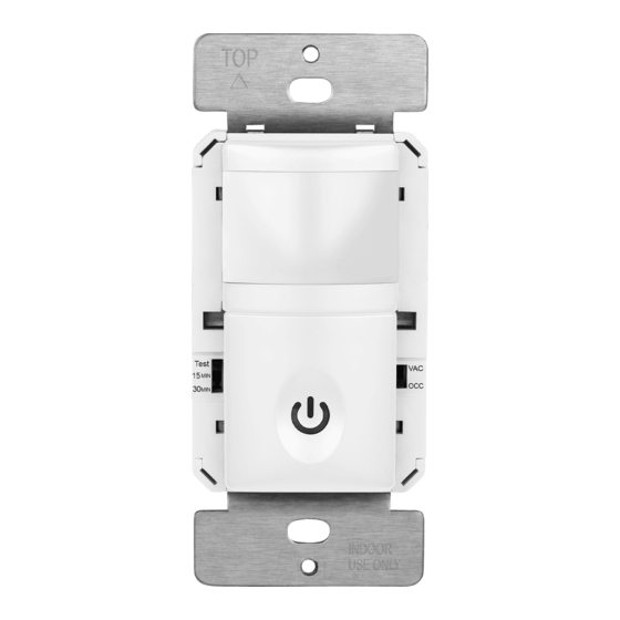
INSTALLATION INSTRUCTIONS
OCCUPANCY / VACANCY
SENSOR SWITCH
HMOS
SPECIFICATIONS
Voltage .......................................................................... 120VAC, 60Hz
Resistive ............................................................................................ 5A
Incandescent ........................................................................... 500W
Ballast........................................................................................500VA
Motor ......................................................................................... 1/8Hp
Time Delay.................................................... 15 Sec, 15 Mins, 30 Mins
Light Level...................................................................... Default setting
Operation Temperature.................................................... 32° F--131° F
DESCRIPTION
The passive infrared sensor detects the difference between heat emitted
from the human body in motion and the background space. The sensor
switch can turn a load on and hold it as long as the sensor detects
occupancy. After no motion is detected for the set time delay, the load turns
off automatically.
Coverage Area
The coverage range of the sensor switch is specified and illustrated
in Figure 1. Large object and some transparent barriers like glass
windows will block some degrees of the sensor's view and prevent detection,
causing the light turns even though someone is still in the detection area.
Top View
15'
7.5'
Best:180 sq.ft.
7.5'
Regular: 450 sq.ft.
15'
Maximum: 700 sq.ft.
5'
4'
15'
- 01-
HMOS
WARNING:
(2-IN-1)
INSTALLATION
1. Connect lead wires as shown in wiring diagram (see Figure 2): Black lead
to hot wire, red lead to load wire, white lead to neutral wire, green lead
to ground wire.
Wiring diagram
2. Device "TOP" upward.
3. Gently position wires in wall box, attach sensor switch to the box.
4. Restore power at circuit breaker or fuse, wait one minute.
5. Locate the toggle switch on both sides of the top cover to perform
test and adjustment.
Changing the color of your switch
The switch ships with top cover attached. It is convenient for
users to change the top cover. Please proceed as follows:
1.
Figure 1
30'
Push down top cover to release
Turn off the circuit breaker before installation.
Indoor use only.
Do not exceed electrical ratings.
Neutral
White
Top
Load
Hot
Black
Red
Ground
Neutral
Green
White
Figure 2
2.
Figure 3
Line up tabs and push up to attach
-02-
-02-
ADJUSTMENT
TOP
Test
Test
15 MIN
15 MIN
30 MIN
30 MIN
LED Indicator
USE ONLY
Load
Band switch prescription
Mode
Position
Vacancy Mode: Manual On only,
VAC
Upper side
Automatic Off after set time delay.
Occupancy Mode:
OCC
Automatic On, Automatic Off
Lower side
after set time delay.
Time delay setting
Default position
15 Seconds (Test mode)
Adjustable
15 Seconds
Ambient light(Default setting)
Notice:
If the ambient light level is too high, more than the default setting,
the load may not automatic turned ON, If turning ON is desired,
cover the sensor lens with one hand for 2 seconds, the light is
going to turn ON.
Mounting Yoke
Fresnel Lens
VAC
VAC
OCC
OCC
INDOOR
Control Top Cover
(ON/OFF Button)
Figure 4
Description
Function of ON/OFF button
Manually push
On/Off the load.
Manually push
On/Off the load.
15 Minutes
30 Minutes
-03-
Advertisement
Table of Contents

Subscribe to Our Youtube Channel
Related Manuals for Enerlites HMOS


Summary of Contents for Enerlites HMOS
- Page 1 INSTALLATION INSTRUCTIONS HMOS ADJUSTMENT WARNING: Turn off the circuit breaker before installation. Indoor use only. OCCUPANCY / VACANCY Mounting Yoke Do not exceed electrical ratings. (2-IN-1) Fresnel Lens SENSOR SWITCH INSTALLATION HMOS 1. Connect lead wires as shown in wiring diagram (see Figure 2): Black lead...
- Page 2 INSTALLATION INSTRUCTIONS This warranty service is available by returning the product with proof OPERATION TROUBLESHOOTING TROUBLESHOOTING` of purchase, purchase date and a description of the problem to the The sensor switch is programmed independently for either occupancy For proper operation, the sensor switch has to consume power from dealer from whom the unit was purchased.
Need help?
Do you have a question about the HMOS and is the answer not in the manual?
Questions and answers