Blue Sea Systems 1839 Instructions Manual
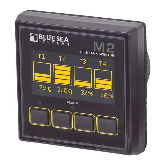
M2 oled tank monitor
Hide thumbs
Also See for 1839:
- Instructions manual (18 pages) ,
- Quick start installation manual (2 pages)
Advertisement
Quick Links
2
D
L
L
31
, VWDOODWLR &KHFNOLVW
&KHFN IRU FRPSRQHQWV LQFO GHG
5HDG :DUQLQ DQG &D WLRQV
5HDG
LFN6WDUW ,QVWDOODWLRQ * LGH IRU PR QWLQ LQVWU FWLRQV
5HDG 6 VWHP 2 HU LH
0R QWLQ &RQVLGHUDWLRQV
HWDLOHG :LULQ
DQG 6HQVLQ
HVFULSWLRQ
5HDG
LFN6WDUW ,QVWDOODWLRQ * LGH IRU LQVWDOODWLRQ QRWHV
ROOR ,QLWLDO 6 VWHP 6HW S LQVWU FWLRQV
• Con gure Displays
• Con gure Alarms
• Con gure Relays
LVSOD 6L H
PP
PP
3R HU 6 SSO
9
9 &
3R HU &RQV PSWLRQ
:
:
9DULDEOH LWK ROWD H GLVSOD LQWHQVLW DQG VOHHS PRGH
5H XODWRU
0RQLWRU IDFH LV ,3
SURWHFWHG D DLQVW SR HUI O DWHU MHWV
KHQ LQVWDOOHG DFFRUGLQ WR LQVWU FWLRQV
1839 Speci cations
7D NV
Senders
North American 240Ω–
Ω
URSHDQ
Ω–
Ω
%O H 6HD 6 VWHPV 8OWUDVRQLF
& VWRP
6HQGHU 5HVRO WLRQ
Custom Tank Shapes
Auto Calibration
:DU L
D G &DXWLR 6 PEROV
: 51,1
7KH
V PERO UHIHUV WR SRVVLEOH LQM U WR WKH VHU RU
signi cant damage to the meter if the user does not follow the procedures.
& 87,21 7KH
V PERO UHIHUV WR UHVWULFWLRQV DQG U OHV LWK UH DUG
WR SUH HQWLQ GDPD H WR WKH PHWHU
: 51,1
,I R DUH QRW NQR OHG HDEOH DER W HOHFWULFDO V VWHPV KD H DQ
HOHFWULFDO SURIHVVLRQDO LQVWDOO WKLV QLW 7KH GLD UDPV LQ WKHVH
LQVWU FWLRQV SHUWDLQ WR WKH LQVWDOODWLRQ RI 0
L LWDO 0HWHUV DQG QRW
WR WKH R HUDOO LULQ RI WKH HVVHO
,I DQ LQ HUWHU LV LQVWDOOHG RQ WKH HVVHO LWV SR HU OHDGV P VW EH
GLVFRQQHFWHG DW WKH EDWWHU EHIRUH WKH PHWHU LV LQVWDOOHG
• If an AC generator is installed on the vessel, it must be stopped
DQG UHQGHUHG LQRSHUDEOH EHIRUH WKH PHWHU LV LQVWDOOHG
• Verify that no other DC or AC sources are connected to the vessel's
LULQ EHIRUH LQVWDOOLQ WKH PHWHU
& 87,21
7KH EDFN RI WKH QLW LV QRW DWHUSURRI
R QRW LQVWDOO KHUH WKH EDFN
RI WKH PHWHU LV H SRVHG WR DWHU
&RPSR H WV , FOXGHG
M2 Head Unit
Surface Mount Bezel
Surface Mount Gasket
and Seal
Surface Mount Cover
Flat Mount Bezel
Flat Mount Clamp
Mounting Ring
Mounting Nut
Connector
Screwdriver
Retail Package Only
3D HO 0RX WL
.LW
31
VROG VHSDUDWHO
Header
#6-32 x 1/4"
Flat Head
Machine Screws
(4X)
Bezel
Panel
Mount
Frame
#6-32 x 3/8"
Carrier
Flat Head
Mount
Machine Screws
(4X)
Footer
#8 x 1/2"
Flat Head Sheet
Metal Screws
(4X)
, VWDOODWLR
1. Make all connections to the meter's terminal block before connecting the terminal block to the unit.
.HHS KDQGV D D IURP WKH WHUPLQDO EORFN KHQ DSSO LQ SR HU WR WKH PHWHU
2. As the nal DC connection, insert a fuse into the in-line fuse holder on the wire to the positive (+) battery terminal.
0RX WL
7HPSODWHV
Flat Mount
3.34" (84.8mm)
3.00" (76.2mm)
0RX WL
&R VLGHUDWLR V
M2 Digital Meters have three mounting methods: surface mount, at panel mount, and 360 panel mount. When surface mounted per instructions the
unit face is waterproof to IP66. Flat panel and 360 panel mounting systems are not waterproof. The unit should not be at panel or 360 panel mounted
LI VHG LQ DQ H SRVHG ORFDWLRQ
RU DOO PR QWLQ V WKH EDFN RI WKH QLW LV QRW DWHUSURRI DQG P VW EH NHSW GU
Surface Mount
Ø2.125"
(54mm)
3.40" (86.5mm)
Advertisement

Related Manuals for Blue Sea Systems 1839


Summary of Contents for Blue Sea Systems 1839
- Page 1 0RQLWRU IDFH LV ,3 SURWHFWHG D DLQVW SR HUI O DWHU MHWV KHQ LQVWDOOHG DFFRUGLQ WR LQVWU FWLRQV Surface Mount Cover Flat Mount Bezel Flat Mount Clamp 1839 Speci cations 3.34" (84.8mm) 7D NV Senders North American 240Ω– Ω 3.00" (76.2mm) URSHDQ 3.40"...
- Page 2 ,03257 17 The Sensing Description section of this manual gives important details to the location of sensors in the AC and DC electrical systems of the boat. Improper location and con guration of sensors can result in erroneous readings and possible damage to components. 3L RXW 7DEOH Mounting 1839 Connector Pin Assignment Table Ring and Nut 360 Panel 8 Pin Connector*...
- Page 3 HWDLOHG :LUL 0 5HOD &R HFWLR V M2 Meters contains an internal MOSFET relay that can drive external DC loads up to 0.5A. The input is protected with a thermally activated auto-reset- 7D N 0R LWRU ting fuse that will protect against shorts. In addition, an inline fuse rated at 5A should be used to protect against shorts. In typical applications, a power source is connected to the Relay+ pin and a load is connected to the Relay Out to Load connection.
- Page 4 HWWL 6WDUWHG ( WHU DO ODUP )OR G %HOO 7XUER The Relay+ terminal can support an external audible alarm. Such as the Floyd Bell Turbo Alarm (1070). ( DPSOH 6FUHH V )URP 31 7D N 0HWHU :KHQ DQ 0 0HWHU LV LQLWLDOO SR HUHG S LW LOO GLVSOD WKH %O H 6HD 6 VWHPV /R R LWV VHULDO Q PEHU DQG LWV 6RIW DUH UH LVLRQ After a couple of seconds, the unit will display a high-level System Summary screen.
- Page 5 Con guring the Meter &OHDUL ODUPV When an alarm occurs, the buzzer will sound, the red ALARM LED will light, and the screen will display which alarm was triggered, the Alarm set point Meter settings can be con gured from the Setup menu. This menu can be accessed by pressing the 0H X E WWRQ DQG WKHQ VFUROOLQ WR DQG VHOHFWLQ DQG WKH F UUHQW DO H 3UHVVLQ DQ E WWRQ VLOHQFHV WKH E HU DQG DQRWKHU E WWRQ SUHVV UHW UQV WR WKH SUH LR V GLVSOD 6HW S 3UHVV WKH 83 ↑...
- Page 6 6HWWL , SXW 7KUHVKROGV Clearing Relay Noti cation Settings for each channel’s high and low tank thresholds are provided. The connected relay’s normal operating state will toggle (change state) if these If the Noti cation option is set to ON then any time the relay is opened (Normally Off) or closed (Normally On). A message will be displayed on the main WKUHVKROGV DUH PHW RU ERWK KL K DQG OR WKUHVKROGV WKH DFWL DWLRQ DQG GHDFWL DWLRQ OH HOV DUH GLIIHUHQW WR SUH HQW WKH UHOD IURP UDSLGO WR screen.
- Page 7 &KD 6 VWHP /DEHOV 7D N HSWK 2 O XVHG 6H GHUV 7KH 0 DOOR V WKH VHU WR FKDQ H WKH ODEHOV WKDW DUH GLVSOD HG DER H HDFK FKDQQHO DFK FKDQQHO FDQ KD H D PD LP P RI FKDUDFWHUV KR H HU LQ 7KLV VHWWLQ LQGLFDWHV WKH GHSWK RI WKH WDQN LQ LQFKHV 7KLV VHWWLQ LV QRW DIIHFWHG E V LWFKLQ WKH QLWV LQ 6HWXS ! LVSOD !8 LWV the summary screens only the rst 11 or 12 characters of the channel label are displayed.
- Page 8 XWR &DOLEUDWH 6RIW DUH 8S UDGH The meter rmware can be updated in one of two ways. The rst option is to use the Software Upgrade option in the Setup menu. The second option is The Auto-Calibrate function requires the tank to be lled at a constant rate and for the sensor reading be initially less than 15%. For grey, waste, and WR IRUFH WKH PHWHU LQWR S UDGH PRGH RQ VWDUW S water tanks a hose can be used to provide a constant ow.
- Page 9 425 Sequoia Drive Bellingham, WA 98226 USA p 800.222.7617 USA and Canada Customer Service f 360.734.4195 FRQG FWRU EO HVHD FRP EO HVHD FRP...
Need help?
Do you have a question about the 1839 and is the answer not in the manual?
Questions and answers