Table of Contents
Advertisement
Quick Links
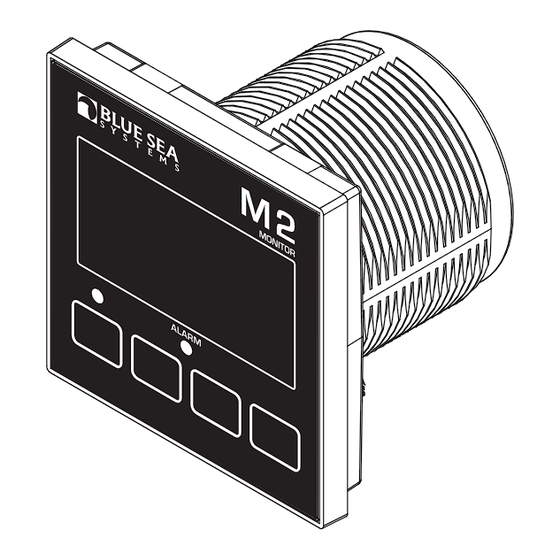
M2 Vessel Systems Monitor (M2-VSM)
PN 1850
Installation Checklist
Check for components included
Read Warning and Cautions
Read QuickStart Installation Guide for mounting instructions
Read System Overview, Mounting Considerations, Detailed Wiring,
and Sensing Description
Read QuickStart Installation Guide for installation notes
Follow Initial System Setup instructions
Configure Displays
Configure Alarms
Specifications
Display Size 55mm x 28mm
Power Supply
Power Consumption
NMEA 2000 Load Equivalency
DC Voltage
Voltages
Range
Resolution
Voltage Accuracy
DC Current
Shunt Included
Range
Current Accuracy
Resolution (100 to 500)
Resolution (0.0 to 99.9)
Alarm Activation
AC Voltage
Range
Resolution
AC Current
Range
Resolution (100 to 150)
Resolution (0.0 to 99.9)
Current Transformer
Alarm Activation
Frequency
Range
Resolution
Power
Range
Resolution (0W–9990W)
Resolution (10kW–45kW)
†
Tanks
Alarm
Senders
Sender Resolution
Custom Tank Shapes
Alarm Notification
Regulatory
Monitor face is IP66 – protected against powerful water jets
when installed according to instructions
* Variable with voltage, display intensity, and sleep mode
** Will achieve 300A with an optional current transformer PN 1829
† Compatible with bilge monitors with external float switches or with automatic
bilge switches that indicate on status via a 12V output.
7V–70V DC
0.3W–1.0W*
1
12V, 24V, 36V, 48V
7V–70V DC
0.01V DC
+/- 1%
1 × PN 8255 (500A / 50mV)
−500A to 500A
+/- 1%
1A
0.1A
High and Low Voltage,
High Current, and Low Battery
50V–250V AC (RMS)
1V AC
0A to 150A (300A optional) **
1A
0.1A
1 × PN 8256 (150A / 50mA)
High and Low Voltage, Current,
and Frequency
40Hz–90Hz
1Hz
0W–45kW
10W
0.1kW
High/Low Levels
North American 240Ω–33Ω
European 10Ω–180Ω
Blue Sea Systems Ultrasonic
Custom
1%
Auto Calibration
Run time per hour
Cycles per 24-hour
Cycle Counter
Components Included
M2 Head Unit
Surface Mount Bezel
and Seal
Surface Mount Cover
Flat Mount Bezel
Mounting Ring
Mounting Nut
Connectors
Screwdriver
Retail Package Only
360 Panel Mounting Kit PN 1525
Header
Bezel
Mount
Carrier
Mount
Footer
Instructions
Surface Mount Gasket
Flat Mount Clamp
PN 8255 Shunt (1X)
AC Current Transformer
8256
(sold separately)
#6-32 x 1/4"
Flat Head
Machine Screws
(4X)
Panel
Frame
#6-32 x 3/8"
Flat Head
Machine Screws
(4X)
1
Advertisement
Table of Contents

Subscribe to Our Youtube Channel
Related Manuals for Blue Sea Systems M2 Vessel Systems Monitor


Summary of Contents for Blue Sea Systems M2 Vessel Systems Monitor
-
Page 1: Specifications
Instructions M2 Vessel Systems Monitor (M2-VSM) PN 1850 Components Included Installation Checklist Check for components included Read Warning and Cautions Read QuickStart Installation Guide for mounting instructions Read System Overview, Mounting Considerations, Detailed Wiring, and Sensing Description Read QuickStart Installation Guide for installation notes... -
Page 2: Resource Information
Resource Information State-of-Charge (SOC) http://bluesea.com/viewresource/1324 AC Current Measurement http://bluesea.com/viewresource/86 Warning and Caution Symbols WARNING: The symbol refers to possible injury to the user or significant damage to the meter if the user does not follow the procedures. CAUTION: The symbol refers to restrictions and rules with regard to preventing damage to the meter. WARNING • Verify that all AC sources are disconnected before connecting or disconnecting the current transformer. Failure to do so will generate lethal voltages on the current transformer. • If you are not knowledgeable about electrical systems, have an electrical professional install this unit. The diagrams in these instructions pertain to the installation of M2 Digital Meters and not to the overall wiring of the vessel. • If an inverter is installed on the vessel, its power leads must be disconnected at the battery before the meter is installed. • If an AC generator is installed on the vessel, it must be stopped and rendered inoperable before the meter is installed. • Verify that no other DC or AC sources are connected to the vessel’s wiring before installing the meter. CAUTION • The back of the unit is not waterproof. Do not install where the back of the meter is exposed to water. -
Page 3: Mounting Considerations
Mounting Considerations M2 Digital Meters have three mounting methods: Surface mount, Flat panel mount, and 360 panel mount. When surface mounted per instructions the unit face is waterproof to IP66. Flat panel and 360 mounting systems are not waterproof. The unit should not be flat panel or 360 mounted if used in an exposed location. For all mountings, the back of the unit is not waterproof and must be kept dry. Flat Mount 360 Panel Mount PN 1525 STEP 1 Use 1/4" Mounting Screws Mounting Ring and Nut 360 Panel Mount Carrier Clamp Panel Frame Flat Head Mount Mounting STEP 2 Unit Bezel Substrate Snap header and footer Header into mounting... - Page 4 Functions DC Functions • Monitor the voltages of up to two battery banks and current draw on one battery bank. • Provides battery State-of-Charge (SoC), capacity, amp hours (Ah) remaining, and charge cycles. AC Functions • Monitors the voltages, current draws, frequency, and power of one AC source. Tank/Bilge Functions • Monitor up to two tanks or bilges • Provides High/Low level alarms for each tank • Keeps track of total bilge run time in the last hour • Keeps track of the total number of bilge cycles in the last 24 hours. • Keeps track of the average number of 24-hr bilge cycles in the last week • Keeps track of the total number of bilge cycles Connections IMPORTANT! The Sensing Description section of this manual gives important details to the location of sensors in the AC and DC electrical systems of the boat. Improper location and configuration of sensors can result in erroneous readings and possible damage to components. Pin-out Table Detailed Wiring Connector Pin Assignment Table Function 2 Pin Connector* 3.5mm Fuse Shunt Battery 1-...
- Page 5 Install a sender for each gauge if you wish to read a tank level from more than one location. The Blue Sea Systems ultrasonic sender requires an external power source. When power to the sender is lost, the M2 VSM will read the tank as full, and may trigger the tank’s high level alarm. For each tank the sender must be specified, and the shape of the tank set as rectangular or auto-calibrated before accurate readings are displayed. Blue Sea Systems Ultrasonic Sender 1810, 1811 Resistive 2 Wire Sender OPTIONAL OPTIONAL SECOND TANK...
-
Page 6: Getting Started
Getting Started Example Screens When an M2 Meter is initially powered up, it will display the Blue Sea Systems Logo and the serial number of the meter. After a couple of seconds, the unit will display a high-level System Summary screen. With AC Without AC Pressing any button will display a temporary pop-up menu. Select an option by pressing the button beneath it. The pop-up menu will disappear after the first button is pressed. The menu system is a two dimensional matrix. Pressing the UP or DOWN arrow buttons will transition the display between the System Summary, screen which displays summary information for each of the “voltage” , “current”, or “sensor” channels. Press the Next button to display more detailed information about an input channel, or to show a single parameter such as “voltage” in the display (see example below). This Screen OR This Screen... -
Page 7: Main Screens
Main Screens Summary Screen The main summary screen display shows the state of the M2-VSM at a glance. On the left it displays the voltage, current, and state-of-charge for Battery 1, and the voltage for Battery 2. The arrow to the left of the battery display indicates if that battery is being charged or discharged If AC is present, the display will display voltage and current as well as a graphical representation of the tank level, and/or the bilge runtime over the last hour. In the above examples, the bilge ran 15 minutes over the last hour. If AC is not present, the AC display shuts off. Depending on the tank setup, the tank levels are now displayed in percent or volume. The Bilge has two additional fields. The top number is the total number of cycles in the last 24-hours. The bottom number displays the number of cycles over the last seven days divided by 7. This is the daily average. Compare this count with the 24-hour count to see if the bilge is running more or less often. For example, in B2 the 24-hour count is 42, while the Avg is 15. This tells you that the bilge is running more often than normal. SOC Summary Screens The 1850 provides summary information about the state-of-charge (SOC) of the main battery (DC1). • Time to Alarm - If an SOC alarm is set, this displays the estimated time before the alarm goes off (exclusive of delays). If no alarm is set, this is the estimated time until the battery is completely empty. • Ah Remain - Estimated remaining capacity of the battery. • Ah Used - This is the actual Ah removed from the battery since the last full charge including all discharge and charge cycles. Note that Ah Used and Ah Remain will add up to be less than the capacity of the battery since the efficiency of removing energy from a battery varies depending on the rate of discharge. •... -
Page 8: Setup Menu
Configuration Setup Menu Meter settings can be configured from the Setup menu. This menu can be accessed by pressing the Menu button and then scrolling to and selecting Setup. Press the UP and DOWN arrow buttons to move the cursor. The different setup options are described below. NMEA Setup CZone Configuration To use CZone, first configure the DIPSWITCH setting to match the setting that was defined in the CZone configuration tool. Then turn the CZone menu to ON. The meter will reboot and pull the configuration information from the network. Note that the NMEA cable must be connected to a live CZone network with proper configuration data.The CZone configuration file will automatically populate most configuration data for the M2 VSM including: NMEA 2000 instances, battery voltage, battery type, battery capacity, full charge volts, full charge amps, and tank/bilge configuration. NMEA 2000 Configuration For non-CZone systems, the user will have to enter NMEA 2000 instance information for DC1, DC2, AC1, and the Tanks (if used). The user should configure the instance information before connecting to the N2K network to prevent conflicts. Alarm Setup The meter supports two types of alarms, local alarms that are only displayed on the meter and CZone alarms that are displayed on CZone displays and can be used to configure CZone switching. CZone alarms are configured in the CZone configuration tool while local alarms are configured on the meter. - Page 9 Silent Alarm This turns off the alarm buzzer. Alarms will only show on the main screen. Voltage Alarm Voltage alarms can be set to detect high (Hi) or low (Lo) voltage conditions. Current Alarm The current alarm can be set to detect over current conditions. State-of-Charge (SoC) Alarm The State-of-Charge alarm can be set to detect low State-of-Charge conditions. Tank Alarm Alarms can be set to detect tank levels. Bilge Alarm Bilge alarms can be set to detect if the run-time exceeds a certain value in at 60-minute period (Bilge Time Hi) or if the number of cycles in a 24-hour period exceeds a threshold (Bilge Cycle Hi). Alarm Delay An alarm delay can be specified so that alarms don’t immediately trigger. This can be useful when monitoring a starting battery, so that the alarm doesn’t trigger every time an engine is started. The hold off timer operates as a count-up/count-down timer. When the input exceeds the alarm value, the timer will start counting up until it reaches the delay time. When it reaches the delay timer, an alarm will sound. If the alarm condition goes away before the delay timer has been met, the timer will count down until the timer is zero again. For example; if the Alarm Delay is set for 5 minutes and an alarm condition is active for 4 minutes then inactive for 1 minute, if the alarm condition is active again, the alarm will sound in 2 minutes (5 minutes - 4 minutes + 1 minute). Note that there is only one delay per channel. Clearing Alarms When an alarm occurs, the buzzer will sound, the red ALARM LED will light. The screen will display which alarm was triggered, the alarm set point and the current value. Pressing any button silences the buzzer and another button press returns to the previous display.
-
Page 10: Display Setup
Display Setup The meter display settings can be accessed from the Display Setup menu. From the setup screen, scroll to Display Setup and press the Select button. The different display settings are described below. To change a setting, press Enter and press the LEFT or RIGHT arrow buttons to view the available setting options. Press Enter to save the setting. Press Cancel to cancel a change. None of these settings are modified by CZone. Brightness This setting is for adjusting the brightness of the display. The value is a percentage where 0 % is dimmest and 100 % is brightest. Sleep Timer Following a certain period of inactivity, the meter will enter a sleep mode and will turn off the display. Any button may be pressed to exit the sleep mode and restore the display. The Sleep Timer sets the number of minutes from 0 to 600 before entering sleep mode. This feature will be disabled by chang- ing the setting to OFF. Dim Timer In addition to sleep mode, the meter can also dim its display after a period of inactivity. The duration of delay in minutes from 0 to 600 can be adjusted with this setting. This feature will be disabled by changing the setting to OFF. By continuously pressing the LEFT... -
Page 11: Battery Voltage
DC1 Setup The meter provides setup settings for each battery. To access these settings, first go to the Setup menu. Scroll to the desired battery label followed by Setup (such as DC1 Setup), then press Select. NOTE: Some settings may not be available for all batteries. The battery setup settings are described below. To make a change, scroll to setting and press Enter. Press the LEFT or RIGHT arrow buttons to view the available setting options. Press Enter to save the setting. Press Cancel to cancel a change. Enable To display the battery and its measurements, change this setting to ON. If enable is OFF, the battery along with its measured values will not be displayed. However, any associated alarm settings are still active. To de-activate the alarm, disable them in the Alarm Setup menu. Set State-of-Charge (SoC) to FULL When this option is selected, the meter will consider the battery’s present State-of-Charge to be FULL. To do this, scroll to Ok and press Select. The screen will then return to the meter summary display. - Page 12 Full Chrg Amps In addition to Voltage, the user can set the Charging Current at which the battery is considered fully charged. The value is a percentage between 0.0 % and 10.0 % of the battery’s set Amp-hour capacity. This value should be set to 0.2% higher than the End of Absorption Amps. That is the current where the battery charger switches from Absorb to Float stage. Values are typically 2% for AGM and 3% for Lead Acid. As a battery ages, this percentage may need to be increased. This is automatically set by CZone. Charge Eff. This setting is for indicating the battery’s percent charge efficiency. The value may be set between 0% and 100%. The user can adjust the charge efficiency up or down depending on the age and/or type of battery that they are using. AGM Batteries tend to be much more efficient than Lead Acid Batteries. If the M2 meter indicates 100% before the charger is done with its bulk charge then the efficiency is likely too high. Try decreasing it a couple percent. If the M2 meter never indicates full charge then efficiency is likely too low. Try increasing it a couple percent. This is automatically set by CZone. The charge efficiency can be calculated as follows: 1. Set the Charge Eff. Value to 100%. 2. Discharge the battery somewhere between 25% to 50%. 3. Check the SoC summary screen and note the Ah Used value (it will be a negative number). This is Discharge Amps. 4. Charge the battery using a 3-stage charger. 5. When the charger goes from Absorption to Bulk, the battery is considered fully charged. 6. Check the SoC screen again and note the Ah Used (it will be a positive number). This is Charge Amps. 7. The new Charge Efficiency value is calculated by Discharge Amps/Charge Amps.
- Page 13 DC2 Setup Enable Turn the channel on or off. If Enable is set to OFF then the channel will not be displayed in the main menus. The alarm functions for that channel will not be disabled. To disable the alarm for a channel, set the alarm for each channel to OFF. AC1 Setup Enable To display the channel and its measurements, change this setting to ON. If enable is OFF, the channel along with its measured values will not be displayed. However, any associated alarm settings are still active. To de-activate the alarm, disable them in the Alarm Setup menu. Toggle A/V Switch the Current and Voltage display on the channel’s Summary Screen. If this option is set to OFF then Voltage will be displayed in the center field. If the option is set to ON Current will be displayed in the center field. Example: Toggle A/V Set to OFF Full Scale Amps The M2 is shipped with a 150A AC/50mA AC current transformer (the ratio is 3000:1). The full scale output is based on transformers with a maximum output value of 50mA AC. A different value transformer can be calculated with the following formula: Full Scale Amps = New Ratio / 20. For example to replace the standard transformer with a 100A/20mA transformer (Note: 20mA = 0.02A): (100A/ 0.02) /20 = 250A. Tank / Bilge Setup The meter has two inputs that can be configured as either a bilge or tank. To access these settings, first go to the Setup menu.
- Page 14 Resistance Lo/Resistance Hi The tank meter operates by reading the resistance of the tank sender. The resistance value (in ohms) can be entered here for an empty tank (Resistance Lo) and for a full tank (Resistance Hi). Changing either of these values when the Sender Type is set to either 1810 or 1811 will give unpredictable results when an Ultrasonic Tank Sender is used. Tank Depth (Only used with 1810 and 1811 Senders) This setting indicates the depth of the tank in inches. This setting is not affected by switching the units in Setup->Display->Units. Also note that this setting is only used for ultrasonic senders. Tank Shape • Rect – Standard Rectangular Tank • Tri – Triangular Shaped Tank. Good for tanks in Bilges.
- Page 15 Using Auto-Calibrate The Auto-Calibrate function requires the tank to be filled at a constant rate and for the sensor reading be initially less than 15%. For grey, waste, and water tanks a hose can be used to provide a constant flow. Diesel and gas tanks can be more difficult because foaming may cause the user to slow down filling once the tank is almost full. If foaming is a problem then use the manual method described above. 1. Select Setup->Tank(1-4)->Auto Calibrate->Ok 2. If the sensor reads more than 15% an error message will be displayed along with the sensor reading. At this point the tank can be emptied or the back button can be pressed to exit the auto calibrate procedure. 3. If the sensor is less than 15% then an option to start the calibration process is given. 4. Press the Start button and start filling the tank at a constant rate. 5. The timer will start counting as the tank fills. In addition the sender will indicate that the tank is getting filled. When the tank reaches 100% the timer will automatically stop. Press the Finish button to accept the calibration values or the Cancel to abandon the changes. If the tank is full before the sender reaches 100% then press Finish. 6. After the Finish button is pressed the M2 will populate Sensor 20% - Sensor 100% with the proper calibration values. Scroll down to inspect the values. Version Info The Version Info option in the Setup menu displays the product name, serial number, and software version. This information will be displayed on a screen after scrolling to Version Info and pressing Select. Pressing any button will return to the Setup menu. Factory Reset The Factory Reset option in the Setup menu allows the user to restore the meter’s factory default settings. First scroll to Factory Reset and press Select. Text will appear asking to confirm or cancel the reset request. Press Yes to confirm or No to cancel the reset.
- Page 16 PGN’s Used with 1850 PGN Number Description Fields 127506 DC Detailed Status State-of-Charge (Time remaining will follow) 127508 Battery Status Battery Voltage, Battery Current 127503 AC Input Status Voltage, Current, Real Power 127504 AC Output Status Voltage, Current, Real Power 127505 Fuid Level Type, Level, Capacity PGN Number Description 59392 ISO Acknowledgement 59904 ISO Request 160160 ISO Transport Protocol, Data Transfer 60416 ISO Transport Protocol, Connection Management 60928...
-
Page 17: Software Upgrade
Software Upgrade New Method 1. This upgrade method only works with Windows 7 PCs and above, and MAC OSX 10.8 and above. 2. Download the new firmware from http://www.bluesea.com/m2firmware. 3. Extract the firmware.bin file from zip file. 4. Remove all connections from the meter. 5. Plug a USB micro cable into the back of the meter. 6. While holding the 2nd button from the left connect the USB cable to a PC or a MAC While holding the 2nd button from the left connect the USB cable to a PC or a MAC 7. The computer will create a new drive on the computer. Note: If the PC doesn’t recognize the M2-VSM, then try using a different cable. a. On a PC, the new drive will have be labeled as CRP_DISABLD (D:) where “D:” is the drive letter and may be a different letter. - Page 18 8. Delete the firmware.bin file from the M2-VSM folder. a. On a PC, select the file with your mouse and press the delete key. b. On a Mac, select the file with your mouse and move to trash. 9. Copy the new firmware.bin file to the M2-VSM folder. 10. Unplug the USB cable from the computer. 11. You can plug the usb cable back into the computer to verify the new firmware. The M2-VSM should power up and you can navigate to Setup->Version Info to verify the new SW Revision. 4600 Ryzex Way Bellingham, WA 98226 USA p 360.738.8230 f 360.734.4195 conductor@bluesea.com bluesea.com 980033760 Rev. 001...
Need help?
Do you have a question about the M2 Vessel Systems Monitor and is the answer not in the manual?
Questions and answers