
Related Manuals for Guntermann & Drunck ControlCenter-Digital-160


Summary of Contents for Guntermann & Drunck ControlCenter-Digital-160
- Page 1 Guntermann & Drunck GmbH www.gdsys.de ControlCenter-Digital-160 Installation und Bedienung Installation and Operation A9100230-1.51...
- Page 2 © Guntermann & Drunck GmbH 2021. Alle Rechte vorbehalten. Version 1.51 – 28.01.2021 Firmware: 2.3.000 Guntermann & Drunck GmbH Obere Leimbach 9 57074 Siegen Germany Telefon +49 (0) 271 23872-0 Telefax +49 (0) 271 23872-120 www.gdsys.de sales@gdsys.de i · G&D ControlCenter-Digital-160...
- Page 3 Operation of this equipment in a residential area is likely to cause harmful inter- ference in which case the user will be required to correct the interference at his own expense. G&D ControlCenter-Digital-160 · ii...
-
Page 4: Table Of Contents
Konfiguration der Netzwerkschnittstellen ............17 Konfiguration der »globalen« Netzwerkeinstellungen ........18 Verwendung des Reset-Tasters ............... 20 Wiederherstellung der Standardeinstellungen ........... 20 Temporäre Deaktivierung der Netzfilterregeln ..........21 Erweiterung der schaltbaren Signale ............... 22 Statusanzeigen ....................23 Technische Daten ................... 26 iii · G&D ControlCenter-Digital-160... -
Page 5: Sicherheitshinweise
Um das Risiko eines Stromschlags zu vermeiden, sollten Sie das Gerät nicht öffnen oder Abdeckungen entfernen. Im Servicefall wenden Sie sich bitte an unsere Techniker. Geerdete Spannungsquelle verwenden Betreiben Sie dieses Gerät nur an einer geerdeten Spannungsquelle. G&D ControlCenter-Digital-160 · 1... - Page 6 Gerät einige Zeit abkühlen, bevor weitere Arbeiten durchgeführt werden. Betreiben Sie das Gerät ausschließlich im vorgesehenen Einsatzbereich Die Geräte sind für eine Verwendung im Innenbereich ausgelegt. Vermeiden Sie extreme Kälte, Hitze oder Feuchtigkeit. Die Geräte sind nicht für die Verwendung in gefährlichen Umgebungen zugelassen. 2 · G&D ControlCenter-Digital-160...
- Page 7 Mettre au rebut les batteries usagées conformêment aux instructions du fabricant et de manière écologique. Les batteries usagées ne doivent pas être jetées dans les ordures ménagères. Respectez les prescriptions valables pour l'élimination des produits électroniques. G&D ControlCenter-Digital-160 · 3...
- Page 8 Sicherheitshinweise Besondere Hinweise zum Umgang mit Laser-Technologie Die Fiber-Varianten der ControlCenter-Digital-160-Serie verwenden Baugruppen mit Laser-Technologie, die der Laser-Klasse 1 oder besser entsprechen. Sie erfüllen dabei die Richtlinien gemäß EN 60825-1:2014 sowie U.S. CFR 1040.10 1040.11 Unsichtbare Laserstrahlung, LASER KLASSE 1...
-
Page 9: Der Matrixswitch "Controlcenter-Digital
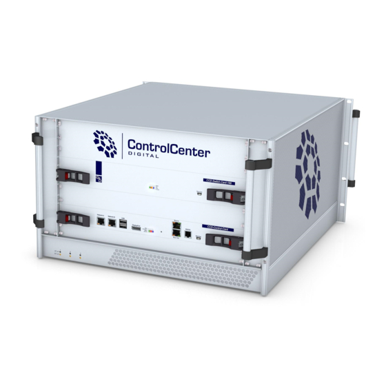
Der Matrixswitch »ControlCenter-Digital« Der Matrixswitch »ControlCenter-Digital« Der Matrixswitch ControlCenter-Digital-160 ist die zentrale Komponente eines KVM- Matrixsystems. Service Status Fail Ident. Function Bus IN Network A Network B DisplayPort RS232 Service Status Fail Ctrl Ident. Fail Comm. Bus OUT AC ok... -
Page 10: Lieferumfang
Lieferumfang Lieferumfang 1 × Matrixswitch ControlCenter-Digital-160 3 × Stromversorgungskabel (PowerCable-2 Standard) 2 × Montageschienen inkl. Befestigungsmaterial 1 × Blindblende für IO-Steckplatz (CCD-IO-16-Card-Cover) 1 × Blindblende für Stromversorgungs-Schacht (CCD-Power-Module-Cover) 1 × Service-Kabel (USB-Service-2) 1 × Handbuch »Installationsanleitung«... -
Page 11: Modularer Aufbau Des Matrixswitches
Modularer Aufbau des Matrixswitches Modularer Aufbau des Matrixswitches Dank des modularen Aufbaus des Matrixswitches ControlCenter-Digital-160 können Sie den Matrixswitch durch den Einbau weiterer IO-Karten erweitern oder System- komponenten ersetzen. Übersicht der Komponenten des Matrixswitches Auf der Frontseite sind die Switch-Karte CCD-Switch-Card-160 und die Controller- Karte CCD-Control-Card platziert. - Page 12 mäßige Staubbelastung: leichte Staubbelastung: 6 Monate Prüfen Sie regelmäßig den Zustand der Filter. Reinigen Sie leicht verschmutzte Filter durch Ausklopfen und/oder leichte Luftstöße mit Druckluft. Wechseln Sie den Filter spätestens nach einem Zeitraum von 6 Monaten. 8 · G&D ControlCenter-Digital-160...
-
Page 13: Komponenten Ein- Oder Ausbauen
Beachten Sie diesbezüglich folgende Sicherheitshinweise: Blickkontakt mit dem unsichtbaren Laserstrahl vermeiden auf Seite 4 Optische Anschlüsse stets verbinden oder mit Schutzkappen abdecken auf Seite 4 Ausschließlich von G&D zertifizierte Übertragungsmodule verwenden auf Seite 4 G&D ControlCenter-Digital-160 · 9... - Page 14 4. Stellen Sie sicher, dass die Hebel Kontakt zum Gehäuse haben und auf der Höhe der vorgesehenen Löcher der Lochschiene platziert sind. 5. Drücken Sie die Hebel ohne große Kraftanwendung nach innen, um die Karte am Gehäuse zu fixieren. 10 · G&D ControlCenter-Digital-160...
-
Page 15: Lüfter-Boards Ein- Oder Ausbauen
So bauen Sie die Controller-Karte aus: 1. Schalten Sie die Schalter der Spannungsversorgungsmodule Power 1 Power 2 Power 3 aus. 2. Drücken Sie die roten Schieber der Karte gleichzeitig in Pfeilrichtung, um die Hebel zu entriegeln. G&D ControlCenter-Digital-160 · 11... -
Page 16: Switch-Karte Ein- Oder Ausbauen
Schacht. 4. Stellen Sie sicher, dass die Hebel Kontakt zum Gehäuse haben und auf der Höhe der vorgesehenen Löcher platziert sind. 5. Drücken Sie die Hebel nach innen, um die Karte im Gehäuse zu fixieren. 12 · G&D ControlCenter-Digital-160... -
Page 17: Installation
Matrixswitches an ein bzw. zwei lokale Netzwerke. Hinweise zu den Kabelwegen Der modulare Aufbau des Matrixswitches ControlCenter-Digital-160 ermöglicht die einfache Erweiterung, den Austausch und die Wartung der Komponenten. Bedenken Sie beim Verkabeln der Komponenten, dass die Lüfter-Boards in regelmäßi- gen Abständen (s. -
Page 18: Installation Und Anschluss Der Arbeitsplatzmodule
Optische Anschlüsse stets verbinden oder mit Schutzkappen abdecken auf Seite 4 Ausschließlich von G&D zertifizierte Übertragungsmodule verwenden auf Seite 4 HINWEIS: Die Installation der Module wird im separaten Handbuch Target- und Arbeitsplatzmodule detailliert beschrieben. 14 · G&D ControlCenter-Digital-160... -
Page 19: Stromversorgung
Das andere Ende des Kabels ist mit einer Netzwerkschnittstelle eines lokalen Netz- werks zu verbinden. Stecken Sie optional ein als Zubehör erhältliches Twisted-Pair-Kabel der Network B: Kategorie 5e (oder höher) ein. Das andere Ende des Kabels ist mit einer Netzwerkschnittstelle eines lokalen Netz- werks zu verbinden. G&D ControlCenter-Digital-160 · 15... -
Page 20: Empfehlungen Zum Twisted-Pair-Kabel
80 Meter: Dätwyler uninet® 7702 flex Patchkabel bis 100 Meter: Dätwyler uninet® 5502 AWG24 S-STP Installationskabel mit Steckern bis 140 Meter: Kerpen MegaLine® G12-150 S/F AWG22 Installationskabel mit Buchsen Dätwyler uninet® 7702 AWG 22 Installationskabel mit Buchsen 16 · G&D ControlCenter-Digital-160... -
Page 21: Erstkonfiguration Der Netzwerkeinstellungen
, um die Anmeldung durchzuführen und das On-Screen-Display zu öffnen. 3. Betätigen Sie die -Taste zum Aufruf des Configuration -Menüs. 4. Wählen Sie die Zeile und betätigen Sie die Network Eingabetaste 5. Wählen Sie die Zeile und betätigen Sie die Interfaces Eingabetaste G&D ControlCenter-Digital-160 · 17... -
Page 22: Konfiguration Der "Globalen" Netzwerkeinstellungen
Strg+Num das On-Screen-Display zu starten. 2. Betätigen Sie die -Taste zum Aufruf des Configuration-Menüs. 3. Wählen Sie die Zeile Network und betätigen Sie die Eingabetaste 4. Wählen Sie die Zeile Interfaces und betätigen Sie die Eingabetaste 18 · G&D ControlCenter-Digital-160... - Page 23 Geben Sie die IP-Adresse des Gateways an. DNS Server 1: Geben Sie die IP-Adresse des DNS-Servers an. DNS Server 2: Geben Sie optional die IP-Adresse eines weiteren DNS-Servers an. 6. Betätigen Sie die -Taste zur Speicherung der durchgeführten Änderungen. G&D ControlCenter-Digital-160 · 19...
-
Page 24: Verwendung Des Reset-Tasters
3. Halten Sie den Taster weiterhin gedrückt und schalten Sie mindestens ein Spannungsversorgungsmodul des Geräts ein. 4. Sobald die grüne Status-LED leuchtet, lassen Sie die Taste los. HINWEIS: Die Wiederherstellung der Standardeinstellungen ist alternativ auch über die Webapplikation Config Panel möglich. 20 · G&D ControlCenter-Digital-160... -
Page 25: Temporäre Deaktivierung Der Netzfilterregeln
3. Bearbeiten Sie die im Gerät gespeicherten Netzfilterregeln mit der Webapplika- tion Config Panel und speichern Sie die Regeln anschließend ab. WICHTIG: Wird innerhalb von 15 Minuten keine neue Netzfilterkonfiguration erstellt, werden die ursprünglichen Einstellungen wieder aktiviert. G&D ControlCenter-Digital-160 · 21... -
Page 26: Erweiterung Der Schaltbaren Signale
Durch die Zuordnung mehrerer Kanäle zu einem Arbeitsplatz oder einem Rechner erstellen Sie eine sogenannte Kanal-Gruppierung. HINWEIS: Arbeitsplatz- bzw. Rechnermodule, die Sie als Zusatzkanal einer Kanal-Gruppierung zugeordnet haben, werden im OSD nicht aufgeführt. Ausführliche Informationen zur Kanal-Gruppierung finden Sie im Handbuch der Webapplikation. 22 · G&D ControlCenter-Digital-160... -
Page 27: Statusanzeigen
LED zur Identifizierung des Gerätes in der Webapplikation aktiviert. Network A gelb flackert Netzwerkaktivität findet statt. keine Netzwerkaktivität grün Netzwerkverbindung hergestellt. Keine Netzwerkverbindung Network B gelb flackert Netzwerkaktivität findet statt. keine Netzwerkaktivität grün Netzwerkverbindung hergestellt. Keine Netzwerkverbindung G&D ControlCenter-Digital-160 · 23... - Page 28 In der Webapplikation wird dieser Modus als DOWN- Modus bezeichnet. flackert Tastatur- und Mauseingaben werden vom aufgeschalte- ten Arbeitsplatzmodul übertragen. Der Rhythmus des Flackerns wird durch die Eingaben des Anwenders bestimmt. Es konnte keine Verbindung zum Arbeitsplatz- bzw. Targetmodul hergestellt werden. 24 · G&D ControlCenter-Digital-160...
- Page 29 Das Spannungsersorgungsmodul wird mit der erforderlichen Eingangs- spannung versorgt. grün Der Matrixswitch wird mit der erforderlichen Spannung durch das Span- nungsversorgungsmodul versorgt. Die Ausgangsspannung ist fehlerhaft. Der Matrixswitch wird nicht mit der Spannung dieses Spannungsversor- gungsmoduls versorgt. G&D ControlCenter-Digital-160 · 25...
-
Page 30: Technische Daten
Einsatzumgebung Temperatur: +5 bis +40 °C Luftfeuchte: 20 % bis 80 %, nicht kondensierend Lagerumgebung Temperatur: -20 °C bis +60 °C Luftfeuchte: 15 % bis 85 %, nicht kondensierend Konformität CE, EAC, FCC Klasse A, RoHs 26 · G&D ControlCenter-Digital-160... - Page 32 © Guntermann & Drunck GmbH 2021. All rights reserved. Version 1.51 – 28/01/2021 Firmware: 2.3.000 Guntermann & Drunck GmbH Obere Leimbach 9 57074 Siegen Germany Phone +49 271 23872-0 +49 271 23872-120 www.gdsys.de sales@gdsys.de i · G&D ControlCenter-Digital-160...
- Page 33 Operation of this equipment in a residential area is likely to cause harmful inter- ference in which case the user will be required to correct the interference at his own expense. G&D ControlCenter-Digital-160 · ii...
- Page 34 Configuring «global» network settings ............... 18 Reset button ....................20 Resetting the default settings ................20 Temporarily disabling the netfilter rules ............21 Expanding switchable signals ................. 22 Status displays ....................23 Technical data ....................26 iii · G&D ControlCenter-Digital-160...
-
Page 35: Safety Instructions
To avoid the risk of electric shock, do not open the device or remove the covers. If service is required, please contact our technicians. Only use a grounded voltage source Operate this device by using a grounded voltage source. G&D ControlCenter-Digital-160 · 1... - Page 36 Operate the device only in designated areas. The devices are designed for indoor use. Avoid exposure to extreme cold, heat or humidity. The devices are not approved for use in hazardous environments. 2 · G&D ControlCenter-Digital-160...
- Page 37 VORSICHT: Es besteht Explosionsgefahr, wenn die Batterie durch einen falschen Batterie-Typ ersetzt wird. Entsorgen Sie gebrauchte Batterien umweltgerecht. Gebrauchte Batterien dürfen nicht in den Hausmüll geworfen werden. Beachten Sie die gültigen Vorschriften zur Entsorgung elektronischer Produkte. G&D ControlCenter-Digital-160 · 3...
- Page 38 Safety instructions Special advices for dealing with laser technology The fiber variants of the ControlCenter-Digital-160 series use components with laser technology which comply with laser class 1 or better. They meet the requirements according to EN 60825-1:2014 as well as U.S.
-
Page 39: Matrix Switch "Controlcenter-Digital
Matrix switch »ControlCenter-Digital« Matrix switch »ControlCenter-Digital« The matrix switch ControlCenter-Digital-160 is the central part of a KVM matrix system. Service Status Fail Ident. Function Bus IN Network A Network B DisplayPort RS232 Service Status Fail Ctrl Ident. Fail Comm. Bus OUT... -
Page 40: Package Contents
Package contents Package contents 1 × matrix switch ControlCenter-Digital-160 3 × power cable (PowerCable-2 Standard) 2 × mounting bar incl. mounting material 1 × blanking panel for IO slot (CCD-IO-16-Card-Cover) 1 × blanking panel for power supply slot (CCD-Power-Module-Cover) ... -
Page 41: Modular Design Of The Matrix Switch
The cards have the following tasks: The contains the central switching logic of the matrix switch. switch card (1) The controller card (2) manages, monitors and controls all functions of the matrix switch. G&D ControlCenter-Digital-160 · 7... - Page 42 Light exposure to dust: 6 months Check the filter condition regularly. Tap the filter or use light blows of compres- sed air to clean the filter. Change the filter at the latest after six months. 8 · G&D ControlCenter-Digital-160...
-
Page 43: Installing Or Replacing Components
Mind the following instructions when dealing with laser beams: Avoid direct eye exposure to beam on page 4 Always connect optical connections or cover them with protection caps on page 4 Only use G&D certified transmission modules on page 4 G&D ControlCenter-Digital-160 · 9... - Page 44 4. Make sure that the levers are connected to the housing and are placed at the height of the holes of the perforated rail. 5. Push the levers inwards without using much force and fix the card in the housing. 10 · G&D ControlCenter-Digital-160...
-
Page 45: Installing Or Replacing Fan Boards
How to replace the controller card: 1. Turn off the power supply modules at the Power 1 Power 2 Power 3 buttons. 2. Press the card’s red sliders in the direction of the arrow to release the lever. G&D ControlCenter-Digital-160 · 11... -
Page 46: Installing Or Replacing The Switch Card
4. Make sure that the levers are connected to the housing and are placed at the height of the holes of the perforated rail. 5. Push the levers inwards to fix the card in the housing. 12 · G&D ControlCenter-Digital-160... -
Page 47: Installation
Instructions on cable runs The modular design of the matrix switch ControlCenter-Digital-160 makes it easy to expand, replace or maintain its components. When connecting the components, remember that the fan boards must be cleaned on a regular basis (see page 8). -
Page 48: Installing And Connecting User Modules
Always connect optical connections or cover them with protection caps on page 4 Only use G&D certified transmission modules on page 4 NOTE: The installation of the modules is described in detail in the separate manual Target Modules and User Modules 14 · G&D ControlCenter-Digital-160... -
Page 49: Power Supply
Connect the other end of the cable to a network interface of the local network. Plug in a category 5e (or better) twisted-pair cable, which is available as Network B: accessory. Connect the other end of the cable to a network interface of the local network. G&D ControlCenter-Digital-160 · 15... -
Page 50: Recommended Twisted Pair Cables
Patch cable Up to 100 meters: Dätwyler uninet® 5502 AWG24 S-STP Installation cable with sockets Up to 140 meters: Kerpen MegaLine® G12-150 S/F AWG22 Installation cable with sockets Dätwyler uninet® 7702 AWG 22 Installation cable with sockets 16 · G&D ControlCenter-Digital-160... -
Page 51: Initial Configuration Of Network Settings
The default admin password for devices manufactured before October 2020 is 4658 2. Press to log in and open the on-screen display. Enter 3. Press to call the menu. Configuration 4. Select Network and press Enter 5. Select Interfaces and press Enter G&D ControlCenter-Digital-160 · 17... -
Page 52: Configuring "Global" Network Settings
How to configure global network settings: 1. Press (default) to open the on-screen display of the KVM matrix system. Ctrl+Num 2. Press to call the Configuration menu. 3. Select Network and press Enter 4. Select Interfaces and press Enter 18 · G&D ControlCenter-Digital-160... - Page 53 Enter the domain the matrix switch is to belong to. Gateway: Enter the gateway IP address. DNS Server 1: Enter the DNS server IP address. DNS Server 2: Enter the IP address of another DNS server (option). 6. Press to save your settings. G&D ControlCenter-Digital-160 · 19...
-
Page 54: Reset Button
3. Keep the button pressed and turn on at least one of the device’s power supply modules. 4. Release the button when the green Switch-LED starts blinking. NOTE: You can also use the Config Panel web application to reset the default settings. 20 · G&D ControlCenter-Digital-160... -
Page 55: Temporarily Disabling The Netfilter Rules
3. Use the Config Panel web application to edit the netfilter rules that are stored in the appliance and save these rules. IMPORTANT: The former settings are reactivated if you do not create any new netfilter rules within 15 minutes. G&D ControlCenter-Digital-160 · 21... -
Page 56: Expanding Switchable Signals
Assigning multiple channels to a console or computer creates a channel group. NOTE: The OSD does not show any user or computer modules that you added as additional channels to the channel group. Detailed information on channel grouping can be retrieved in the web application manual. 22 · G&D ControlCenter-Digital-160... -
Page 57: Status Displays
LED to identify the device in the web application is active. Network A Yellow Flicker- Network activity No network activity Green Network connection established No network connection Network B Yellow Flicker- Network activity No network activity Green Network connection established No network connection G&D ControlCenter-Digital-160 · 23... - Page 58 In the web application, this mode is called DOWN mode. Flickering Keyboard and mouse inputs are transmitted by the accessing user module. The rhythm of the flickering is defined by the user’s inputs. No connection to user module or target module. 24 · G&D ControlCenter-Digital-160...
- Page 59 The power supply module is supplied with the required input voltage. Green The power supply module supplies the required voltage to the matrix switch. Incorrect output voltage. The power supply module does not supply voltage to the matrix switch. G&D ControlCenter-Digital-160 · 25...
-
Page 60: Technical Data
+5 to +40 °C environment Air humidity: 20 % to 80 %, non-condensing Storage Temperature: -20 °C to +60 °C environment Air humidity: 15 % to 85 %, non-condensing Conformity CE, EAC, FCC Class A, RoHs 26 · G&D ControlCenter-Digital-160... - Page 64 Das Handbuch wird fortlaufend aktualisiert und im Internet veröffentlicht. The manual is constantly updated and available on our website. https://gdsys.de/A9100230 Guntermann & Drunck GmbH Obere Leimbach 9 5 7074 Siegen Germany www.gdsys.de sales@gdsys.de...
Need help?
Do you have a question about the ControlCenter-Digital-160 and is the answer not in the manual?
Questions and answers