
Subscribe to Our Youtube Channel
Related Manuals for Guntermann & Drunck ControlCenter-Compact-16C


Summary of Contents for Guntermann & Drunck ControlCenter-Compact-16C
- Page 1 Guntermann & Drunck GmbH www.gdsys.de ControlCenter-Compact Installation und Bedienung Installation and Operation A9100282-1.00...
- Page 2 Zu dieser Dokumentation Diese Dokumentation wurde mit größter Sorgfalt erstellt und nach dem Stand der Technik auf Korrektheit überprüft. Für die Qualität, Leistungsfähigkeit sowie Marktgängigkeit des G&D-Produkts zu einem bestimmten Zweck, der von dem durch die Produktbeschreibung abgedeck- ten Leistungsumfang abweicht, übernimmt G&D weder ausdrücklich noch still- schweigend die Gewähr oder Verantwortung.
-
Page 3: Table Of Contents
Inhaltsverzeichnis Inhaltsverzeichnis Sicherheitshinweise ..................1 Das KVM-Matrixsystem »ControlCenter-Compact« ........2 Erweiterung eines KVM-Matrixsystems ............. 2 Das Zentralmodul .................... 3 Lieferumfang ....................3 Erforderliches Zubehör ..................3 Installation ....................... 4 Stromversorgung ....................4 Installation und Anschluss der Arbeitsplatzmodule ..........5 Anschluss der Geräte des Arbeitsplatzes an die Arbeitsplatzmodule ....5 Anschluss der Arbeitsplatzmodule an das Zentralmodul ....... - Page 4 Inhaltsverzeichnis Erweiterung durch Stacking ................23 Anschluss eines Stack-Matrixswitches ............23 Bus-Adresse eines Matrixswitches einstellen ..........24 Statusanzeigen ....................25 Technische Daten ................... 27 Allgemeine Eigenschaften der Serie ..............27 Spezifische Eigenschaften der Geräte ..............27 iii · G&D ControlCenter-Compact...
-
Page 5: Sicherheitshinweise
Sicherheitshinweise Sicherheitshinweise Bitte lesen Sie die folgenden Sicherheitshinweise aufmerksam durch, bevor Sie das G&D-Produkt in Betrieb nehmen. Die Hinweise helfen Schäden am Produkt zu ver- meiden und möglichen Verletzungen vorzubeugen. Halten Sie diese Sicherheitshinweise für alle Personen griffbereit, die dieses Produkt benutzen werden. -
Page 6: Das Kvm-Matrixsystem »Controlcenter-Compact
Computers auf dem Arbeitsplatz-Monitor angezeigt. Mit der Tasta- tur und Maus des Arbeitsplatzes bedienen Sie den aufgeschalteten Computer. In der ControlCenter-Compact-Serie sind folgende Varianten verfügbar: Variante Dynamic-Ports für Anschluss der Module ControlCenter-Compact-16C 16 × RJ45-Buchse (CAT) ControlCenter-Compact-32C 32 × RJ45-Buchse (CAT) ControlCenter-Compact-48C 48 ×... -
Page 7: Das Zentralmodul
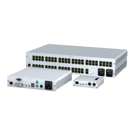
Das Zentralmodul Das Zentralmodul Das Zentralmodul ControlCenter-Compact ist die zentrale Komponente eines KVM- Matrixsystems. An das Zentralmodul werden die Target- sowie die Arbeitsplatzmo- dule angeschlossen. Die Aufschaltung eines Arbeitsplatzmoduls auf ein Target-Modul wird durch das Zentralmodul gesteuert. Lieferumfang 1 × Zentralmodul ControlCenter-Compact ... -
Page 8: Installation
Installation Installation HINWEIS: Die Skizzen zeigen die Variante ControlCenter-Compact-32C . Die verschie- denen Varianten unterscheiden sich in der Anzahl der Dynamic-Ports für den Anschluss der Arbeitsplatz- und Target-Module. Auf den folgenden Seiten wird die Installation der Komponenten des KVM-Systems beschrieben. HINWEIS: Stellen Sie bei der Standortwahl des Gerätes sicher, dass die zulässige Umgebungstemperatur (siehe Technische Daten auf Seite 27) in der unmittelbaren... -
Page 9: Installation Und Anschluss Der Arbeitsplatzmodule
Installation Installation und Anschluss der Arbeitsplatzmodule HINWEIS: Die maximale Distanz zwischen einem Arbeitsplatzmodul und dem Zen- tralmodul beträgt 140 Meter. Anschluss der Geräte des Arbeitsplatzes an die Arbeitsplatzmodule Schließen Sie die Gerätes des Arbeitsplatzes an die verschiedenen Arbeitsplatz- module an. Die erforderlichen Schritte werden in den mitgelieferten Handbüchern der Module beschrieben: Handbuch... -
Page 10: Installation Und Anschluss Der Target-Module
Installation Installation und Anschluss der Target-Module WICHTIG: Die maximale Distanz zwischen einem Target-Modul und dem Zentral- modul beträgt 140 Meter. Anschluss der Target-Computer an die Target-Module Schließen Sie die Target-Computer an die verschiedenen Target-Module an. Die erforderlichen Schritte werden in den mitgelieferten Handbüchern der Module beschrieben: Handbuch Artikelnummer... -
Page 11: Netzwerkschnittstellen
Installation Netzwerkschnittstellen HINWEIS: Die Konfiguration des Zentralmoduls über die Webapplikation Config Panel und der Einsatz der erweiterten Netzwerkfunktionalitäten (z. B. Authentifizierung gegenüber Verzeichnisdiensten, Zeitsynchronisation über einen NTP-Server, Netzfilter oder Syslog) erfordert eine Verbindung des Zentralmoduls mit einem (oder zwei) lokalen Netzwerk(en). WICHTIG: Falls Sie mit der Webapplikation die Konfiguration der Dynamic Ports geändert bzw. -
Page 12: Empfehlungen Zum Twisted-Pair-Kabel
Empfehlungen zum Twisted-Pair-Kabel Empfehlungen zum Twisted-Pair-Kabel Die Übertragung aller Signale des ControlCenter-Compact-Systems erfolgt über Twisted- Pair-Kabel der Kategorie 5e (oder höher). HINWEIS: Das Verbinden mehrerer Teilstrecken einer Kabelverbindung über Patchfelder und Anschlussdosen ist möglich. Die Einbindung aktiver Komponen- ten wie Netzwerk-Switches, Hubs oder Repeater, ist hingegen nicht zulässig. Die Datenübertragung ist mit handelsüblichen, standardkonformen Twisted-Pair- Kabeln der Kategorie 5e (oder höher) bis mindestens 80 Meter zuverlässig möglich. -
Page 13: Erstkonfiguration Der Netzwerkeinstellungen
Erstkonfiguration der Netzwerkeinstellungen Erstkonfiguration der Netzwerk- einstellungen Grundlegende Voraussetzung für den Zugriff auf die Webapplikation Config Panel und den Einsatz erweiterter Netzwerkfunktionalitäten ist die Konfiguration der Netz- werkeinstellungen des Zentralmoduls. Die erforderlichen Konfigurationseinstellungen können direkt an einem der eingerich- teten Arbeitsplätze durchgeführt werden. Konfiguration der Netzwerkschnittstellen Zur Anbindung des Gerätes an ein lokales Netzwerk sind die Einstellungen des Netzwerks zu konfigurieren. -
Page 14: Konfiguration Der »Globalen« Netzwerkeinstellungen
Erstkonfiguration der Netzwerkeinstellungen Operational Betätigen Sie die -Taste zur Auswahl des Betriebsmodus mode: der Schnittstelle bzw. Network A Network B Off: Netzwerkschnittstelle ausschalten. Static: Es wird eine statische IP-Adresse zugeteilt. Bezug der IP-Adresse von einem DHCP-Server. DHCP: IP address: Geben Sie die IP-Adresse der Schnittstelle an. -
Page 15: Verwendung Des Reset-Tasters
Verwendung des Reset-Tasters Verwendung des Reset-Tasters An der Frontseite des Zentralmoduls ist zwischen der Power-LEDs und der Identifica- tion-LED ein Reset-Taster platziert. Mit diesem Taster ist sowohl die Wiederherstellung der Standardeinstellungen als auch die temporäre Deaktivierung der Netzfilterregeln möglich. HINWEIS: Um die versehentliche Betätigung des Tasters zu vermeiden, ist dieser hinter einer Bohrung in der Frontblende platziert. -
Page 16: Temporäre Deaktivierung Der Netzfilterregeln
Verwendung des Reset-Tasters Temporäre Deaktivierung der Netzfilterregeln Im Auslieferungszustand des Zentralmoduls haben alle Computer im Netzwerk Zugriff auf die IP-Adresse des Gerätes (offener Systemzugang). Über die Webapplikation können Sie Netzfilterregeln erstellen, um den Zugang zum Gerät gezielt zu kontrollieren. Sobald eine Netzfilterregel erstellt ist, wird der offene Systemzugang deaktiviert und alle eingehenden Datenpakete mit den Netzfil- terregeln verglichen. -
Page 17: Konfiguration Der Dynamic Ports
Konfiguration der Dynamic Ports Konfiguration der Dynamic Ports WICHTIG: Ausführliche Informationen zur Konfiguration der Dynamic Ports finden Sie im Handbuch der Webapplikation Config Panel. Die verschiedenen Gerätevarianten der ControlCenter-Compact-Serie sind mit bis zu 80 Dynamic Ports zum Anschluss von Arbeitsplatz- und Target-Modulen ausgestattet. HINWEIS: Die Anzahl der Ports ist von der eingesetzten Variante des Matrix- switches ControlCenter-Compact abhängig. -
Page 18: Kompatibilitätsmodus
Konfiguration der Dynamic Ports Variante Up-Ports Down-Ports ControlCenter-Compact-16C 1 bis 4 5 bis 16 ControlCenter-Compact-32C 1 bis 8 9 bis 32 ControlCenter-Compact-48C 1 bis 12 13 bis 48 ControlCenter-Compact-64C 1 bis 16 17 bis 64 ControlCenter-Compact-80C 1 bis 20 21 bis 80 Kompatibilitätsmodus... -
Page 19: Erweiterung Des Kvm-Matrixsystems
Erweiterung des KVM-Matrixsystems Erweiterung des KVM-Matrixsystems Falls die Anzahl der Ports eines Matrixswitches für den gewünschten Einsatzzweck nicht ausreicht, können Sie mehrere Matrixswitches zu einem Verbund zusammen- fügen. Hierfür stehen folgende Technologien zur Verfügung: Kaskadierung (Standard) Für den Aufbau einer Kaskade schließen Sie an den Master-Matrixswitch einen Slave-Matrixswitch an. -
Page 20: Kaskadierung Eines Matrixswitches
Port-Modus zu beachten oder zu ändern. Die Ports der verschiedenen Gerätevarianten der ControlCenter-Compact-Serie sind ab Werk wie folgt für den Anschluss von über- bzw. untergeordneten Matrixswitches konfiguriert: Variante Up-Ports Down-Ports ControlCenter-Compact-16C 1 bis 4 5 bis 16 ControlCenter-Compact-32C 1 bis 8 9 bis 32 ControlCenter-Compact-48C... -
Page 21: Anschluss Eines Slave-Zentralmoduls
Erweiterung des KVM-Matrixsystems Anschluss eines Slave-Zentralmoduls So schließen Sie ein Slave-Zentralmodul an ein Mastergerät an: 1. Für jeden gleichzeitig auf das Slave-Zentralmodul aufschaltbaren Arbeitsplatz konfigurieren Sie je einen Dynamic Port als Up-Port 2. Verbinden Sie die soeben konfigurierten Up-Ports des Slave-Gerätes mit Down-Ports des Master-Gerätes. - Page 22 Erweiterung des KVM-Matrixsystems 4. Wählen Sie die Zeile Cascade mode und betätigen Sie die -Taste zur Auswahl einer der aufgelisteten Optionen: Auto: Das Zentralmodul bestimmt selbstständig, ob er im Master- oder Slave-Modus arbeitet. Master: In diesem Betriebsmodus können an Dynamic Ports, die für den Anschluss von Target-Modulen konfiguriert sind, ausschließlich Arbeitsplatzmodule angeschlossen werden.
-
Page 23: Erweiterung Der Schaltbaren Signale
Erweiterung der schaltbaren Signale Erweiterung der schaltbaren Signale Sie können die schaltbaren Signale eines Rechners bzw. Arbeitsplatzes wahlweise durch Kanal-Gruppierung oder durch Stacking erweitern. BEISPIEL: Für die Übertragung eines zweiten Videosignals und eines USB 2.0- Signals eines Rechners schließen Sie zusätzlich zum Rechnermodul ein zwei- DVI-CPU tes Modul... -
Page 24: Erweiterung Durch Port-Gruppierung
Erweiterung der schaltbaren Signale Durch die Verwendung von Pools können Sie bis zu vier Benutzern gleichzeitig Zugriff auf den USB 2.0-/RS 232-Kanal gewähren. Hierfür wählt der Matrixswitch bei der Aufschaltung automatisch ein freies Gerät aus dem Pool. Durch die Zuordnung mehrerer Kanäle zu einem Arbeitsplatz oder einem Rechner erstellen Sie eine sogenannte Kanal-Gruppierung. -
Page 25: Module Einer Kanal-Gruppierung Hinzufügen Oder Entfernen
Erweiterung der schaltbaren Signale 7. Klicken Sie auf zu Speicherung der neuen Kanal-Gruppierung. HINWEIS: Die in der Kanal-Gruppierung enthaltenen Arbeitsplatz- oder Rechner- module werden in der Auflistung der Module mit einem Plus-Zeichen hinter dem Namen angezeigt. Klicken Sie auf das Symbol, um die Auflistung der Module einzusehen. Module einer Kanal-Gruppierung hinzufügen oder entfernen So fügen Sie Module einer Kanal-Gruppierung hinzu oder löschen die bestehende Zuordnung eines Moduls:... -
Page 26: Eine Kanal-Gruppierung Löschen
Erweiterung der schaltbaren Signale 5. Klicken Sie auf zu Speicherung der neuen Kanal-Gruppierung. HINWEIS: Die in der Kanal-Gruppierung enthaltenen Arbeitsplatz- oder Rechner- module werden in der Auflistung der Module mit einem Plus-Zeichen hinter dem Namen angezeigt. Klicken Sie auf das Symbol, um die Auflistung der Module einzusehen. Eine Kanal-Gruppierung löschen So löschen Sie eine Kanal-Gruppierung: 1. -
Page 27: Erweiterung Durch Stacking
Erweiterung der schaltbaren Signale Erweiterung durch Stacking Im Stacking-Modus werden mehrere Matrixswitches parallel geschaltet. Hierfür verbinden Sie die Matrixswitches über die -Ports und vergeben den Matrixswitches fortlaufende Bus-Adressen. Jeder Stack-Matrixswitch besteht aus einem Matrixswitch, der den KVM Main Channel bereitstellt. Ergänzt wird er durch maximal 9 Satelliten-Matrixswitches. Die Satelli- ten können wahlweise als Video Channel oder als... -
Page 28: Bus-Adresse Eines Matrixswitches Einstellen
Erweiterung der schaltbaren Signale Bus-Adresse eines Matrixswitches einstellen Der Primary-Matrixswitch schaltet automatisch die Stack-Matrixswitches auf den gleichen Port, den der Anwender am Primary-Matrixswitch aufschaltet. Um dies zu gewährleisten, ist die korrekte Einstellung der Bus-Adresse in den ein- zelnen Matrixswitches erforderlich. So ändern Sie die Bus-Adresse eines Matrixswitches: 1. -
Page 29: Statusanzeigen
Statusanzeigen Statusanzeigen LEDs an der Frontseite Die LEDs an der Frontseite des Zentralmoduls geben Ihnen die Möglichkeit, den Betriebsstatus des Systems jederzeit zu kontrollieren: Bereich Status Bedeutung Power Red. Das Netzteil ist eingeschaltet und liefert die erforderliche Spannung. Das Netzteil ist ausgeschaltet oder die Verbindung mit dem Stromnetz nicht hergestellt. - Page 30 Statusanzeigen LEDs an der Rückseite Auf der Rückseite des Zentralmoduls befinden sich an jeder RJ45-Schnittstelle zusätzliche Status-LEDs. Diese LEDs haben folgende Funktion: Schnittstelle Status Bedeutung Network gelb Verbindung aktiv grün blinkt Aktivität auf der Netzwerkschnittstelle festgestellt Dynamic Port gelb Status-Modus: Ein Benutzer ist am Arbeitsplatzmodul eingeloggt bzw.
-
Page 31: Technische Daten
Dimensionen (B × H × T): siehe spezifische Eigenschaften Einsatzumgebung Temperatur: +5 bis +40 °C Luftfeuchte: < 80%, nicht kondensierend Konformität CE, RoHs Spezifische Eigenschaften der Geräte CONTROLCENTER-COMPACT-16C Schnittstellen Dynamic Ports: 16 × RJ45-Buchse Hauptstrom- Stromaufnahme: 100-240V/60-50Hz, 0.6-0.4A versorgung Redundante Stromaufnahme: 100-240V/60-50Hz, 0.6-0.4A... - Page 32 Technische Daten CONTROLCENTER-COMPACT-32C Schnittstellen Dynamic Ports: 32 × RJ45-Buchse Hauptstrom- Stromaufnahme: 100-240V/60-50Hz, 0.7-0.4A versorgung Redundante Stromaufnahme: 100-240V/60-50Hz, 0.7-0.4A Stromversorgung Gehäuse Dimensionen (B × H × T): 435 × 44 × 211 mm CONTROLCENTER-COMPACT-48C Schnittstellen Dynamic Ports: 48 × RJ45-Buchse Hauptstrom- Stromaufnahme: 100-240V/60-50Hz, 0.8-0.4A versorgung...
-
Page 34: About This Manual
About this manual This manual has been carefully compiled and examined to the state-of-the-art. G&D neither explicitly nor implicitly takes guarantee or responsibility for the qual- ity, efficiency and marketability of the product when used for a certain purpose that differs from the scope of service covered by this manual. - Page 35 Table of contents Contents Safety instructions .................... 1 The »ControlCenter-Compact« KVM matrix system ........2 Expanding a KVM matrix system ..............2 The central module ................... 3 Package contents ....................3 Required accessories ..................3 Installation ....................... 4 Power supply ....................4 Installing and connecting user modules ..............
- Page 36 Table of contents Expanding the system through stacking ............23 Connecting a stack matrix switch ..............23 Adjusting the bus address of matrix switches ..........24 Status displays ....................25 Technical data ....................27 General features of the series ................27 Specific features of the devices ................
-
Page 37: Safety Instructions
Safety instructions Safety instructions Please read the following safety instructions carefully before you start operating the G&D product. The instructions well help in avoiding damages to the product and in preventing possible injuries. Keep this manual handy for all persons who will be using this product. Follow all warnings or operating instructions which are on the device or stated in this user manual. -
Page 38: The »Controlcenter-Compact« Kvm Matrix System
You can now operate the accessed computer with console keyboard and console mouse. The ControlCenter-Compact series includes the following variants: Variant Dynamic ports to connect modules ControlCenter-Compact-16C 16 × RJ45 socket (CAT) ControlCenter-Compact-32C 32 × RJ45 socket (CAT) ControlCenter-Compact-48C 48 ×... -
Page 39: The Central Module
The central module The central module The central module ControlCenter-Compact is the central device within a KVM matrix system. The target and user modules are connected to the central module. The central module controls the access of a user module to a target module. Package contents ... -
Page 40: Installation
Installation Installation NOTE: The following drawings refer to the ControlCenter-Compact-32C . The different variants vary in the number of dynamic ports to connect user modules and target modules. The following pages describe the installation of the devices of the KVM system. NOTE: When choosing a place for the device, please ensure to comply with the ambient temperature limit (see Technical data on page 27) close to the device. -
Page 41: Installing And Connecting User Modules
Installation Installing and connecting user modules IMPORTANT: You can place user modules up to 140 metres away from the central module. Connecting console devices to user modules Connect the console devices to the different user modules. The steps required to connect these devices are described in the manual supplied with the modules: Manual Order number... -
Page 42: Installing And Connecting Target Modules
Installation Installing and connecting target modules IMPORTANT: You can place target modules up to 140 metres away from the central module. Connecting target computers to target modules Connect the target computer to the different target modules. The steps required to connect these devices are described in the manual supplied with the modules: Manual Order number... -
Page 43: Network Interfaces
Installation Network interfaces NOTE: You need to connect the central module to one or two local networks to configure the central module via Config Panel web application and use the enhanced network functionalities (for example authentication against directory services, time sync via NTP server, netfilter or syslog). IMPORTANT: If you change the configuration of the Dynamic Ports in the web appli- cation, or if you enable the signalling of the Dynamic Ports modes, end the connec-... -
Page 44: Recommended Twisted Pair Cables
Recommended twisted pair cables Recommended twisted pair cables The transmission of all signals of the ControlCenter-Compact system is carried out through one twisted pair cable (category 5e or better). NOTE: It is permitted to connect several segments of a cable connection with patch panels and connection ports. -
Page 45: Initial Configuration Of Network Settings
Initial configuration of network settings Initial configuration of network settings Accessing the Config Panel web application and using the expanded network functions requires you to configure the network settings of the matrix switch. You can configure the network settings by using one of the new consoles. Configuring network ports A central module, which is integrated into the network, can only be addressed after the network ports are configured. -
Page 46: Configuring The «Global» Network Settings
Initial configuration of network settings Operational Press to select the operating mode of the interface mode: Network A Network B Off: switches off network interface. Static: uses static settings. obtains the settings from a DHCP server. DHCP: IP address: Enter the interface IP address. -
Page 47: Reset Button
Reset button Reset button The Reset button is placed between the Power LEDs and the Identification LED on the front panel of the central module. This button allows you to reset the default settings and disable the netfilter rules. NOTE: To prevent you from pressing the button by accident, you are required to use a thin, pointed object for pressing the button. -
Page 48: Disabling The Netfilter Rules Temporarily
Reset button Disabling the netfilter rules temporarily In the default status of the central module, all network computers have access to the extender’s IP address (open system access). The web application enables you to create netfilter rules to control the access to the device. -
Page 49: Configuring Dynamic Ports
Configuring dynamic ports Configuring dynamic ports IMPORTANT: The manual of the web application Config Panel provides detailed information about the configuration of dynamic ports. The different device variants of the ControlCenter-Compact series provide up to 80 dynamic ports for the connection of user modules and target modules. NOTE: The number of ports depends on ControlCenter-Compact variant. -
Page 50: Compatibility Mode
Configuring dynamic ports Variant Up ports Down ports ControlCenter-Compact-16C 1 to 4 5 to 16 ControlCenter-Compact-32C 1 to 8 9 to 32 ControlCenter-Compact-48C 1 to 12 13 to 48 ControlCenter-Compact-64C 1 to 16 17 to 64 ControlCenter-Compact-80C 1 to 20... -
Page 51: Expanding The Kvm Matrix System By Cascading
Expanding the KVM matrix system by cascading Expanding the KVM matrix system by cascading If the number of ports of a matrix switch is not sufficient for the desired purpose, you can combine multiple matrix switches. For this, we provide the following tech- nologies: Cascading (default) To establish a cascade, connect a slave matrix switch to the master matrix switch. -
Page 52: Cascading A Matrix Switch
By default, the ports of the different variants of the ControlCenter-Compact series are configured to connect both master and slave matrix switches: Variant Up ports Down ports ControlCenter-Compact-16C 1 to 4 5 to 16 ControlCenter-Compact-32C 1 to 8 9 to 32... -
Page 53: Connecting A Slave Central Module
Expanding the KVM matrix system by cascading Connecting a slave central module How to connect a slave central module to a master device: 1. Configure the same number of dynamic ports as up ports as consoles that you want to allow to simultaneously access the slave central module. 2. - Page 54 Expanding the KVM matrix system by cascading 4. Select the Cascade mode entry and press to choose one of the listed options: Auto: The central module defines if it works in the master or slave mode. Master: In this operating mode, you can only connect user modules to Dynamic Ports that are configured for the connection of target mod- ules.
-
Page 55: Expanding Switchable Signals
Expanding switchable signals Expanding switchable signals You can expand a computer’s or a console’s switchable signals either through chan- nel grouping or stacking. EXAMPLE: To transmit a second video signal and a USB 2.0 signal of the same computer, in addition to the DVI-CPU computer module, connect a second DVI-CPU... -
Page 56: Expanding Through Port Grouping
Expanding switchable signals By using pools, you can grant up to four users the right to access the USB 2.0/ RS 232 channel at the same time. For this, the matrix switch selects an available device from the pool after switching. Assigning multiple channels to a console or computer creates a channel group. -
Page 57: Adding Or Deleting Modules From A Channel Group
Expanding switchable signals Adding or deleting modules from a channel group How to add modules to or delete them from a channel group: 1. In the directory tree, click KVM matrix systems > [Name] > User modules Target modules 2. Right-click a user module or a computer module that is already assigned to the channel group to which you want to add another module to orfrom which you want to delete a module. -
Page 58: Deleting A Channel Group
Expanding switchable signals Deleting a channel group How to delete a multichannel configuration: 1. In the directory tree, click KVM matrix systems > [Name] > User modules Target modules 2. Right-click a user or computer module you want to delete from a channel group. 3. -
Page 59: Expanding The System Through Stacking
Expanding switchable signals Expanding the system through stacking In Stacking mode, you can switch multiple matrix switches at the same time. For this, connect the matrix switches via ports and assign them with continuous bus addresses. Each stacking matrix switch consists of a matrix switch that provides the KVM Main . -
Page 60: Adjusting The Bus Address Of Matrix Switches
Expanding switchable signals Adjusting the bus address of matrix switches The primary matrix switch automatically makes the stack matrix switches access the same port that the user accesses at the primary matrix switch. This requires the correct setting of the bus address in the individual matrix switches. How to change the bus address of a matrix switch: 1. -
Page 61: Status Displays
Status displays Status displays LEDs at the front panel The LEDs on the front panel of the matrix switch show the system’s operating status: Section Status Meaning Power Red. The power pack is turned on and supplies the required volt- age. - Page 62 Status displays LEDs at the back panel The back panel of the matrix switch provides an additional status LED at each RJ45 interface. The LEDs have the following function: Interface Status Meaning Network yellow on Active connection green blinking Activity at network interface Dynamic Port yellow on ...
-
Page 63: Technical Data
see specific features Operational Temperature: +5 to+40 °C environment Air humidity: < 80%, non-condensing Conformity CE, RoHs Specific features of the devices ControlCenter-Compact-16C Interfaces Dynamic ports: 16 × RJ45 socket Main power supply Current consumption: 100-240V/60-50Hz, 0.6-0.4A Redundant Current consumption: 100-240V/60-50Hz, 0.6-0.4A... - Page 64 Technical data ControlCenter-Compact-32C Interfaces Dynamic ports: 32 × RJ45 socket Main power supply Current consumption: 100-240V/60-50Hz, 0.7-0.4A Redundant Current consumption: 100-240V/60-50Hz, 0.7-0.4A power supply Housing Dimensions (W × H × D): 435 × 44 × 211 mm ControlCenter-Compact-48C Interfaces Dynamic ports: 48 ×...
- Page 68 Das Handbuch wird fortlaufend aktualisiert und im Internet veröffentlicht. The manual is constantly updated and available on our website. http://gdsys.de/A9100282 Guntermann & Drunck GmbH Dortmunder Str. 4a 57234 Wilnsdorf Germany http://www.GDsys.de sales@GDsys.de...
Need help?
Do you have a question about the ControlCenter-Compact-16C and is the answer not in the manual?
Questions and answers