Table of Contents
Advertisement
Quick Links
Blue Point
Instruction
I
www.BPEsolutions.com
Engineering
Pointing the Way to Solutions!
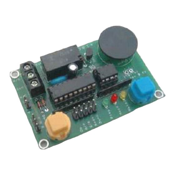
Puppeteer Plus Board
Puppet - II+
Controller
(BPE No. PCA-0001)
Servo Position Adjustment
EEPROM
Relay Connection
Digital Button
Power Connection 5 Vdc
LED
Relay LED
Record LED
Playback LED
GO Button
The Puppeteer plus board provides up to 4 minutes of recording and playback time for one servo channel
and one digital (relay) output channel. The board supports sequential recording functions, daisy chaining
and loop playback with variable inter-loop timing and automatic start-up positioning.
Board Connections
Power Supply Header
The Puppeteer plus board requires +5V DC supply at currents up to 0.5 amps depending on servo used.
Servo Header
Three pin header to connect to standard servos- observe polarity of servo connection wire (R,B,W)
The Puppeteer plus board generates pcm signals between 0.5 and 2.5msec long repeated every 20msecs.
Note: Most servos are generally only rated for 1-2msec pulses so care should be taken at the extreme
ends of the travel to ensure the servo motor is not damaged by the extreme travel.
3-Way Terminal Block
Switched relay outputs. The relay is rated at 24V DC @ 1 Amp
(NO, Comm, NC terminal connections)
Controls
Go Switch Button
Press and release to record the servo and digital(relay) actions.
Press and release to initiate playback modes.
Go Pins
Used for daisy-chaining multiple Puppeteer plus board - connect subsidiary module Go pins to the sync
output pins.
R/P Pins
Selects either R ecord mode (jumper IN place) or P layback mode (jumper OUT).
S/R Pins
Selects either loop playback R epeat (Jumper OUT) or Single playback (Jumper IN )
Reset Pins
Resets the Puppeteer plus board. (Briefly short the Reset jumper pin pair to reset the controller)
Advertisement
Table of Contents

Related Manuals for Blue Point Engineering Puppeteer Plus


Summary of Contents for Blue Point Engineering Puppeteer Plus
- Page 1 Playback LED GO Button The Puppeteer plus board provides up to 4 minutes of recording and playback time for one servo channel and one digital (relay) output channel. The board supports sequential recording functions, daisy chaining and loop playback with variable inter-loop timing and automatic start-up positioning.
- Page 2 ON to ensure a smooth continuation of actions. Module newly powered up: Playback the stored moves – this will load into the Puppeteer plus board the location of the last move. Proceed as per the standard follow-on recording above.
- Page 3 Puppeteer Plus Board Servo Positions Standard +5 Volt dc R/C Servo Caution Check Correct Servo Connection Caution Power Check Correct Connection Polarity (+/-). 5Vdc BLACK Wire R/C Servo Connection RED Wire Relay Connections GO Button 24V DC @ 1 Amp...
- Page 4 Wire Terminal RED Wire Power Connection 5Vdc + Vdc - Vdc Relay Connections 24V DC @ 1 Amp Relay Wall Plug Power Supply 5 Vdc @ 0.5 Amp Wall Power Adapter Copyright © 2002 Blue Point Engineering, All Rights Reserved...
- Page 5 Terminal Relay * In no event shall Blue Point Engineering be liable for any claim for incidental, consequential damages, or any injuries sustained due to the use of or improper use of this circuit. This circuit should NOT be used for any applications that could cause injury, dangerous / hazardous situations or consequential damages.
- Page 6 Puppet Plus Controller Board Puppeteer Plus Board Optional Small DC Motor Control Mode Relay Relay Connections 24 Volts DC @ 1 Amp Wire Connection 12 Volt DC Terminal Power Supply Red Wire -Gnd Black Wire MOTOR POWER Motor 12 Volt DC...
- Page 7 Black Wire Red Wire 9 Volt dc Power Supply Resistors 150 Ohm 1/8 Watt Blue LED's 2.3 Vdc 50 mA Copyright © 2002 Blue Point Engineering, All Rights Reserved Custom Equipment, Unique Electronic Products www.BPEsolutions.com Blue Point Engineering Phone (303) 651-3794...
Need help?
Do you have a question about the Puppeteer Plus and is the answer not in the manual?
Questions and answers