
Related Manuals for Ceetec IP250

Summary of Contents for Ceetec IP250
- Page 1 Page 1 of 45 OPERATORS MANUAL – PAINTING MACHINE IP250 Manual version 03. Applicable from 09/09 2011. Made by: Ceetec A/S Industrivej 7 DK-5580 Nr. Aaby Tel.: +45 6442 1473 e-mail: info@ceetec.dk...
-
Page 2: Table Of Contents
Page 2 of 45 1 Table of contents Table of contents............................2 General terms of use ..........................4 Safety provisions ............................4 Special training requirements......................4 Limitations to use ........................... 4 Personal protective equipment....................... 5 Clothing ............................5 Cleaning, service and maintenance ....................5 Screening ............................ - Page 3 Page 3 of 45 12.1 Toothed belt for motor – feed roller ....................31 12.2 Toothed belt for forward drive ...................... 32 12.3 Toothed belt for vertical brushes ....................33 12.4 Toothed belt for horizontal brushes....................34 Spare parts overview ..........................35 EC Declaration of conformity ........................
-
Page 4: General Terms Of Use
The machine may only be used for the purpose agreed in the order confirmation. If the machine is used for other purposes, or if structural changes are made then Ceetec cannot guarantee the safety of the machine and the warranty will be null and void. -
Page 5: Personal Protective Equipment
Page 5 of 45 Personal protective equipment Necessary safety equipment/personal protective equipment must be used. Gloves, eye protection and safety shoes are recommended. Respiratory protection is recommended if there are harmful substances present during processing. See data sheet from the paint/varnish supplier and follow his directions. Clothing The operator must wear appropriate work clothing. -
Page 6: General Information
Page 6 of 45 4 General information Manufacturer Ceetec A/S Industrivej 7 DK – 5580 Nr. Aaby Tel.: +45 64 42 14 73 e-mail: info@ceetec.dk Machine information Machine type: Painting machine Type designation: IP250 Type no.: Capacity Max. item dimensions Width 250mm x height 100mm Min. -
Page 7: Description Of The Machine
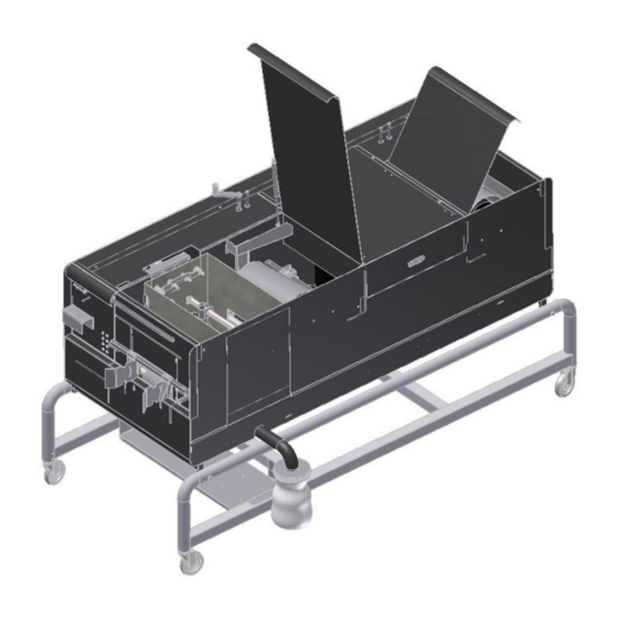
Page 7 of 45 5 Description of the machine Ceetec IP250 is made to treat wood with wood protection products (water and oil based). The machine can be used for rough, planed and profiled wood. The item is led by driving rollers past a set of nozzles which add an overdose of wood protection/paint to the item. - Page 8 Page 8 of 45 Layout drawing: 1. Operator, intake 7. Vertical brushes 12. Nozzle box w/nozzle 2. Intake 8. Horizontal brushes pipe 3. Intake guide 9. Outlet 13. Overpressure valve 4. Feed roller 10. Operator, outlet 14. Suction filter 5. Filter bag 11.
-
Page 9: Mounting
Page 9 of 45 Mounting The mechanical mounting must be finished before the electrical can be started. Make sure the mounted screens mounted correctly and are in order. If the screens are not in place there may be danger of personal injury in connection with moving/rotating parts. Lift and handling The machine must be lifted with a forklift truck. -
Page 10: Dismounting/Disposal
Page 10 of 45 Dismounting/disposal The electrical connection must be disconnected by a licensed electrician in accordance with current national rules. The machine must be disassembled and disposed of in accordance with the national rules in force at the time. -
Page 11: Preparation Of The Machine
Page 11 of 45 6 Preparation of the machine 1. The machine is placed on an even and firm surface, and the wheels are locked to ensure the machine cannot move. 2. The electricity is connected. 3. Adapter for filter bag (1) is mounted on the drain pipe and the filter bag (2) is mounted to this. The container with wood protection is placed under the filter bag, and the suction (3) and overpressure hose (3) is placed in the container. -
Page 12: Operation
In case of a shutdown it must be ensured that the plant has stopped completely before attempting to remedy the error. Check the setup. If there is no error then call a service employee or contact Ceetec. Operation Before start-up the supplier instruction manual for the paint product must be read in order to make sure any safety precautions in connection with the use of the product can be adhered to. -
Page 13: Control - Normal Operation
Page 13 of 45 8 Control – normal operation During normal operation the machine has an operator at each end. An operator who pushes the wood items into the machine and another operator who takes the items once they have been painted/treated and come out of the machine. -
Page 14: Setting And Test Run
Page 14 of 45 Setting and test run Before any start of continuous operation an individual setting and test run of the machine must be carried out. Setting of the machine is done the following way: 1. Disconnect the power supply 2. - Page 15 Page 15 of 45 13. Connect power 14. Start the pump. The electrical pump is started on the button “PUMP” which is turned to 1. The air- powered pump is started by connecting air and possibly regulating it. 15. Carefully open the main tap (4) in order to put paint in the nozzle box. 16.
-
Page 16: Adjustment/Setting Of The Machine
Page 16 of 45 9 Adjustment/setting of the machine Do not make adjustments while the machine is running. For every adjustment it must be ensured that the machine is: Free of items (empty) Not moving (emergency stop is activated) Power supply is disconnected We recommend that operators use rubber gloves and eye protection during work. -
Page 17: Brushes And Screens
Page 17 of 45 Brushes and screens The rotating brushes distribute the liquid evenly and brush away the superfluous liquid/paint. The brushes are similar and made from durable nylon. The brushes are easy to mount and dismount for cleaning. The setting of the brushes depends on the treatment and profile of the item. The setting of the brush pressure on the horizontal brushes is carried out by turning the four spindles (8) with the handle. -
Page 18: Forward Drive
Page 18 of 45 Forward drive The forward drive pulls the item through the machine. The back-pressure roller is regulated by turning the spindle with the handle. Turning clockwise: The back-pressure roller is lifted Turning counter-clockwise: The back-pressure roller is lowered The back-pressure roller is brought in contact with the item and tightened app. -
Page 19: Dismantling Side Plate And Opening Lid
Page 19 of 45 Dismantling side plate and opening lid Note that the pump can be activated even if the side plate is dismantled. The side plate (1) on the right side of the machine is mounted with locks which make it easier to dismantle it without the use of tools. -
Page 20: Cleaning
Page 20 of 45 10 Cleaning We recommend that operators use rubber gloves and eye protection during work. Also check the product sheet/supplier user manual for requirements to other protective equipment. For safety reasons it is important to keep signs and operating handles clean and free from paint. After finished operation and at colour change it is important that the machine is cleaned thoroughly. -
Page 21: Maintenance
Page 21 of 45 11 Maintenance For any service and maintenance task it must be ensured that the machine is: Free of items (empty) Not moving (emergency stop is activated) Power supply is disconnected Never try to touch parts of the machine during operation 11.1 Regular maintenance In general the machine must be checked and lubricated at least 12 times a year or after approximately 100... - Page 22 Page 22 of 45 Grease specifications: We recommend multi-purpose grease with good water resistance, like e.g. FINA LICAL EP 2, or a similar product. There is free choice between grease manufacturers. Do not mix synthetic grease and mineral grease. Choice of unmarketable grease may lead to fire, corrosion or insufficient maintenance of the unit with subsequent reduced life.
-
Page 23: Toothed Belts
Page 23 of 45 11.3 Toothed belts All the machine’s rotating parts are driven by toothed belts. All toothed belts are equipped with tension pulleys and must be checked for the first time after app. 50 hours operation. After this the belts must be checked at least once a year or after 1,700 hours operation. 11.3.1 Toothed belt for motor –... -
Page 24: Toothed Belt For Forward Drive
Page 24 of 45 11.3.2 Toothed belt for forward drive Tensioning of belt for forward drive is carried out the following way: · The side plate is dismantled · Bolt on tension pulley (1) is loosened · The tension pulley is displaced until belt (2) has sufficient tension ·... -
Page 25: Toothed Belt For Vertical Brushes
Page 25 of 45 11.3.3 Toothed belt for vertical brushes Tensioning of belt for vertical brushes is carried out the following way: · The fixed lid is dismantled · 4 bolts on motor (1) are loosened · Motor is displaced until belt (2) has sufficient tension ·... -
Page 26: Toothed Belt For Horizontal Brushes
Page 26 of 45 11.3.4 Toothed belt for horizontal brushes The belt (1) which drives the machine’s horizontal brushes is tensioned with a spring system (2) which makes tensioning of the belt unnecessary. However, we recommend checking the belt for wear/breaks regularly and possibly replace it. -
Page 27: Lubricating Guides/Spindles For Brush Arrangements
Page 27 of 45 11.4 Lubricating guides/spindles for brush arrangements 1. Hardened axles + spherical bushing: 4 on horizontal brush arrangements and 2 on vertical brush arrangements: Lubricate with spray grease every 3 months or after 500 operating hours. We suggest using a spray with grease of the type: NKL Molycote chain grease. -
Page 28: Motors, Gear And Pump
The motor must be maintained in accordance with the supplier’s directions. Gear (pump): (If the machine is equipped with a Ceetec membrane pump) Carry out monthly checks of oil level on gear. The gear must be maintained in accordance with the supplier’s directions. - Page 29 Page 29 of 45 Troubleshooting Fault Possible cause Remedy The machine is not connected to Connect power supply the power supply A. Pump/Forward drive/brushes Main switch is disconnected Main switch is set to position 1 are not starting Check frequency converter in There may be thermal failure electrical cabinet Power supply for motor for...
- Page 30 Page 30 of 45 Adjust the setting. Motor is overloaded due to back- E. Motor for forward drive drops Wait app. 10 min. before the pressure roller and/or guide being motor for the forward drive is set too closely to the item reset.
-
Page 31: Replacing Spare Parts
Page 31 of 45 12 Replacing spare parts All replaceable parts can be accessed easily when the side plate, shield on the back lid and/or the bottom protection cover is dismounted. When replacements have been made the assembly must take place in reverse order. DO NOT START the machine until all protective devices are mounted. -
Page 32: Toothed Belt For Forward Drive
Page 32 of 45 12.2 Toothed belt for forward drive Replacement of belt for forward drive is carried out the following way: · Bolt on tension pulley (1) is loosened · The tension pulley is loosened until the belt (2) is loose ·... -
Page 33: Toothed Belt For Vertical Brushes
Page 33 of 45 12.3 Toothed belt for vertical brushes Replacement of belt for vertical brushes is carried out the following way: · The fixed lid is dismounted · 4 bolts on motor (1) are loosened · Motor is displaced (belt is loosened) and the belt (2) is dismounted ·... -
Page 34: Toothed Belt For Horizontal Brushes
Page 34 of 45 12.4 Toothed belt for horizontal brushes Replacement of belt for horizontal brushes is carried out the following way: · Pull off the belt (tensioning of the belt is spring loaded, and thus the belt can be pulled off without loosening tension pulleys or similar) ·... -
Page 35: Spare Parts Overview
Page 35 of 45 13 Spare parts overview See general views after the list Item no. Description Amount/machine Picture 9021-20500 Ceetec IP250 9015-20535 Intake guide – 1 set 9012-50584 Spindle for overpressure roller Chain wheel for overpressure 9012-20515 roller 9021-20501... - Page 36 Page 36 of 45 Item no. Description Amount/machine Picture 9011-20567 Brush, 130 mm, nylon 9011-20600 Screen over brushes Screen for groove in side plate – 9021-20508 long, complete Screen for groove in side plate – 9021-20509 short, complete 9012-20360 Sling disc - Ø25 without pin 9011-20454 Simmer ring for brush axle 9011-20662...
- Page 37 Page 37 of 45 Item no. Description Amount/machine Picture Brush arrangement, vertical, right, 9021-20523 complete Brush arrangement, vertical, left, 9021-20524 complete 9021-20525 Toothed belt for vertical brushes Hardened axle for vertical brush 9021-20526 arrangement Trapezoidal spindle for vertical 9021-20527 brush arrangement Ball bearing for trapezoidal spindle 9021-20528 for brush arrangement...
- Page 38 9011-20590 Suction filter, complete 9011-20542 Overpressure valve, complete 9011-20517 Filter bag, 600 my (std.) 9021-20555 Belt set IP250, complete Distributor chamber IP250, 9021-20556 complete 9011-75050 Teflon foil for box (1 meter) 9012-50592 Adapter head for filter 2" 9021-20557...
- Page 39 Page 39 of 45 Spare parts image A...
- Page 40 Page 40 of 45 Spare parts image B...
- Page 41 Page 41 of 45 Spare parts image C...
- Page 42 Page 42 of 45 Spare parts image D...
- Page 43 Page 43 of 45 Spare parts image E...
- Page 44 Page 44 of 45 Spare parts image pump Pos. No. Amount per Designation machine 9011-20720 Membrane pump, complete, with motor 9011-20721 Pump lid with non-return valve 9011-20722 Membrane set 9011-20723 Non-return valve, stainless 9011-20724 Pump rod/slider with pressure plates 9011-20727 Support bearing 6008 9011-20728 Guide bearing...
-
Page 45: Ec Declaration Of Conformity
Page 45 of 45 14 EC Declaration of conformity The CE declaration of conformity for the machine is enclosed as an appendix.
Need help?
Do you have a question about the IP250 and is the answer not in the manual?
Questions and answers