Table of Contents
Advertisement
Quick Links
Advertisement
Table of Contents
Troubleshooting

Related Manuals for Mold-Masters Hot Runner


Summary of Contents for Mold-Masters Hot Runner
- Page 1 Hot Runner Hot Runner User Manual User Manual version 31 Original Instructions...
-
Page 3: Table Of Contents
1.2 Documentation ....................1-1 1.3 Release Details ....................1-1 1.4 Warranty ......................1-2 1.5 Returned Goods Policy ..................1-2 1.6 Movement or Resale of Mold-Masters Products or Systems ......1-2 1.7 Copyright ......................1-2 1.8 Units of Measure and Conversion Factors ............1-3 Section 2 - Global Support ..........2-1 2.1 Corporate Offices....................2-1... - Page 4 5.20 Heater Plates Installation ................5-44 5.21 Inlet Components Installation .................5-46 5.21.1 Back Plate Installation ................5-46 5.21.2 Center Heater Installation ..............5-47 5.21.3 Three Piece Center Heater Installation ..........5-47 5.21.4 Inlet Extension Installation ..............5-48 © 2020 Mold-Masters (2007) Limited. All Rights Reserved. Hot Runner User Manual...
- Page 5 10.4.1 5500 Series Only ...................10-3 10.4.2 6X00 Series and 7100 Series ..............10-3 10.5 Cylinder Top Assembly ...................10-4 10.6 Valve Pin Finishing of Tip ................10-4 10.6.1 5500 Series ....................10-4 10.6.2 6X00 Series ...................10-6 Hot Runner User Manual © 2020 Mold-Masters (2007) Limited. All Rights Reserved.
- Page 6 Section 12 - SeVG Plus Actuator ......... 12-1 12.1 Introduction .....................12-1 12.2 SeVG Plus Actuator Models ................12-1 12.3 SeVG Plus Actuator in Hot Runner Systems ..........12-1 12.4 SeVG Plus Model Options ................12-2 12.4.1 SE40-20 Actuator - Non Cooled ............12-2 12.4.2 SE40-20C Actuator - Cooled ..............12-3 12.4.3 SE20-15 Actuator - Non Cooled ............12-4...
- Page 7 14.6.6 Assemble the Nut and Lock Magnet Holder ..........14-9 14.6.7 Assemble the Valve Pin into the Valve Pin Holder .........14-9 14.6.8 O-Ring Installation into Valve Pin Holder ..........14-10 Hot Runner User Manual © 2020 Mold-Masters (2007) Limited. All Rights Reserved.
- Page 8 Section 17 - Accu-Line™ ..........17-1 17.1 Accu-Line™ with Valve Bushing ..............17-1 17.1.1 Accu-Line™ with Valve Bushing - Pre-Assembly .....................17-2 17.2 Accu-Line™ with Valve Bushing - Assembly ..........17-2 © 2020 Mold-Masters (2007) Limited. All Rights Reserved. Hot Runner User Manual...
- Page 9 19.4 Melt-CUBE Design B ..................19-19 19.4.1 Melt-CUBE Design B: Components .............19-19 19.4.3 Melt-CUBE Design B: Inspection ............19-20 19.4.2 Melt-CUBE Design B: Maintenance Toolkit .........19-20 19.4.4 Melt-CUBE Design B: Cleaning ............19-21 Hot Runner User Manual © 2020 Mold-Masters (2007) Limited. All Rights Reserved.
- Page 10 20.6.13 Parts Sticking to Core ................20-17 20.6.14 Short Parts ..................20-18 20.6.15 Sinks or Voids ..................20-19 20.6.16 Splay ....................20-20 20.6.17 Streaks ....................20-21 20.6.18 Stringing .....................20-22 20.6.19 Warped Parts ..................20-23 20.6.20 Weld Lines ..................20-24 © 2020 Mold-Masters (2007) Limited. All Rights Reserved. Hot Runner User Manual...
- Page 11 Section 21 - Glossary of Terms ........21-1 Index ................... Hot Runner User Manual © 2020 Mold-Masters (2007) Limited. All Rights Reserved.
-
Page 12: Section 1 - Introduction
Section 1 - Introduction The purpose of this manual is to assist users in the integration, operation and maintenance of a Hot Runner. This manual is designed to cover most system configurations. If you need additional information specific to your system, or information in another language, please contact your representative or a Mold-Masters office. -
Page 13: Returned Goods Policy
Mold- Masters representative. 1.5 Returned Goods Policy Please do not return any parts to Mold-Masters without pre-authorization and a return authorization number supplied by Mold-Masters. Our policy is one of continuous improvement and we reserve the right to alter product specifications at any time without giving notice. -
Page 14: Units Of Measure And Conversion Factors
0.069 bar Pound per square inch 6.895 kPa Revolutions per minute Second Degree ° Degree Celsius ° ° 0.556 ( F -32) Degree Fahrenheit ° ° C +32 Hot Runner User Manual © 2020 Mold-Masters (2007) Limited. All Rights Reserved. -
Page 15: Section 2 - Global Support
South Korea El Marques, Queretaro C.P. 76246 fax: +39 049/5019951 tel: +82-31-431-4756 Mexico italy@moldmasters.com korea@moldmasters.com tel: +52 442 713 5661 (sales) tel: +52 442 713 5664 (service) mexico@moldmasters.com Hot Runner User Manual © 2020 Mold-Masters (2007) Limited. All Rights Reserved. - Page 16 123308 Moscow 2310 Slovenska Bistrica Kemenskoe City Dnipropetrovsk Russia Slovenija Region 51935, Ukraine tel: +7 (495) 199-14-51 +386 59 969 117 tel: +38 (038) 277-82-82 moldmasters@system.com.ru info@picta.si moldmasters@parkgroup.com.ua © 2020 Mold-Masters (2007) Limited. All Rights Reserved. Hot Runner User Manual...
-
Page 17: Section 3 - Safety
SAFETY Section 3 - Safety Please be aware that the safety information provided by Mold-Masters does not absolve the integrator and employer from understanding and following international and local standards for safety of machinery. It is the responsibility of the end integrator to integrate the final system, provide... -
Page 18: Safety Hazards
9. Hoses 10. Area inside the guards and outside the mold area Front view with guards removed Front View with Guards Removed Figure 3-1 Injection molding machine hazard areas. © 2020 Mold-Masters (2007) Limited. All Rights Reserved. Hot Runner User Manual... - Page 19 Mechanical and / or Thermal Hazard Hazards due to reduction in mechanical strength of the plasticizing and / or injection cylinder due to overheating. Hot Runner User Manual © 2020 Mold-Masters (2007) Limited. All Rights Reserved.
- Page 20 Crush or impact hazards caused by the movement of the power operated Gate gates. Vapors and Gases Certain processing conditions and / or resins can cause hazardous fumes or vapors. © 2020 Mold-Masters (2007) Limited. All Rights Reserved. Hot Runner User Manual...
-
Page 21: Operational Hazards
• Never perform any work on the mold machine unless the hydraulic pump has been stopped. • Check frequently for possible oil leaks / water leaks. Stop the machine and make repairs. Hot Runner User Manual © 2020 Mold-Masters (2007) Limited. All Rights Reserved. - Page 22 Failure to support the machine can result in severe injury or death. • Mold cable from the controller to the mold must be removed before servicing the mold. © 2020 Mold-Masters (2007) Limited. All Rights Reserved. Hot Runner User Manual...
-
Page 23: General Safety Symbols
Warning – Slip, Trip or Fall Hazard Do not climb on equipment surfaces. Serious slip, trip or fall injuries can result from personnel climbing on equipment surfaces. Hot Runner User Manual © 2020 Mold-Masters (2007) Limited. All Rights Reserved. -
Page 24: Wiring Check
Failure to do wiring or connections properly will result in equipment failure. The use of Mold-Masters standard connections can help to eliminate the potential for wiring errors. Mold-Masters Ltd. cannot be responsible for damage caused by customer wiring and / or connection errors. -
Page 25: Lockout Safety
• Burns from contact with hot parts, materials or equipment such as furnaces • Fires and explosions • Chemical exposures from gases or liquids released from pipelines Hot Runner User Manual © 2020 Mold-Masters (2007) Limited. All Rights Reserved. -
Page 26: Electrical Lockout
The last lock to be removed should be that of the person supervising the lockout and this responsibility should not be delegated. © Industrial Accident Prevention Association, 2008. © 2020 Mold-Masters (2007) Limited. All Rights Reserved. Hot Runner User Manual... -
Page 27: Energy Forms And Lockout Guidelines
Shut off, lock (with chains, built- • Storage tanks and vessels in lockout devices, or lockout attachments) and tag valves. • Bleed off excess liquids or gases. • Blank lines as necessary. Hot Runner User Manual © 2020 Mold-Masters (2007) Limited. All Rights Reserved. -
Page 28: Disposal
1. Hot Runner and system components must be disconnected from the power supply fully and properly before disposal (electricity, hydraulics, pneumatics and cooling). -
Page 29: Hot Runner Safety Hazards
The equipment supplied is subjected to high injection pressures and high temperatures. • Ensure that extreme caution is observed in the operation and maintenance of the Hot Runner system and the injection molding machines. • Do not operate the equipment with unconfined long hair, loose clothing or jewelry, including name badges, neckties, etc. - Page 30 • Make sure the lifting eyebolt, lifting chain and crane are rated to adequately support the weight of the plate(s). Failure to do so can cause a serious injury. • All maintenance on Mold-Masters products should be performed by properly trained personnel based on local law or regulation requirements.
- Page 31 • When replacing heater plates or other heated components always replace with Mold-Masters components of the same type and install as originally specified on Mold-Masters General Assembly drawings. Hot Runner User Manual © 2020 Mold-Masters (2007) Limited. All Rights Reserved.
-
Page 32: Section 4 - Preparation
The following section is a step-by-step guide to prepare your Mold-Masters system for use. 4.1 Tools Required Depending on the size and complexity of your Hot Runner system, you will require most of the tools and materials listed below. •... -
Page 33: Screw Lengths
Hot Runner. WARNING DO NOT SHORTEN SCREW S.H.C.S. M12 X 130 (ISO-GRADE 12.90 OR ½ - 13 X 4.75 (ASTM A574) NOT SUPPLIED BY Mold-Masters Figure 4-2 Screw length © 2020 Mold-Masters (2007) Limited. All Rights Reserved. Hot Runner User Manual... -
Page 34: Unpacking
2. Check that all mold base dimensions are correct and correspond to Mold- Masters General Assembly drawings. 4.4 Cleaning 1. All nozzles, manifolds and Hot Runner components must be free of the rust inhibitor applied at the factory. 2. Disassemble the system. -
Page 35: Establish Your System Type
6. Leader bushing 7. Name plate 8. Manifold plate 9. Wire retainer 10. Nozzle 11. Manifold 12. Pressure disk 13. Jiffy plugs 14. Locating ring Figure 4-3 Cast-in heater element © 2020 Mold-Masters (2007) Limited. All Rights Reserved. Hot Runner User Manual... -
Page 36: System With Hydraulic Or Pneumatic Units
11. Wire retainer 12. Nozzle 13. Manifold 14. Inlet extension 15. Pipe plugs 16. Hydraulic / pneumatic actuators 17. Jiffy plugs 18. Locating ring Figure 4-4 Hydraulic or pneumatic units Hot Runner User Manual © 2020 Mold-Masters (2007) Limited. All Rights Reserved. -
Page 37: System With Bridged Hydraulic Pneumatic System
7. Name plate 8. Manifold plate 9. Nozzle 10. Manifold 11. Valve disks 12. Hydraulic / pneumatic actuators 13. Backplate 14. Locating ring Figure 4-5 Bridged hydraulic pneumatic system © 2020 Mold-Masters (2007) Limited. All Rights Reserved. Hot Runner User Manual... -
Page 38: Centi Or Deci System With Mastershield Technology
8. Manifold plate 4. Center heater 9. Name plate 14. Support pad 5. Manifold 10. Jiffy plugs 15. Leader pins Figure 4-6 System with MasterSHIELD technology and thermal gating Hot Runner User Manual © 2020 Mold-Masters (2007) Limited. All Rights Reserved. - Page 39 16. Pneumatic / hydraulic actuator 5. Manifold 11. Manifold plate 17. Inlet extension 6. Nozzle 12. Jiffy plugs 18. Locating ring Figure 4-7 Pneumatic / hydraulic system with MasterSHIELD technology © 2020 Mold-Masters (2007) Limited. All Rights Reserved. Hot Runner User Manual...
-
Page 40: Section 5 - Assembly
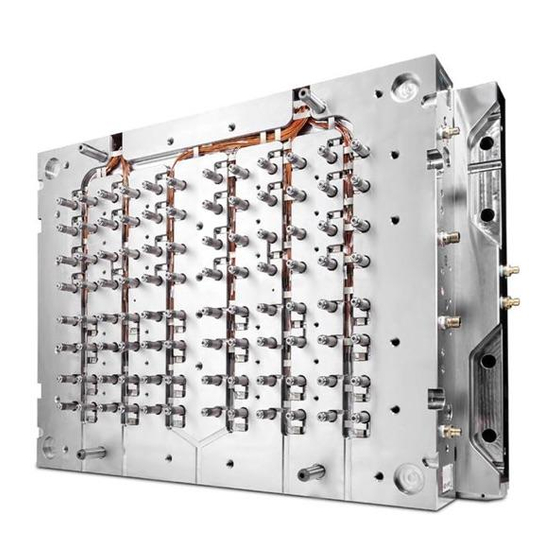
This section is a step-by-step guide to assembling your Mold-Masters Hot Runner system. 5.1 Cutaway of a Cast-in System This illustration of a typical Mold-Masters cast-in Hot Runner system is divided into two halves: valve side and non-valve side. The terminology Hot Half - Cast In Arrangement associated with the various components and features are listed below. -
Page 41: Cutaway Of A Bolt-In System
ASSEMBLY 5.2 Cutaway of a Bolt-in System This illustration of a typical Mold-Masters bolt-in Hot Runner system is divided into two halves: the valve side and the non-valve side. The terminology Hot Half - Bolt In Arrangement associated with the various components and features are listed below. -
Page 42: Cutaway Of A Mastershield System
The gate seals supplied with your system may need to be adjusted to tolerances based on the material grade and cooling in the cavity. Refer to your Mold-Masters General Assembly Gate Detail drawing to determine if gate seal finishing is required. Refer to the General Assembly drawing to determine which gating method applies. -
Page 43: Hot Valve / Hot Sprue / F Type
Contact Length “H” in mm (in.) Amorphous Filled or Reinforced 4.00 (0.16) Semi-crystalline Filled or Reinforced 3.00 (0.12) Crystalline Filled or Reinforced 2.00 (0.08) Figure 5-4 Hot valve / hot sprue gated system © 2020 Mold-Masters (2007) Limited. All Rights Reserved. Hot Runner User Manual... -
Page 44: Water-Cooled Gate Insert Installation (Optional)
4. Install O-rings onto the water-cooled gate insert. NOTE Align the dowel to ensure proper orientation. 1. O-rings 2. Dowel 3. Sealing bore Figure 5-5 Water-cooled gate insert Hot Runner User Manual © 2020 Mold-Masters (2007) Limited. All Rights Reserved. -
Page 45: Thermocouple Installation
Insert the thermocouple through the flange bore. 2. Manually bend the thermocouple tip against your thumb to approximately a 90° angle, ensuring bend length sufficient to reach the bottom of the thermocouple bore. © 2020 Mold-Masters (2007) Limited. All Rights Reserved. Hot Runner User Manual... - Page 46 Make sure that the terminal end of the thermocouple stays fully engaged in the slot. 5. Bend the thermocouple at the nozzle flange area. 6. Install the clip over the terminal end. Hot Runner User Manual © 2020 Mold-Masters (2007) Limited. All Rights Reserved.
-
Page 47: Thermocouple Removal For Non-Front Mounted Thermocouples
1. Remove the thermocouple from the electrical box and wire channels. 2. Remove the nozzle from the manifold plate. 3. Remove the thermocouple retaining clips. 4. Remove the thermocouple. © 2020 Mold-Masters (2007) Limited. All Rights Reserved. Hot Runner User Manual... -
Page 48: Dura Line Thermocouple Installation
5.9 Dura Line Thermocouple Installation This page only applies to Legacy Dura Nozzles. Mold-Masters Dura systems are supplied with an appropriate bending tool. Any questions regarding bending tools, please contact your Mold-Masters representative. Make sure that correct bending tool is used. Each different type of Dura nozzle requires a different bending tool. - Page 49 6. Press thermocouple downwards to sit against terminal end and secure to side of terminal end with heat resistant tape to ensure it does not become pinched between the nozzle and the manifold. © 2020 Mold-Masters (2007) Limited. All Rights Reserved. Hot Runner User Manual...
- Page 50 7. Use heat resistant tape to secure the nozzle wires and thermocouple wires just above or below the insulator pod. The nozzle is ready for assembly with the thermocouple fully installed. Hot Runner User Manual © 2020 Mold-Masters (2007) Limited. All Rights Reserved.
-
Page 51: Nozzle Insertion
NOTE Prior to commencing assembly verify manifold and nozzle cutouts in mold plates are to specification to ensure proper clearance to Hot Runner. Improper clearance will affect system performance. 5.10.1 Nozzle Insertion for Master-Series and Dura Lines 1. -
Page 52: Step Installation
4. Install the screws through the manifold and the step into the nozzle. 5. Torque screws to the value specified on the General assembly drawing. Manifold Step Screw Nozzle Figure 5-6 Step installation Hot Runner User Manual © 2020 Mold-Masters (2007) Limited. All Rights Reserved. -
Page 53: Nozzle Insertion-Thinpak Centi And Deci
2. Install the hardened washer. 3. Apply high temperature grease to the spring and install the disc spring with the correct orientation. THIS SIDE 4. Install the nozzle. © 2020 Mold-Masters (2007) Limited. All Rights Reserved. Hot Runner User Manual... - Page 54 Ensure the anti-rotation dowel is in the slot cutout in the manifold plate. Top view Anti- rotation dowel Side view 5. Check that the nozzle sits squarely in the nozzle well bore. Hot Runner User Manual © 2020 Mold-Masters (2007) Limited. All Rights Reserved.
-
Page 55: Nozzle Insertion-Mastershield Centi, Deci, And Pico
Figure 5-8 Master-Series Pico nozzle with optional MasterSHIELD components 1. Hardened washer 2. Disc spring 3. Nozzle retainer 4. Nozzle 1. Clean the seating bore of the nozzle well. 2. Install the bottom hardened washer. © 2020 Mold-Masters (2007) Limited. All Rights Reserved. Hot Runner User Manual... - Page 56 4. Install the disc spring in the correct orientation. 5. Install the top hardened washer. Install the nozzle retainer. 6. Install the nozzle. For anti-rotation, use the bolts between the manifold and nozzle. Hot Runner User Manual © 2020 Mold-Masters (2007) Limited. All Rights Reserved.
- Page 57 ASSEMBLY 5-18 7. Make sure that the nozzle sits correctly in the nozzle well bore. © 2020 Mold-Masters (2007) Limited. All Rights Reserved. Hot Runner User Manual...
-
Page 58: Nozzle Insertion-Mastershield Femto
3. Nozzle retainer 4. Nozzle 1. Clean the seating bore of the nozzle well. 2. Install the bottom hardened washer. 3. Apply high temperature grease to the first spring. Hot Runner User Manual © 2020 Mold-Masters (2007) Limited. All Rights Reserved. - Page 59 The bottom spring has a different orientation from that of other MasterSHIELD systems. 5. Install the top spring. NOTE The top spring has a different orientation to that of the bottom spring. © 2020 Mold-Masters (2007) Limited. All Rights Reserved. Hot Runner User Manual...
- Page 60 6. Install the top hardened washer. 7. Install the nozzle retainer. 8. Install the nozzle. For the anti-rotation version, use the bolts between the manifold and the nozzle. Hot Runner User Manual © 2020 Mold-Masters (2007) Limited. All Rights Reserved.
- Page 61 ASSEMBLY 5-22 9. Make sure that the nozzle sits correctly in the nozzle well bore. © 2020 Mold-Masters (2007) Limited. All Rights Reserved. Hot Runner User Manual...
-
Page 62: Nozzle Wire Layout
2. Wire retainer 3. Manifold 4. Manifold backing plate 5. Power wire 6. Mold plug 7. Electrical box 8. Manifold plate Figure 5-11 Thermocouple layout - side view Hot Runner User Manual © 2020 Mold-Masters (2007) Limited. All Rights Reserved. -
Page 63: Emergency Heater Sleeve
19 mm from the end closest to the nozzle flange. The following assembly instructions apply whether sleeve installation is done with the tool in the press or on the bench. Figure 5-12 Emergency heater sleeves © 2020 Mold-Masters (2007) Limited. All Rights Reserved. Hot Runner User Manual... - Page 64 Figure 5-13 Installed heater sleeve and tube assembly 2. Make sure that the nozzle is positioned within its cutout so that the heater element exit is aligned with the cutout in the plate. Hot Runner User Manual © 2020 Mold-Masters (2007) Limited. All Rights Reserved.
- Page 65 You may have to disassemble and re-assemble the nozzle. 4. Make sure that the emergency heater is aligned with the end of the chamfer on the nozzle body. © 2020 Mold-Masters (2007) Limited. All Rights Reserved. Hot Runner User Manual...
-
Page 66: Removal Of Emergency Heater Sleeve
2. Use the slots on the emergency heater sleeve to pull the emergency heater sleeve off the nozzle. See Figure 5-14. Figure 5-14 Slots on the emergency heater sleeve Hot Runner User Manual © 2020 Mold-Masters (2007) Limited. All Rights Reserved. -
Page 67: Valve Bushings
The valve bushing for Accu-Valve has a locating dowel pin with the mold. 2. Install the locating dowel. Ensure the dowel pin is not too long as this will effect the seal between the nozzle and the manifold. © 2020 Mold-Masters (2007) Limited. All Rights Reserved. Hot Runner User Manual... - Page 68 On bridge manifold systems, main to submanifold screws should be torqued 1/3 higher than specified on General Assembly drawing. 1. Mounting screw 2. Manifold 3. Valve bushing 4. Nozzle Figure 5-18 Valve bushing - screw installation Hot Runner User Manual © 2020 Mold-Masters (2007) Limited. All Rights Reserved.
-
Page 69: Mount The Manifold
2. Manifold locating dowel pin 3. Manifold and slot locator Manifold Locating Manifold Locator Figure 5-19 Manifold with a locator SURFACE A SURFACE B FACE Y Figure 5-20 Locator surface © 2020 Mold-Masters (2007) Limited. All Rights Reserved. Hot Runner User Manual... -
Page 70: Manifold Locator
3. If required, attach a crane of sufficient lifting capacity to the manifold. 4. Check for correct seating and height. 5. Check that there are no pinched wires. Hot Runner User Manual © 2020 Mold-Masters (2007) Limited. All Rights Reserved. -
Page 71: Manifold Locating Dowel Pin
Place the manifold on top of the nozzles and manifold locator. Slot Locator 4. Check for correct seating and height. 5. Check that there are no pinched wires. © 2020 Mold-Masters (2007) Limited. All Rights Reserved. Hot Runner User Manual... -
Page 72: Manifold Thermocouple Installation
10. Feed the wires back through the wire channel in the mold base to the electrical box. 90° 1. Thermocouple 2. Screw 3. Washer 4. Assembly Figure 5-22 Thermocouple installation Hot Runner User Manual © 2020 Mold-Masters (2007) Limited. All Rights Reserved. -
Page 73: Main Manifolds
4. Install the manifold locators. Refer to “Mounting the Manifold”. 5. Check that all components are free of debris. 1. Inlet seal 2. Submanifold Figure 5-24 Inlet seal without step © 2020 Mold-Masters (2007) Limited. All Rights Reserved. Hot Runner User Manual... -
Page 74: Inlet Seal Installation - With Step
These may or may not require grinding. For additional information please refer to “4.5 Establish Your System Type”. Hot Runner User Manual © 2020 Mold-Masters (2007) Limited. All Rights Reserved. -
Page 75: Pressure Disk: Final Grinding Required
Figure 5-27 Calculating nozzle bore depth “a” b) Measure the top section of the nozzle flange “b”. Figure 5-28 Calculating nozzle flange height “b” © 2020 Mold-Masters (2007) Limited. All Rights Reserved. Hot Runner User Manual... - Page 76 Material to be removed from each side of the pressure disk: 0.08 mm ÷ 2 = 0.04 mm (0.002 in.) Nozzle bores and pressure disks must be within tolerances specified in the General Assembly drawing. Hot Runner User Manual © 2020 Mold-Masters (2007) Limited. All Rights Reserved.
-
Page 77: Pressure Disk Installation
5. Measure the gap between the top of the manifold plate and the top of the pressure disk. Ensure that it matches the air gap value on the General Assembly drawing. © 2020 Mold-Masters (2007) Limited. All Rights Reserved. Hot Runner User Manual... -
Page 78: Ecodisk Installation
M5X0.8 screw EcoDisk Pressure disk Manifold A) Standard mount M5X0.8 screw EcoDisk Pressure disk Manifold B) Flush mount for retrofit or stack height limit Figure 5-31 EcoDisk mounting configurations Hot Runner User Manual © 2020 Mold-Masters (2007) Limited. All Rights Reserved. -
Page 79: Valve Disk - Final Grinding Required
5. Ensure correct air gap between the valve disk and the top plate as specified in the General Assembly drawing. 6. For information on removal, refer to “15.1 Valve Disk Removal” on page 15-1. © 2020 Mold-Masters (2007) Limited. All Rights Reserved. Hot Runner User Manual... - Page 80 5. Measure the gap between the top of the manifold plate and the top of the valve disk. Ensure that it matches the air gap value on the General Assembly drawing. Hot Runner User Manual © 2020 Mold-Masters (2007) Limited. All Rights Reserved.
-
Page 81: Support Bushing Installation For Systems With Mastershield
3. Use a dowel pin to install all of the support bushings into the manifold. See Figure 5-35. Support bushing Manifold plate Nozzle Figure 5-35 Support bushing in MasterSHIELD systems © 2020 Mold-Masters (2007) Limited. All Rights Reserved. Hot Runner User Manual... -
Page 82: Valve Disk Installation For Systems With Mastershield
For 2-piece valve disk - Insert valve stem into the manifold in appropriate orientation. Slide valve disk flange over the stem. For removal of valve disk stems, see “15.1 Valve Disk Removal” on page 15-1. Hot Runner User Manual © 2020 Mold-Masters (2007) Limited. All Rights Reserved. -
Page 83: Heater Plates Installation
Refer to the General Assembly drawing for the correct torques. NOTE Current bronze heater plates are directly interchangeable with previous copper or aluminum based plates that may exist on your Mold-Masters system. However, when multiple heater plates are controlled by one thermocouple, these heater plates must be made of the same material, be of equal wattage and be located in similar thermal environments. - Page 84 It is recommended that the heater plate wires be isolated and grouped so that they do not have to be disconnected if the manifold needs to be dismantled for repair. Hot Runner User Manual © 2020 Mold-Masters (2007) Limited. All Rights Reserved.
-
Page 85: Inlet Components Installation
1. Mounting screw 2. Nozzle radius 3. Back plate 4. Manifold 5. Bottom face Figure 5-39 Back plate installation © 2020 Mold-Masters (2007) Limited. All Rights Reserved. Hot Runner User Manual... -
Page 86: Center Heater Installation
Use anti-seize compound on screws. 7. Torque screws to values indicated on the General Assembly drawing. 1. Thermocouple 2. Center heater 3. Screw Figure 5-40 Center heater assembly Hot Runner User Manual © 2020 Mold-Masters (2007) Limited. All Rights Reserved. -
Page 87: Inlet Extension Installation
Feed the wires back through the wire channel in the mold base to the electrical box. 1. Screw 2. Center heater 3. Back plate 4. Manifold 5. Ground wire 6. Thermocouple 7. Cover plate 8. Set screw Figure 5-41 3-piece assembly © 2020 Mold-Masters (2007) Limited. All Rights Reserved. Hot Runner User Manual... -
Page 88: Inlet Extension With Pressure Sleeve
4. Place zone number on each wire and thermocouple. 5. Tape wires for each zone together. 6. Install the wires into the wire channels and secure with wire retainers. Hot Runner User Manual © 2020 Mold-Masters (2007) Limited. All Rights Reserved. - Page 89 8. For electrical checks, refer to “Section 6 - Electrical Testing”. 1. Inlet extension 2. Manifold 3. Extension tip 4. Pressure sleeve Figure 5-43 Inlet extension with sleeve © 2020 Mold-Masters (2007) Limited. All Rights Reserved. Hot Runner User Manual...
-
Page 90: Section 6 - Electrical Testing
Mold-Masters components and systems are either equipped with a protective earth conductor or there is a connector for this purpose. Before you carry out electrical work, make sure that the Hot Runner system is securely grounded. Turn the temperature control off and disconnect all electric wires coming from the mold. -
Page 91: Electrical Wiring Check
First, verify that the electrical equipment complies with its technical documentation. 6.3.2 Insulation Resistance Test Measure the insulation resistance between each pin of the Mold-Masters power connector, in particular the heating circuit and ground. The insulation resistance is measured at 500 V . -
Page 92: Verification Of Conditions For Protection By Automatic Disconnection Of Supply
Fault loop impedance verification and suitability of the associated overcurrent protective device. The power supply connections and incoming external grounding connections to the Hot Runner system must be verified by inspection (usually through a temperature control device). The conditions for protection by automatic disconnection of supply must be checked by both: •... -
Page 93: Thermocouple Continuity Test
Measure the resistance between each pair of heater power wires at the mold power connector. Compare your reading with your General Assembly drawing. Where: R = resistance V = voltage P = power © 2020 Mold-Masters (2007) Limited. All Rights Reserved. Hot Runner User Manual... -
Page 94: Ungrounded Thermocouple Continuity Test
1. Set up a multimeter to read Ohms resistance. 2. Connect one lead to the red thermocouple wire. 3. Connect the other lead to the mold plate that the hot runner system is installed in. 4. If you see an Ohms resistance, replace the thermocouple (faulty thermocouple). -
Page 96: Section 7 - Hot Half Assembly
Install the cavity plate before nozzle temperatures become more than 55°C (130°F) hotter than the cavity plate. Otherwise the nozzles will have expanded too much and may be damaged during insertion. Hot Runner User Manual © 2020 Mold-Masters (2007) Limited. All Rights Reserved. - Page 97 “Section 10 - Hydraulic / Pneumatic Actuators” on page 10-1. Check that the nozzle well depth (L) in the cavity plate is to Mold-Masters specifications. See Figure 7-1. 1. Attach a crane that is rated to support the weight of the cavity plate.
-
Page 98: Stack Mold Cavity Plate Installation
The assembly sequence will vary depending on the stack mold design. The following instructions should be considered as guidelines only. 1. Check that the nozzle well depth (L) in the cavity plate is to Mold-Masters specifications. See Figure 7-1. NOTE For valved systems, the Hot Half is provided with valve pins installed. - Page 99 13. Torque the mold mounting screws to required specifications. Refer to machine manufacturer’s documentation for torque values. 14. Connect wire lines, hydraulic, pneumatic and electrical components, as required. 15. Remove latches. 16. Set the mold opening sequence mechanism. © 2020 Mold-Masters (2007) Limited. All Rights Reserved. Hot Runner User Manual...
-
Page 100: Section 8 - System Startup And Shutdown
4. Connect all electrical components and monitor to ensure that all zones are receiving heat and all thermocouples are reacting appropriately. 5. If applicable, test the valve pin actuation, but only if the Hot Runner is at processing temperature. See CAUTION above. -
Page 101: Startup
Machine barrel is up to processing temperature. b) Mold cooling is on and at cooling temperature. 3. Heat up all Hot Runner manifolds and / or bridges and inlets (excluding the nozzles) to processing temperature. 4. Begin nozzle heating when the manifolds and / or bridges have come within 50°C of processing temperature. -
Page 102: Stack Mold Systems
3. Heat soak for 15 minutes. 4. Raise nozzle temperature to setpoint. 5. Heat soak for 20 minutes. 8.3 Shutdown The correct shutdown procedure for your Hot Runner system depends on the type of system: • Standard systems: see “8.3.1 Standard Hot Runner Systems” on page 8-4 •... -
Page 103: Standard Hot Runner Systems
1. Turn off all heat to the system. 2. Leave the mold cooling system turned on until the Hot Runner system temperature is within 55°C (130°F) of the mold temperature. 8.3.2 Stack Mold System... -
Page 104: Section 9 - Color Change
Purgings may appear solid but may still be hot and cause serious injury. 1. Empty hopper of existing color and clean thoroughly. 2. Increase Hot Runner system temperature on all zones 20°C (68°F) above processing temperatures. On Mold-Masters controllers, simply push the boost button on the controller to increase temperatures for a pre- determined time and temperature. -
Page 105: Procedure B: More Comprehensive
6. Run 10 - 15 shots with natural material. 7. Back off the injection unit and switch off all heat on the Hot Runner. 8. Allow the Hot Runner system to cool down. - Page 106 12. Turn on the Hot Runner system and heat to processing temperature. 13. Bring machine barrel back in. 14. Fill the Hot Runner with natural color resin to coat the melt channels with a neutral color (1-2 shots). 15. Introduce the new color.
-
Page 107: Section 10 - Hydraulic / Pneumatic Actuators
19. Valve pin 20. Piston rod wiper seal 21. Piston collar 5500 Series 6X00 Series 22. Dowel pin 7100 Series 8600 Series - AR Figure 10-1 Valve actuator components Hot Runner User Manual © 2020 Mold-Masters (2007) Limited. All Rights Reserved. -
Page 108: Pre-Installation
Figure 10-2 6X00 Series and 7100 Series bottom cylinder Figure 10-3 6X00 Series and 7100 Series bottom cylinder O-rings 1. Back-up ring 2. Inner Viton O-ring 3. Outer seal Figure 10-4 Seal kit PS0003 © 2020 Mold-Masters (2007) Limited. All Rights Reserved. Hot Runner User Manual... -
Page 109: Piston Assembly
Figure 10-5 Piston assembly 1. Piston bottom 2. Installation tool Figure 10-6 Piston bottom with installation tool 1. Outer seal 2. Installation tool Figure 10-7 Outer seal assembly Hot Runner User Manual © 2020 Mold-Masters (2007) Limited. All Rights Reserved. -
Page 110: Cylinder Top Assembly
2. Measure the distance AD and AC. NOTE Heat expansion difference to be removed from pin head. Figure 10-9 5500 Series - Measure distance © 2020 Mold-Masters (2007) Limited. All Rights Reserved. Hot Runner User Manual... - Page 111 3. Nozzle / angled valve pin 4. Nozzle well bore 5. Cavity Figure 10-10 Bushing for pin tip 40° 1. Land area 2. Cavity face Figure 10-11 Land location Hot Runner User Manual © 2020 Mold-Masters (2007) Limited. All Rights Reserved.
-
Page 112: 6X00 Series
1. Install the cylinder (where applicable) and piston bottom (without the pin and piston top) into the hydraulic plate. 7100 Series Figure 10-13 7100 Series - Measure distance 2. Measure the distance AC and BC. © 2020 Mold-Masters (2007) Limited. All Rights Reserved. Hot Runner User Manual... - Page 113 7. Assemble the hydraulic unit. 8. Heat the Hot Runner system to processing temperature. 9. Soak the pin in the Hot Runner system for 10 minutes to achieve the maximum heat expansion of the pin at the processing temperature. NOTE Mold cooling should be running.
-
Page 114: 8X00 Series
8. Assemble the hydraulic unit. 9. Heat the Hot Runner system to processing temperature. 10. Soak the pin in the Hot Runner system for 10 minutes to achieve the maximum heat expansion of the pin at the processing temperature. NOTE Mold cooling should be running. -
Page 115: 8600 - Ar Series
10. Lap the tip of the pin into the land area (steel section in the gate area) using a lapping guide bushing or valve bushing as a lapping guide. We recommend 400 - 600 grit lapping paste. 11. Assemble the hydraulic unit. Hot Runner User Manual © 2020 Mold-Masters (2007) Limited. All Rights Reserved. -
Page 116: Valve Pin Lapping Procedure For Tapered Valve Pins
The Viton O-rings used for the valve actuators are rated for operation below 200°C (400°F). Always turn ON the plate cooling prior to heating the Hot Runner system. Refer to the warning if O-rings have been subjected to higher than rated temperatures. -
Page 117: Valve Pin Finishing Of Head
Use appropriate protective clothing. Failure to do so can cause serious injury. 1. Heat the Hot Runner system to the processing temperature. 2. Allow the pin to soak in the Hot Runner system for 10 minutes to achieve the maximum heat expansion of the pin at processing temperature. NOTE Mold cooling should be running. -
Page 118: Valve Pin Assembly
6. Install piston top and tighten, recommended torque setting 20-27 Nm (15-20 ft-Ib). 1. Cylinder top 2. Valve pin 3. Spring retainer stud 4. Disk springs Figure 10-16 8 X 5 Disk spring assembly © 2020 Mold-Masters (2007) Limited. All Rights Reserved. Hot Runner User Manual... -
Page 119: Hydraulic Limit Switch Option (6500 Series And 6600 Series)
1. Sensor bracket assembly 2. Flat head screw 3. Trigger ring 4. O-ring 5. Limit switch cylinder top 6. Limit switch piston top 7. Cylinder Figure 10-17 Hydraulic limit switch components Hot Runner User Manual © 2020 Mold-Masters (2007) Limited. All Rights Reserved. -
Page 120: 7100 Series
5. Install piston top and tighten to recommended torque setting 20-27 Nm (15-20 ft-Ib). Figure 10-18 Cylinder installation 1. Actuator spacer 2. O-ring 3. Spacer threads up 4. Piston 5. Piston top Figure 10-19 Piston spacer installation © 2020 Mold-Masters (2007) Limited. All Rights Reserved. Hot Runner User Manual... -
Page 121: Install The Valve Actuator To The Hydraulic Plate
6. Press the valve pin into position, using a nylon mallet to finish seating the valve pin into the assembly. 7. Remove the installation tool. 8. Check that the cylinder top dowel and O-rings are installed. Hot Runner User Manual © 2020 Mold-Masters (2007) Limited. All Rights Reserved. - Page 122 5500 Series and 6X00 Series - continued 9. Install the cylinder top. IMPORTANT EXTOOLAS10 replaces EXTOOL5500A / EXTOOL6500A / EXTOOLAS01. 1. EXTOOLAS10 2. Cylinder extraction tool 3. Cylinder Figure 10-22 Cylinder extraction tool © 2020 Mold-Masters (2007) Limited. All Rights Reserved. Hot Runner User Manual...
-
Page 123: Hydraulic Limit Switch Option (6500 Series And 6600 Series)
10. Install the cylinder top. The piston top will protrude from the cylinder top. 11. Install the trigger ring on the head of piston top and lock its position with a flat head screw. Thread locking is recommended. (LOCTITE-243) Hot Runner User Manual © 2020 Mold-Masters (2007) Limited. All Rights Reserved. -
Page 124: Proximity Sensor Installation For Hydraulic Limit Switch Option
4. Repeat steps 1-3 to install the other bracket assembly into the cylinder top. 1. Socket head cap screw 2. Sheet metal sensor bracket 3. Proximity sensor with lock nuts Figure 10-23 Single sensor / bracket assembly © 2020 Mold-Masters (2007) Limited. All Rights Reserved. Hot Runner User Manual... -
Page 125: Cutout Options Based On Stroke
HYDRAULIC / PNEUMATIC ACTUATORS 10-19 10.11.1 Cutout Options Based on Stroke For 9.8 mm Stroke For 19.8 mm Stroke - Option 1 For 19.8 mm Stroke - Option 2 Hot Runner User Manual © 2020 Mold-Masters (2007) Limited. All Rights Reserved. -
Page 126: Test The Proximity Sensor For Hydraulic Limit Switch Option
If possible keep cooling on within Hot Half. Do not assemble new O-rings if the plates are still hot. Drain the oil before removing the pin from the hydraulics. © 2020 Mold-Masters (2007) Limited. All Rights Reserved. Hot Runner User Manual... -
Page 127: For Oil Systems
Failure to do so may result in degradation of material in the system. When heating the Hot Runner system for maintenance, mold cooling should be on to protect seals and O-rings. For systems with Accu-Valve EX, Accu-Valve MX or Accu-Valve CX gate seals: Gate seals must be removed prior to removing or re-installing valve pins. -
Page 128: Extraction Tools For Hydraulic And Pneumatic Actuators
M5 screws 14. Spacer 15. Nord lock M8.0 washer 16. Special socket head cap screw [M8X30M] 17. Puller base 18. Socket head cap screw [M6X20] 19. Adapter key © 2020 Mold-Masters (2007) Limited. All Rights Reserved. Hot Runner User Manual... - Page 129 VPAC0010/VPAC0011 HY680SA/HY680SAL EXTOOLAS10 EXTOOL680SAP PS0004TOOLx [MS11.04.035] [MS11.04.050] HY681SA/HY681SAL EXTOOL681SAP [MS11.04.035] HY8400x EXTOOLAS10 EXTOOL8400P1 PS0011TOOLx [MS11.04.030] [MS11.04.050] HY8500x HY8600xAR HY8800x PN6400x/PN6400xAR EXTOOLAS10 EXTOOL6400P [MS11.04.025] PN6410x/PN6410xAR PN6400SA EXTOOLAS10 EXTOOL6400SAP [MS11.04.040] Hot Runner User Manual © 2020 Mold-Masters (2007) Limited. All Rights Reserved.
-
Page 130: Section 11 - Slimstack Actuator
Refer to the General Assembly drawings for part names, sizes and quantities for any components. See “Figure 11-1 Slimstack actuator assembly” on page 11-2 for a full view of the assembly. Hot Runner User Manual © 2020 Mold-Masters (2007) Limited. All Rights Reserved. -
Page 131: Slimstack Actuator Assembly
27. Piston top 28. Piston bottom 29. Nozzle 30. Nozzle retainer 31. Disc springs 32. Custom supporting plate 33. Socket head cap screw Figure 11-1 Slimstack actuator assembly © 2020 Mold-Masters (2007) Limited. All Rights Reserved. Hot Runner User Manual... -
Page 132: Assembly Procedure
Outer body cap screw Piston bottom Valve pin Flat head Dowel Valve pin guide Inlet seal cap screw Set screw Pressure plug Valve pin holder Figure 11-2 Slimstack components Hot Runner User Manual © 2020 Mold-Masters (2007) Limited. All Rights Reserved. - Page 133 O-rings into the grooves using your finger. Ensure the O-rings are firmly seated in the groove. See Figure 11-3 and Figure 11-4. Figure 11-3 Install piston top O-rings Figure 11-4 Install piston bottom O-ring © 2020 Mold-Masters (2007) Limited. All Rights Reserved. Hot Runner User Manual...
- Page 134 4. Lock the ground wire using a set screw. See Figure 11-5. 1. Thermocouple 2. Ground wire 3. Set screw Figure 11-5 Install ground wire and thermocouple assemblies Hot Runner User Manual © 2020 Mold-Masters (2007) Limited. All Rights Reserved.
- Page 135 6. Insert the valve pin holder into the heated body slot and over the head of the valve pin. Valve pin head Valve pin holder Figure 11-7 Insert valve pin holder © 2020 Mold-Masters (2007) Limited. All Rights Reserved. Hot Runner User Manual...
- Page 136 8. Slide the valve pin holder to locate the valve pin head in the narrowed portion of the slot. See Figure 11-9. Narrowed portion Figure 11-9 Locate the valve pin head in the narrowed portion Hot Runner User Manual © 2020 Mold-Masters (2007) Limited. All Rights Reserved.
- Page 137 For step 10, the valve pin holder slot on the piston top must be facing downwards towards the nozzle. This slot is shown in Figure 11-11. Valve pin holder slot Figure 11-11 Slot for valve pin holder © 2020 Mold-Masters (2007) Limited. All Rights Reserved. Hot Runner User Manual...
- Page 138 See Figure 11-12 and Figure 11-13. Figure 11-12 Install piston assembly onto heated body Figure 11-13 Overhead view of seated piston assembly Hot Runner User Manual © 2020 Mold-Masters (2007) Limited. All Rights Reserved.
- Page 139 14. Insert the dowel pin into the valve bushing. See Figure 11-15. 1. Nozzle assembly 2. Valve bushing 3. SHCSM5X16 (2) 4. Dowel pin Figure 11-15 Install valve bushing © 2020 Mold-Masters (2007) Limited. All Rights Reserved. Hot Runner User Manual...
- Page 140 16. Position the dowel on the valve bushing to align with the slot on the heated body. Carefully attach the valve bushing unit to the heated body. See Figure 11-17. Figure 11-17 Attach valve bushing to the heated body Hot Runner User Manual © 2020 Mold-Masters (2007) Limited. All Rights Reserved.
- Page 141 Ensure the O-rings are firmly seated in the groove. See Figure 11-19. 19. Install the dowel pin onto the outer body. See Figure 11-19. 1. O-rings 2. Dowel pin Figure 11-19 Install O-rings and dowel pin © 2020 Mold-Masters (2007) Limited. All Rights Reserved. Hot Runner User Manual...
-
Page 142: Installation
2. Attach the locating ring to the outer body using flat head screws. Torque to 2.8 Nm (2 ft-lb). See Figure 11-21. Figure 11-21 Attach locating ring to outer body Hot Runner User Manual © 2020 Mold-Masters (2007) Limited. All Rights Reserved. - Page 143 See Figure 11-23. IMPORTANT Ensure that the nozzle and the heated body terminal end are correctly oriented before sliding the unit inside the manifold plate. Figure 11-23 Install Slimstack unit © 2020 Mold-Masters (2007) Limited. All Rights Reserved. Hot Runner User Manual...
- Page 144 6. Attach the custom support plate to the manifold plate with four socket head cap screws. Torque to 72 Nm (53 ft-lb). See Figure 11-25. Figure 11-25 Attach custom support plate Hot Runner User Manual © 2020 Mold-Masters (2007) Limited. All Rights Reserved.
- Page 145 Check all the connections and actuations. See Figure 11-27. Figure 11-27 Attach inlet seal to heated body 9. Install the remainder of the Hot Runner manifold system. See “Section 5 - Assembly” on page 5-1. © 2020 Mold-Masters (2007) Limited. All Rights Reserved.
-
Page 146: Section 12 - Sevg Plus Actuator
The SeVG Plus is an industrial grade actuator intended to perform the functions of moving the working mechanisms and providing the necessary force and speed for a given control cycle when installed in a Hot Runner system. 12.2 SeVG Plus Actuator Models... -
Page 147: Sevg Plus Model Options
5. Motor locating spigot 2. Valve pin holder (bottom) 6. Motor mount flange 3. Valve pin holder (top) 7. SHCSM6X25 4. Motor rod 8. Motor Figure 12-1 SE40-20 actuator © 2020 Mold-Masters (2007) Limited. All Rights Reserved. Hot Runner User Manual... -
Page 148: Se40-20C Actuator - Cooled
IMPORTANT Mold-Masters assumes no responsibility for connection, monitoring and / or maintenance of any cooling system associated with an SeVG Plus system. 6. Motor mount flange 1. -
Page 149: Se20-15 Actuator - Non Cooled
5. Motor locating flange 1. Valve pin 6. Motor 2. Valve pin holder (bottom) 7. SHCSM5X155 3. Valve pin holder (top) 4. Motor locating spigot Figure 12-3 SE20-15 actuator © 2020 Mold-Masters (2007) Limited. All Rights Reserved. Hot Runner User Manual... -
Page 150: Sevg Plus In Plate Mounted Systems
2. Frame plate 3. Actuator plate 4. Manifold plate Note: non cooled model shown Figure 12-4 SE40-20 actuator in a Hot Runner system 12.6.1 SE20-15 Model 1. SeVG Plus actuator 2. Frame plate 3. Actuator plate 4. Manifold plate... -
Page 151: Assembly And Installation
A template for the appropriate hole pattern is provided in Figure 12-6. Front view Rear view Bulkhead connectors Hole pattern template Figure 12-6 Bulkhead connectors and template © 2020 Mold-Masters (2007) Limited. All Rights Reserved. Hot Runner User Manual... -
Page 152: Attach The Water Lines (Cooled Models Only)
Figure 12-7 Motor rod flats IMPORTANT If the Hot Runner system contains plastic, heat the system to processing temperature before the assembly is placed and see “Warning - hot surfaces” on page 12-6. Make sure that the cooling system is also connected. -
Page 153: Assemble And Install The Valve Pin Holder
[6 to 7 ft-lbs]. See Figure 12-4. 1. Motor rod 2. Valve pin holder (top) 3. Valve pin holder (bottom) 4. Valve pin Figure 12-4 Valve pin holder components © 2020 Mold-Masters (2007) Limited. All Rights Reserved. Hot Runner User Manual... - Page 154 Attach to the actuator plate with four SHCSM6X25 screws. Torque to 18 Nm [13 ft-lbs].See Figure 12-5 and Figure 12-6. Figure 12-5 Install the SE40-20 actuator Figure 12-6 Install the 40-20C actuator Hot Runner User Manual © 2020 Mold-Masters (2007) Limited. All Rights Reserved.
- Page 155 See Figure 12-8. Figure 12-7 Install the SE20-15 actuator × Figure 12-8 Use the correct screws © 2020 Mold-Masters (2007) Limited. All Rights Reserved. Hot Runner User Manual...
-
Page 156: Disassembly
3. Remove the four SHCSM6X25 mounting screws. See Figure 12-9. Figure 12-9 Remove the four mounting screws 4. Pull motor up until the valve pin is free to disengage. Hot Runner User Manual © 2020 Mold-Masters (2007) Limited. All Rights Reserved. -
Page 157: Se20-15 Model
3. Remove the two SHCSM5X155 mounting screws. See Figure 12-10. Figure 12-10 Remove the two mounting screws 4. Pull motor up until the valve pin is free to disengage. © 2020 Mold-Masters (2007) Limited. All Rights Reserved. Hot Runner User Manual... -
Page 158: Section 13 - E-Drive
7. Top plate 8. Fixed idler 9. Drive pulley 10. Idler pulley 11. Timing belt 12. Ball-screw pulley 13. Tensioning idler pulley 14. Tensioning idler screw Figure 13-1 E-Drive system Hot Runner User Manual © 2020 Mold-Masters (2007) Limited. All Rights Reserved. - Page 159 Typical E-Drive System - continued 1. Synchro-plate 2. Inlet extension 3. Tensioning idler assembly 4. Ball-screw assembly 5. Synchro-plate 6. Valve pin holder 7. Valve pin Figure 13-2 E-Drive system (continued) © 2020 Mold-Masters (2007) Limited. All Rights Reserved. Hot Runner User Manual...
-
Page 160: E-Drive Components
E-DRIVE 13-3 13.1.1 E-Drive Components E-Drive motor mount - exploded view Fix idler Ball-screw assembly Tensioning idler assembly Figure 13-3 E-Drive components Hot Runner User Manual © 2020 Mold-Masters (2007) Limited. All Rights Reserved. -
Page 161: E-Drive Safety
Mold-Masters for clarification. E-Drive components are rated to operate at temperatures less than 40 ºC (104ºF). Do not heat the Hot Runner system without connecting a proper cooling system. In addition, if your application mold temperature needs to be set above 40 ºC (104 ºF). -
Page 162: Assembly
WARNING Review “Section 3 - Safety” on page 3-1 before performing any assembly procedures. The Mold-Masters E-Drive system is shipped pre-assembled and requires minimal pre-installation assembly. The following details the assembly / installation procedures for various components of the E-Drive. -
Page 163: Assembly Detail
E-DRIVE 13-6 13.3 Assembly Detail 13.3.1 Hot Runner Assembly 1. Assemble the Hot Runner system to the manifold plate. 13.3.2 Interface Plate Assembly 1. Assemble the interface plate to the manifold plate. Install the fastening screws between the plates. © 2020 Mold-Masters (2007) Limited. All Rights Reserved. -
Page 164: Synchro-Plate Assembly
2. Ball-nut flange seating area 3. Guide bushings with top / bottom retainers 4. Bottom stop buttons 2. Assemble the valve pin holders into the synchro-plate. Valve pin holders Hot Runner User Manual © 2020 Mold-Masters (2007) Limited. All Rights Reserved. -
Page 165: Ball-Screw Preparation
3. Move the ball-screw to the other end (position 02) of the spindle and bring it back to the position 01. 4. Take precautions to keep it away from the dirt. © 2020 Mold-Masters (2007) Limited. All Rights Reserved. Hot Runner User Manual... -
Page 166: Ball-Screw Assembly
2. Install the cover plate into position. 3. Assemble ball-nut on ball-screw with a torque of 43-45 Nm (31.7 to 33.1 lbf-ft). NOTE Ball-screw mounting kit EDRIVEBSMNTKITP is supplied with the system. Hot Runner User Manual © 2020 Mold-Masters (2007) Limited. All Rights Reserved. -
Page 167: Ball-Screw Maintenance
If your mold is not used for a long time, inspect the ball-screws for oxidation and dirt. Clean and lubricate the ball-screws before you start the machine. We recommend to call a Mold-Masters service technician for the inspection. Regular Maintenance Recommendation: Maintenance by cycle: Every 1.6 million cycles. - Page 168 Check the tension and span vibration frequency values in the meter. If required, adjust the tensioning idler screw and make sure that the tension in the belt is 300 N (67 lbf). 5. Tighten the tensioning idler screws. Hot Runner User Manual © 2020 Mold-Masters (2007) Limited. All Rights Reserved.
-
Page 169: Inspect Parallelism Of The Synchro-Plate
Enlarged view Measuring holes 2. Once the parallelism is confirmed, tighten the screws (2 Nos) in each ball- screw pulley. Screws 13.3.12 Assemble the Insulation Plate and Locating Ring © 2020 Mold-Masters (2007) Limited. All Rights Reserved. Hot Runner User Manual... -
Page 170: Perform E-Drive Controller Checks
3. Idler tensioning screw 4. Taper bushing screws 5. Use standard 1/4 - 20 socket head cap screw to jack taper lock Figure 13-5 Installation or replacement of the belt Hot Runner User Manual © 2020 Mold-Masters (2007) Limited. All Rights Reserved. - Page 171 15. If possible, while system is heated, do a few dry cycles (using 24 V manual trigger) and check movement and noise. Double check the position of belt within all pulleys. See E-Drive Controller Operating Manual. © 2020 Mold-Masters (2007) Limited. All Rights Reserved. Hot Runner User Manual...
-
Page 172: Check For Misalignment
Parallel misalignment fleeting angle driveR driveN Angular misalignment fleeting angle driveR driveN Figure 13-6 Misalignment check Hot Runner User Manual © 2020 Mold-Masters (2007) Limited. All Rights Reserved. -
Page 173: Section 14 - Mag-Pin Option
Valve pin size: 2.5 and 3 mm (0.1 and 0.12 in.) diameter valve pins • Gate style NOTE Please contact Mold-Masters to understand if the Mag-Pin option is applicable to your product. Hot Runner User Manual © 2020 Mold-Masters (2007) Limited. All Rights Reserved. -
Page 174: Mag-Pin Assembly (3D View)
Do not keep any tools or metal objects in the magnetic field area. Failure to follow the instructions can cause injury to personnel and / or damage to the parts. Figure 14-2 Mag-Pin safety hazards © 2020 Mold-Masters (2007) Limited. All Rights Reserved. Hot Runner User Manual... -
Page 175: Mag-Pin Operation
The valve pin separates from the synchro-plate at the magnet interface. Open position Open position (Activated gate-10mm stroke shown) (Deactivated gate-10mm stroke shown) Closed position (Both activated and deactivated conditions) Figure 14-3 Mag-Pin activation / deactivation Hot Runner User Manual © 2020 Mold-Masters (2007) Limited. All Rights Reserved. - Page 176 Closed Position Open Position Deactivated gate Activated gate Figure 6-3 Mag-Pin activation / deactivation (continued) © 2020 Mold-Masters (2007) Limited. All Rights Reserved. Hot Runner User Manual...
-
Page 177: Handling Magnets
Make sure that you keep the groups of magnets in a thick plastic container to avoid impact with other parts or tools. 1. Plastic spacer 2. Magnet Hot Runner User Manual © 2020 Mold-Masters (2007) Limited. All Rights Reserved. -
Page 178: Assembly Summary
Do not place the magnets close to any ferromagnetic parts or other magnets. Their light weight and magnetic strength can cause the magnets to collide which will damage the magnet faces. © 2020 Mold-Masters (2007) Limited. All Rights Reserved. Hot Runner User Manual... -
Page 179: Place The Magnet On Top Of Magnet Retainer
14.6.3 Clean the Magnet Holder 1. Clean and inspect the magnet holder. 2. Make sure that the interface with the magnet is free from grease, burrs or dust. Hot Runner User Manual © 2020 Mold-Masters (2007) Limited. All Rights Reserved. -
Page 180: Assemble The Magnetic Retainer To Magnet Holder
1. Install the magnet holder and magnet into the housing. 2. Use a 5 mm (0.2 in.) hex key and rotate the magnet holder in a counter- clockwise direction until the threaded part protrudes. © 2020 Mold-Masters (2007) Limited. All Rights Reserved. Hot Runner User Manual... -
Page 181: Assemble The Nut And Lock Magnet Holder
1. Insert the valve pin into the valve pin retainer. 2. Hold the valve pin holder with your hand. 3. Use a wrench and assemble the valve pin retainer with valve pin into the valve pin holder. Hot Runner User Manual © 2020 Mold-Masters (2007) Limited. All Rights Reserved. -
Page 182: O-Ring Installation Into Valve Pin Holder
14.6.9 Assemble Valve Pin into Housing Assembly 1. Carefully assemble the valve pin into the housing assembly. 2. Make sure that there are no impact forces on the magnet. © 2020 Mold-Masters (2007) Limited. All Rights Reserved. Hot Runner User Manual... -
Page 183: Install Mag-Pin Assembly Into The Synchro-Plate
1. Heat the system and adjust the valve pin height if the valve pin protrusion is not correct. 2. The Mag-Pin assembly at this condition can be installed into the synchro- plate Hot Runner User Manual © 2020 Mold-Masters (2007) Limited. All Rights Reserved. -
Page 184: Mag-Pin Extraction
MAG-PIN OPTION 14-12 14.7 Mag-Pin Extraction NOTE For the Mag-Pin extraction Mold-Masters recommends to use the extraction tool Mold-Masters part # EXTOOL13 (see below) with extraction tool Mold-Masters part # EXTOOLAS10. 1. EXTOOL13B 2. EXTOOL13A 3. M8 thread 4. M5 thread 1. - Page 185 Place the extraction tool EXTOOL13A on top of the valve pin holder. b) Couple the extraction tool with the M8 screw and M8 washer and extract the Mag-Pin assembly. 1. M8 screw 2. EXTOOL13A 3. M6 screw Hot Runner User Manual © 2020 Mold-Masters (2007) Limited. All Rights Reserved.
- Page 186 Method 1: Extract the valve pin and holder with a M5 screw or other adaptor with a M5 thread in front. M5 screw © 2020 Mold-Masters (2007) Limited. All Rights Reserved. Hot Runner User Manual...
- Page 187 Method 2: Extract the valve pin and holder using extraction tool EXTOOLAS10 with extraction tool EXTOOL13B. Use the M5 thread end for extraction of valve pin. 1. M8 thread 2. EXTOOL13B 3. M5 thread Hot Runner User Manual © 2020 Mold-Masters (2007) Limited. All Rights Reserved.
-
Page 188: Section 15 - Maintenance
Hot Runner system. This chapter is a guide to maintaining selective components. Repairs that should be performed by Mold-Masters personnel are not included. If you need an item repaired that is not included in this section, please call Mold- Masters support. -
Page 189: Extraction Of 1-Piece Valve Disk
Ensure that the pulling direction is perpendicular to the manifold surface. 1. EXTOOLAS10 2. Valve disk extraction tool 3. Valve disk (1-piece) Figure 15-2 1-piece valve disk extraction - method 1 © 2020 Mold-Masters (2007) Limited. All Rights Reserved. Hot Runner User Manual... - Page 190 Ensure that the pulling direction is perpendicular to the manifold surface. 1. EXTOOLAS10 2. LHCSM4X16 (2x) 3. Spacer 4. Valve disk extraction tool 5. Valve disk (1-piece) Figure 15-3 1-piece valve disk extraction - method 2 Hot Runner User Manual © 2020 Mold-Masters (2007) Limited. All Rights Reserved.
-
Page 191: Extraction Of 2-Piece Valve Disk
See Figure 15-5. 1. EXTOOLAS10 2. LHCSM4X16 (2x) 3. Spacer 4. Extraction tool for continuous groove models 5. Valve disk stem Figure 15-5 For valve disks with continuous grooves © 2020 Mold-Masters (2007) Limited. All Rights Reserved. Hot Runner User Manual... - Page 192 For close pitch conditions, use EXTOOLAS10 with a spacer. 5. Extract the valve disk from the manifold. IMPORTANT Ensure that the pulling direction is perpendicular to the manifold surface. Hot Runner User Manual © 2020 Mold-Masters (2007) Limited. All Rights Reserved.
-
Page 193: Valve Disk Extraction Tool Overview
Style with thread M7-1.0 2-piece Extended Inverted EXTOOL42 Style with thread M10-1.5 2-piece Extended Inverted EXTOOL43 Style with thread M15-1.5 1. Flange 2. Stem * Discontinued. Spare parts available. © 2020 Mold-Masters (2007) Limited. All Rights Reserved. Hot Runner User Manual... - Page 194 Ø39 mm Valve Disks EXTOOL29 Non-Inverted Design Ø42 mm Valve Disks EXTOOL30 Non-Inverted Design Ø49 mm Valve Disks EXTOOL31 Non-Inverted Design 1. Flange 2. Stem * Discontinued. Spare parts available. Hot Runner User Manual © 2020 Mold-Masters (2007) Limited. All Rights Reserved.
-
Page 195: Terminal End Removal And Installation
Please contact Mold-Masters Spare Parts Department to ensure you have the correct repair kit and crimping tool. The tools, along with the lead wire replacement kit, are available through the Mold-Masters Spare Parts Department. © 2020 Mold-Masters (2007) Limited. All Rights Reserved. -
Page 196: Terminal Assembly
2. Ensure the terminal end is clean. 3. Slide the element sleeve, silicon seal and ceramic insulator onto the wires. 4. Slide crimps onto leads. Stranded wire should extend beyond the crimp. Hot Runner User Manual © 2020 Mold-Masters (2007) Limited. All Rights Reserved. - Page 197 7. Slide the ceramic insulator and silicon seal into place. 8. Screw the element sleeve into the position. Make sure that the silicon sleeve does not rotate with the sleeve which may damage the wire. © 2020 Mold-Masters (2007) Limited. All Rights Reserved. Hot Runner User Manual...
-
Page 198: Heater Plate Power Lead Removal
2. Slide ceramic sleeve off. 3. Remove the power leads using crimp removal tool. 1. Power leads 2. Set screws 3. Ceramic sleeve 4. Heater plate Figure 15-7 Terminal end assembly Hot Runner User Manual © 2020 Mold-Masters (2007) Limited. All Rights Reserved. -
Page 199: Installation
NOTE Use the socket supplied in the Mold-Masters tool kit to loosen the gate seal. It is recommended to use a temperature controller for this procedure. If a temperature controller is not available, contact your nearest Mold-Masters Service Department. -
Page 200: Gate Seal Removal
It is recommended the nozzle be removed from the system before removing the gate seal. Use the socket supplied in the Mold-Masters tool kit to loosen the gate seal. The following procedure applies to all gate seals (including carbide) with threads larger than an M6 (excluding TIT Edge). -
Page 201: Gate Seal Replacement
1. Clean the nozzle, especially the thread and runner. 2. Clean all residual plastic from the threads and counter bore of the gate seal. Figure 15-8 (A) Cleaning location © 2020 Mold-Masters (2007) Limited. All Rights Reserved. Hot Runner User Manual... - Page 202 7. Torque the gate seal to the appropriate value. Refer to “Torque Settings” on page 15-24. 8. Check that the seal has bottomed out, heat nozzle to process temperature and re-torque seal. Hot Runner User Manual © 2020 Mold-Masters (2007) Limited. All Rights Reserved.
-
Page 203: Sprint Gate Seal Maintenance
15.6.1 Sprint Nozzle Tip Removal CAUTION The Hot Runner system must be turned off and cooled to below CAUTION 38 ºC (100 ºF) before cavity plate is removed. The cavity plate can then be removed to expose the nozzle tips. -
Page 204: Sprint Nozzle Tip Installation
4. After ensuring good contact, clean die spotting blue compound off of both surfaces. 5. Apply nickel based anti-seize compound to the gate seal threads ONLY. Hot Runner User Manual © 2020 Mold-Masters (2007) Limited. All Rights Reserved. -
Page 205: Clean Nozzle Insulator Cap
1. Heat cap with heat gun. 2. Remove molten plastic and wipe remainder from insulator cap. 15.8 Installing Nozzle Insulator Cap 1. Press fit insulator cap onto torpedo by hand. © 2020 Mold-Masters (2007) Limited. All Rights Reserved. Hot Runner User Manual... -
Page 206: Valve Actuator Maintenance
3. Zero indicator to spacer blocks. 4. Move indicator to correct reference point on nozzle tip (per drawing). 5. Check that nozzle height is within drawing specification. 6. Repeat for each nozzle. Hot Runner User Manual © 2020 Mold-Masters (2007) Limited. All Rights Reserved. -
Page 207: Latches
For additional instructions on latching in the machine refer to the machine manufacturers manual. 1. Open the mold. 2. Ensure that the machine and Hot Runner controller has been locked out and tagged out. 3. Apply lockout / tagout to the machine power source and Hot Runner controller. - Page 208 12. Apply lockout / tagged out. Refer to machine manufacturer’s documentation for procedures. 13. Remove the latches. 14. Latch the cavity plate to the core plate or Cold Half. 15. Remove lockout / tagged out. Hot Runner User Manual © 2020 Mold-Masters (2007) Limited. All Rights Reserved.
-
Page 209: Latch The Cavity Plate To The Manifold Plate (Hot Half)
CAUTION The nozzles must be within 55°C (130°F) of mold temperature to prevent damage to Hot Runner and mold components. For cylindrical valve gated systems, valve pins should be in the open position prior to removal of the cavity plate to prevent damage. - Page 210 12. Install and torque the cavity plate mounting screws. Torque to required specifications. Refer to assembly drawings for required torque settings. 13. Install hoses if required. 14. Remove latches from both sides of the mold. Hot Runner User Manual © 2020 Mold-Masters (2007) Limited. All Rights Reserved.
-
Page 211: Torque Settings
15.14.3 Torque Settings of Summit-Series Gate Seals Table 15-6 Torque Settings of Summit-Series Gate Seals Product Line Product Size Torque [ft-lb] Torque [N·m] Summit Series Femto Pico 12-13 16-18 Centi 20-22 27-30 © 2020 Mold-Masters (2007) Limited. All Rights Reserved. Hot Runner User Manual... -
Page 212: Torque Settings Of Dura Gate Seals
15.14.5 Torque Settings of ThinPAK Gate Seals Table 15-8 Torque Settings of ThinPAK Gate Seals Product Line Product Size Torque [ft-lb] Torque [N·m] ThinPAK Centi 27-29 37-39 Deci 34-36 46-49 Hot Runner User Manual © 2020 Mold-Masters (2007) Limited. All Rights Reserved. -
Page 213: System And Plate Screw Torques
Tighten the screws to the specified torque in a minimum of two steps. Quality and length of screws must be as specified on Mold-Masters General Assembly drawings. Table 15-9 Torque Chart for System Assembly Screws... -
Page 214: Section 16 - Tit Edge Gated System
Refer to gate detail on the General Assembly drawing. Heat expansion of the nozzle must also be considered. Figure 16-1 TIT Edge gated system Figure 16-2 TIT Edge gate seal Hot Runner User Manual © 2020 Mold-Masters (2007) Limited. All Rights Reserved. -
Page 215: Tit Edge Gate Seals
16.2.1 Remove the Gate Seal NOTE If the cavity plate is easily removed you can access the nozzle seals while still in the system. Hot Runner systems must be cold before the cavity plate can be removed. 1. Apply penetrating oil to the threads. -
Page 216: Section 17 - Accu-Line
15. Valve pin 16. Dowel pin 17. Socket head cap screw ™ 18. Accu-Line bushing 19. Nozzle 20. Liner 21. Gate seal Figure 17-1 Centi Accu-Line™ body assembly Hot Runner User Manual © 2020 Mold-Masters (2007) Limited. All Rights Reserved. -
Page 217: Accu-Line™ With Valve Bushing
1. Check components against the parts list. 2. Put cylinder backup washer and O-ring into cylinder body groove. Bend the cylinder hard ring into a kidney shape and insert into position in cylinder body. © 2020 Mold-Masters (2007) Limited. All Rights Reserved. Hot Runner User Manual... - Page 218 O-ring and the inner side of the hard ring to help assembly. 7. Apply a small amount of lubrication to all outside faces of seals prior to step 8 to help assembly. Hot Runner User Manual © 2020 Mold-Masters (2007) Limited. All Rights Reserved.
- Page 219 10. Make sure installed seals engage into guiding chamfer. Press piston smoothly and gently, applying even force. 11. Insert O-ring into cylinder top and assemble it to cylinder body. © 2020 Mold-Masters (2007) Limited. All Rights Reserved. Hot Runner User Manual...
- Page 220 14. Attach gate seal and liner to nozzle. Tighten to specifications detailed in the General Assembly drawings. Attach nozzle thermocouple. 15. Attach valve bushing. Tighten to specifications detailed in the General Assembly drawing. Hot Runner User Manual © 2020 Mold-Masters (2007) Limited. All Rights Reserved.
- Page 221 General Assembly drawing. Thermocouple installed in groove Heater body wire retainer 20. Slide the valve pin holder into the heater body slot and over the valve pin head. © 2020 Mold-Masters (2007) Limited. All Rights Reserved. Hot Runner User Manual...
- Page 222 21. Carefully place the nozzle assembly into the hydraulic unit as shown. 22. Ensure that the nozzle terminal end is correctly oriented. 23. Secure the valve pin holder to piston. Tighten to specifications detailed in the General Assembly drawing. Hot Runner User Manual © 2020 Mold-Masters (2007) Limited. All Rights Reserved.
- Page 223 ACCU-LINE™ 17-8 Accu-Line™ with Valve Bushing Assembly - continued 24. Assemble inside mold and verify assembly and all connections for accuracy. © 2020 Mold-Masters (2007) Limited. All Rights Reserved. Hot Runner User Manual...
-
Page 224: Accu-Line™ With Valve Insert
32. O-ring 33. Cooling plug 34. Socket head cap screw 35. Insulation plate 36. Support sleeve 37. Cover plate 38. Socket head cap screw Figure 17-3 Accu-Line™ body assembly Hot Runner User Manual © 2020 Mold-Masters (2007) Limited. All Rights Reserved. -
Page 225: Pre-Assembly Of Accu-Line™ With Valve Insert
1. Make sure that the length of your valve pin is the same as that of the General Assembly drawing. 2. Make sure that your components match those of the parts list: © 2020 Mold-Masters (2007) Limited. All Rights Reserved. Hot Runner User Manual... -
Page 226: Assembly Of Accu-Line™ With Valve Insert
2. Use your fingers to gently push the rod seal and guide ring into the grooves in the cylinder. Make sure that both sit firmly in the grooves. 22.Guide ring 23.Rod seal Hot Runner User Manual © 2020 Mold-Masters (2007) Limited. All Rights Reserved. - Page 227 In / out cooling lines within the plate 5. Apply grease to the guide ring, piston seal, and rod seal assembly grooves in the outer surface of the piston. © 2020 Mold-Masters (2007) Limited. All Rights Reserved. Hot Runner User Manual...
- Page 228 Make sure that they sit firmly in the grooves. 29. Guide ring 30. Rod seal 26. Piston seal 27. Guide ring Hot Runner User Manual © 2020 Mold-Masters (2007) Limited. All Rights Reserved.
- Page 229 CAUTION CAUTION The hole shown in the following figure has a chamfer. Be careful to avoid damaging the piston seal when inserting the piston assembly. © 2020 Mold-Masters (2007) Limited. All Rights Reserved. Hot Runner User Manual...
- Page 230 11. Use your fingers to gently push the O-ring into the outer groove of the cylinder top. Make sure that the O-ring sits firmly in the groove. Hot Runner User Manual © 2020 Mold-Masters (2007) Limited. All Rights Reserved.
- Page 231 15. Insert the actuator connection hose fittings into the supply ports on the bottom of the unit assembly. 1. Cooling in 2. Cooling out 3. Gate open 4. Gate close © 2020 Mold-Masters (2007) Limited. All Rights Reserved. Hot Runner User Manual...
- Page 232 Insert the end of the thermocouple fully into the mating hole and bend it into the thermocouple groove. 1. Termcon assembly 2. Ground wire assembly 3. Thermocouple assembly Hot Runner User Manual © 2020 Mold-Masters (2007) Limited. All Rights Reserved.
- Page 233 19. Install the inlet tip in the heated body, and tighten to a torque of 61 N∙m (45 lbf-ft). 20. Attach the gate seal and liner to the nozzle. 21. Attach the nozzle thermocouple. © 2020 Mold-Masters (2007) Limited. All Rights Reserved. Hot Runner User Manual...
- Page 234 Insert the screws, and tighten them to a torque of 14 N∙m (10 lbf-ft). 25. Slide the valve pin holder into the heated body slot and over the valve pin head. Hot Runner User Manual © 2020 Mold-Masters (2007) Limited. All Rights Reserved.
- Page 235 The air gap is determined by the flange depth of the mold plate. 27. Carefully place the nozzle assembly into the hydraulic unit. Make sure that the nozzle terminal end is correctly oriented. © 2020 Mold-Masters (2007) Limited. All Rights Reserved. Hot Runner User Manual...
- Page 236 28. Attach the valve pin holder to the piston using shoulder head screws, and tighten them to a torque of 3 N∙m (2.2 lbf-ft). 29. Install the unit in the mold. Examine all the connections and actuations. Hot Runner User Manual © 2020 Mold-Masters (2007) Limited. All Rights Reserved.
-
Page 237: Section 18 - Melt-Disk System
If your system has a Reverse Melt Link, you will need to follow the Reverse Melt Link startup and shutdown procedures. See Sections 18.8.2 and 18.9.2 for more information. Hot Runner User Manual © 2020 Mold-Masters (2007) Limited. All Rights Reserved. -
Page 238: System With Cast-In Heater Element
4. Torpedo tip 5. Melt-Disk locator 6. Melt-Disk 7. Melt transfer link 8. Transfer seal 9. Torpedo tip 10. Melt-Disk locator Figure 18-2 Melt-Disk system with cast-in heater element © 2020 Mold-Masters (2007) Limited. All Rights Reserved. Hot Runner User Manual... -
Page 239: Melt-Disk Preparation / Cleaning
4. Apply anti-seize compound to the threads of the gate seals, using Mold- Masters supplied compound. 5. Insert the pointed end of the tips (torpedoes) into the threaded end of the gate seal. Hot Runner User Manual © 2020 Mold-Masters (2007) Limited. All Rights Reserved. - Page 240 Thread size Imperial Metric 10 - 11 ft-lb 14 - 15 Nm 7. Torque gate seals in heated condition at processing temperature as specified in the General Assembly drawing. © 2020 Mold-Masters (2007) Limited. All Rights Reserved. Hot Runner User Manual...
-
Page 241: Nozzle Thermocouple Assembly
1. Remove the thermocouple retaining screw from the Melt-Disk. 2. Insert the thermocouple tip into the thermocouple hole until it touches the bottom of the hole. 3. Bend the thermocouple 90° towards the terminal. Hot Runner User Manual © 2020 Mold-Masters (2007) Limited. All Rights Reserved. - Page 242 4. Attach the thermocouple with the thermocouple retaining screw. 5. Use heat resistant tape just above the insulator pod to attach the nozzle wires and thermocouple wires together. 6. Set the thermocouple assembly aside. © 2020 Mold-Masters (2007) Limited. All Rights Reserved. Hot Runner User Manual...
-
Page 243: Optional Quick Disconnect Terminal Ends
Wire Stop 7. Wire stop slot Slot (In Contact) (in contact) Wire Stop 8. Wire stop Wire Size Markings 9. Wire size markings Figure 18-5 QDISC - CRIMP tool Hot Runner User Manual © 2020 Mold-Masters (2007) Limited. All Rights Reserved. -
Page 244: Crimp The Quick Disconnects
18.6.2 Assemble the System with Quick Disconnects 1. When assembling the system, connect female and male connector pins. 2. Then screw male sleeve into female sleeve. © 2020 Mold-Masters (2007) Limited. All Rights Reserved. Hot Runner User Manual... -
Page 245: Assembly Of Melt Disk To The Nozzle
5. Ensure the sharp edge of the Melt-Link does not get damaged when pushing the two halves together. MTL014A threaded into nozzle MTL014B threaded into Melt-Disk Do not damage sharp edge Hot Runner User Manual © 2020 Mold-Masters (2007) Limited. All Rights Reserved. -
Page 246: One-Piece Melt-Link
Assembly drawing. 4. Assemble Melt-Disks onto the nozzles according to mold design. 5. Ensure the sharp edge of the Melt-Link does not get damaged. Do not damage sharp edge © 2020 Mold-Masters (2007) Limited. All Rights Reserved. Hot Runner User Manual... -
Page 247: Melt-Disk System Startup
See also “Section 8 - System Startup and Shutdown” and your controller user manual. 18.8.1 Startup - Melt Link WARNING When the mold is open never inject material through Hot Runner system under high pressure. Failure to do so can result in serious injury or death. CAUTION CAUTION Failure to follow this procedure may result in leakage or damage occurring in the Hot Runner. -
Page 248: Startup - Reverse Melt Link Only
MELT-DISK SYSTEM 18-12 18.8.2 Startup - Reverse Melt Link ONLY WARNING When the mold is open never inject material through Hot Runner system under high pressure. Failure to do so can result in serious injury or death. CAUTION CAUTION Failure to follow this procedure may result in leakage or damage occurring in the Hot Runner. -
Page 249: Melt-Disk System Shutdown
Failure to follow this procedure may result in leakage or damage occurring in the Hot Runner. IMPORTANT Thermally sensitive materials should be purged from the Hot Runner system prior to shutdown using a thermally stable material with a similar processing temperature. -
Page 250: Shutdown - Reverse Melt Link Only
18.10.1 For Melt Link IMPORTANT Before shutting down the molding machine and mold, use maximum screw decompression to remove as much molten plastic from the Hot Runner system as possible. 1. Disassemble mold to expose the Melt-Disk. Plate insertion / removal to be done with all components in the cold condition. -
Page 251: Melt-Disk Reassembly After Maintenance
2. The inside bore of the Melt-Disk is to be free of material so that when it is installed to the Melt-Link, there is no interference. 3. The Melt-Disk is to be installed cold onto a cold Melt-Link. Hot Runner User Manual © 2020 Mold-Masters (2007) Limited. All Rights Reserved. -
Page 252: Section 19 - Melt-Cube Systems
Ensure that the correct instructions are followed for your design of Melt-CUBE. Mold-Masters has different Melt-CUBE designs. See “19.1 Identify Your Melt- CUBE Design” for more information. If in doubt, contact your Mold-Masters representative for assistance. -
Page 253: Identify Your Melt-Cube Design
Figure 19-1 Melt-CUBE design A 19.1.2 The Melt-CUBE Design B The new Melt-CUBE design B uses a single screw. See Figure 19-2. Note single screw Figure 19-2 Melt-CUBE design B © 2020 Mold-Masters (2007) Limited. All Rights Reserved. Hot Runner User Manual... -
Page 254: Example Of A Melt-Cube System
17. Melt-CUBE assembly 18. Cavity block cover plate 19. Melt transfer link 20. Melt-CUBE spacing supports 21. Melt wedge 22. Clamp Melt-CUBE assembly Figure 19-3 Melt-CUBE system - example Hot Runner User Manual © 2020 Mold-Masters (2007) Limited. All Rights Reserved. -
Page 255: Melt-Cube Design A
7. Gate seal assembly 3. Load wedge 8. Cavity insert 4. Melt wedge 9. Wedge dowel pin 5. Melt-CUBE anti rotation dowel 10. Retainer clamp Figure 19-4 Melt-CUBE design A components © 2020 Mold-Masters (2007) Limited. All Rights Reserved. Hot Runner User Manual... -
Page 256: Melt-Cube Design A: Gate Seal Assembly
• 5 mm (0.2 in.) hex wrench - use for M6 screws • SHCSM5x90mm (2) - to extract melt wedge • SHCSM4x60mm (2) - to extract load wedge Hot Runner User Manual © 2020 Mold-Masters (2007) Limited. All Rights Reserved. -
Page 257: Melt-Cube Design A: Dual Nozzle Assembly
2. If necessary, use a cotton swab to clean narrow interior surfaces or screw threads. Spray lacquer thinner on larger surfaces, such as the manifold, to clean channels and recesses. © 2020 Mold-Masters (2007) Limited. All Rights Reserved. Hot Runner User Manual... -
Page 258: Melt-Cube Design A: Assemble Melt-Cube Thermocouple
3. Apply anti-seize compound to the retaining screw. Secure the thermocouple with the screw. 19.3.7 Melt-CUBE Design A: Assemble Ground Wire 1. Apply anti-seize compound to the retaining screw. Secure the ground wire with the screw. Hot Runner User Manual © 2020 Mold-Masters (2007) Limited. All Rights Reserved. -
Page 259: Melt-Cube Design A: Assemble Melt Transfer Link To Melt-Cube
MTL016A Melt Transfer Link Centi Top Half 27-30 (to nozzle) (20-22) MTL015B Melt Transfer Link Deci Bottom Half 27-30 (to Melt-CUBE) (20-22) MTL016B Melt Transfer Link Centi Bottom Half 27-30 (to Melt-CUBE) (20-22) © 2020 Mold-Masters (2007) Limited. All Rights Reserved. Hot Runner User Manual... -
Page 260: Melt-Cube Design A: Assemble Into Cavity Block
1. Make sure water to the cover plate is off, then remove the cover plate. 2. Turn on cooling to the rest of the plates, especially the cavity plates. NOTE Mold-Masters recommends a separate cooling circuit for the cover plate, to be able to assemble and disassemble it without affecting other cooling circuits. - Page 261 CUBE. Insert the Melt-CUBE into the cavity block. Align the anti-rotation dowels and Melt-CUBE center locator with the slots in the cavity block. 1. Center locator (also acts as support) 2. Spacing supports © 2020 Mold-Masters (2007) Limited. All Rights Reserved. Hot Runner User Manual...
- Page 262 6. Any cavity alignment features, such as dowels or cams, must be properly inserted at this time. In the example below cavity side retainers / anti- rotation dowels are installed. Repeat for all cavities. Hot Runner User Manual © 2020 Mold-Masters (2007) Limited. All Rights Reserved.
- Page 263 8. Ensure outside of transfer seal is clean. Slide fit transfer seal into cavity insert hole. 9. Install wedge dowel pins for locating melt wedges. 10. Ensure all melt wedge surfaces and inseals are clean. Place inseals into melt wedges. © 2020 Mold-Masters (2007) Limited. All Rights Reserved. Hot Runner User Manual...
- Page 264 14. Once the system is assembled, melt wedge and load wedge screws must be retightened at process temperature. See “19.3.11 Melt-CUBE Design A: Retighten Wedge Screws (Hot Condition)”. SHCSM4X20 SHCSM6X25 SSETSM4X10DM Hot Runner User Manual © 2020 Mold-Masters (2007) Limited. All Rights Reserved.
-
Page 265: Melt-Cube Design A: Retighten Wedge Screws (Hot Condition)
1. Set temperature of all Hot Runner components to processing temperature according to start up procedure. Make sure all cooling lines other than cover plate are connected properly. - Page 266 11.3 Nm (90 in-lb) to lock the load wedge in place. 7. Assemble cavity block cover plate and connect proper cooling lines. 8. Allow all Hot Runner components to reach processing temperature. 9. Fill system under low pressure extrude using screw rotation.
-
Page 267: Melt-Cube Design A: Replace A Transfer Seal / Torpedo
Any rough scratch may become a source of leakage. NOTE Before shutting down the molding machine and mold, use maximum screw decompression to remove as much molten plastic from the Hot Runner system as possible. 1. Make sure the Melt-CUBE and related nozzle are at a temperature such that the plastic is soft enough to be able to detach runners at gate area. - Page 268 8. Let the system cool down to almost room temperature. 9. Remove the transfer seal and related torpedo assembly from the cavity plate. You may use proper pliers (not supplied by Mold-Masters) with soft tips (brass) and suitable hole, or you may use screwdrivers with soft tip (brass) to pry transfer seal at the groove at its outer diameter.
- Page 269 (Cold Condition)” on page 19-9. Complete these steps for both sides of any pair of seals that have been loosened to have balanced forces on interfaces of both sides during reassembly. © 2020 Mold-Masters (2007) Limited. All Rights Reserved. Hot Runner User Manual...
-
Page 270: Melt-Cube Design B
11. Hollow dowel pin 5b. Torpedo ** this part is only to be used for 40mm and 50mm pitch 8 cavity Melt-CUBEs Figure 19-6 Melt-CUBE Design B components Hot Runner User Manual © 2020 Mold-Masters (2007) Limited. All Rights Reserved. -
Page 271: Melt-Cube Design B: Inspection
1. Distance from the bottom of the cavity plate to the top of the cavity 2. Gate cutout diameter 3. Distance between the cavities where the Melt-CUBE and the gate seals are placed © 2020 Mold-Masters (2007) Limited. All Rights Reserved. Hot Runner User Manual... -
Page 272: Melt-Cube Design B: Cleaning
CAUTION CAUTION Ensure that the critical surfaces are not damaged during the cleaning process. 1. Clean any plastic residue from hot runner interface surfaces. See Figure 19-9. Clean plastic from surfaces shown here. Figure 19-9 Remove plastic residue from surfaces 2. -
Page 273: Melt-Cube Design B: Install The Thermocouple
Figure 19-12 Insert thermocouple tip 2. Bend the thermocouple back 90° to sit in the manifold channel. See Figure 19-13. Thermocouple in manifold channel Figure 19-13 Bend thermocouple © 2020 Mold-Masters (2007) Limited. All Rights Reserved. Hot Runner User Manual... -
Page 274: Melt-Cube Design B: Attach The Ground Wire
Melt transfer links must also be torqued within this temperature range. 1. Apply anti-seize compound to the threads on the top and bottom halves of the melt transfer link. Hot Runner User Manual © 2020 Mold-Masters (2007) Limited. All Rights Reserved. - Page 275 MTL015B Half (to Melt-CUBE) (20-22) Melt Transfer Link Centi Bottom 27-30 MTL016B Half (to Melt-CUBE) (20-22) NOTE These torque values are also found on the General Assembly drawing. © 2020 Mold-Masters (2007) Limited. All Rights Reserved. Hot Runner User Manual...
-
Page 276: Melt-Cube Design B: Assemble The Melt-Cube
Figure 19-17 Install the anti-rotation dowel 2. Install the Melt-CUBE center locator into the bottom of the cavity block and finger tighten. See Figure 19-18. Figure 19-18 Install the center locator Hot Runner User Manual © 2020 Mold-Masters (2007) Limited. All Rights Reserved. - Page 277 Figure 19-20 Install Melt-CUBE manifold IMPORTANT Ensure that the anti-rotation dowels are inserted to the cavity block cutout, as shown in “Figure 19-17 Install the anti-rotation dowel” on page 19-25. © 2020 Mold-Masters (2007) Limited. All Rights Reserved. Hot Runner User Manual...
- Page 278 10 Nm (7.5 ft.-lb). See Figure 19-22. Figure 19-22 Install side clamp - specific systems only 6. Install the torpedo into the transfer seal. See Figure 19-23. Figure 19-23 Install torpedo Hot Runner User Manual © 2020 Mold-Masters (2007) Limited. All Rights Reserved.
-
Page 279: Melt-Cube Design B: Install Gate Seals And Cavity Inserts
1. Install the cavity insert into the cavity block. Figure 19-24 Install cavity insert 2. Install the gate seal into the cavity insert. See Figure 19-25. Figure 19-25 Install gate seal © 2020 Mold-Masters (2007) Limited. All Rights Reserved. Hot Runner User Manual... -
Page 280: Melt-Cube Design B: Install Melt Block
2. Insert the rectangular washer and the M8 bolt onto the melt block. Torque bolt at 27 Nm (20 ft.lbs). See Figure 19-28. 1. M8 bolt 2. Rectangular washer Figure 19-28 Install rectangular washer and bolt Melt-CUBE assembly is now complete. Hot Runner User Manual © 2020 Mold-Masters (2007) Limited. All Rights Reserved. - Page 281 5. Insert the extraction tool or pliers into the groove of the transfer seal, and gently twist the gate seal out of the cavity. See the following or Figure 19- © 2020 Mold-Masters (2007) Limited. All Rights Reserved. Hot Runner User Manual...
-
Page 282: Melt-Cube Design B: Disassembly Of Transfer Seal / Torpedo And Melt Block
If the sealing surfaces on either the gate seal or the melt block show significant damage, the part should be replaced to avoid leakage. 9. Reassemble the Melt-CUBE. See “19.4.8 Melt-CUBE Design B: Assemble the Melt-CUBE” on page 19-25. Hot Runner User Manual © 2020 Mold-Masters (2007) Limited. All Rights Reserved. -
Page 283: Optional Quick Disconnect Terminal Ends
6. Ratchet disengaged Wire Stop 7. Wire stop slot Slot (In Contact) (in contact) Wire Stop 8. Wire stop Wire Size Markings 9. Wire size markings Figure 19-34 Crimping tool © 2020 Mold-Masters (2007) Limited. All Rights Reserved. Hot Runner User Manual... -
Page 284: Crimp The Quick Disconnects
1. Make sure water to the cover plate is off, then remove the cover plate. 2. Turn on cooling to the rest of the plates, especially the cavity plates. NOTE Mold-Masters recommends a separate cooling circuit for the cover plate, to be able to assemble and disassemble it without affecting other cooling circuits. -
Page 285: Startup And Shutdown
MELT-CUBE SYSTEMS 19-34 19.6 Startup and Shutdown WARNING When the mold is open, never inject material through the Hot Runner system under high pressure. Failure to obey can result in serious injury or death. NOTE The startup and shutdown procedures for Melt-CUBE design A and Melt- CUBE design B are identical. - Page 286 MELT-CUBE SYSTEMS 19-35 NOTE The Melt-CUBE must only be disassembled at room temperature. Hot Runner User Manual © 2020 Mold-Masters (2007) Limited. All Rights Reserved.
-
Page 287: Section 20 - Troubleshooting
Make sure the machine has been locked out and tagged out in accordance to the machines documented procedures. Failure to do so may lead to serious injury or death. This troubleshooting information assumes that the Hot Runner has been operational. Basic rules for troubleshooting are: •... -
Page 288: Resin Drying Issues
Verify that the pigment / dye to be used meets manufacturer’s specifications, and is compatible with the resin / molding machine / mold. • Verify the correct recycle ratio and adjust settings accordingly. © 2020 Mold-Masters (2007) Limited. All Rights Reserved. Hot Runner User Manual... -
Page 289: Hardware
For a more thorough analysis of the defect, refer to the Troubleshooting Section in the following pages. Hot Runner User Manual © 2020 Mold-Masters (2007) Limited. All Rights Reserved. -
Page 290: Defect Types, Causes And Remedies Index
Rough Surface..................19-15 Parts Sticking to Cavity................19-16 Parts Sticking to Core ................19-17 Short Parts....................19-18 Sinks or Voids ..................19-19 Splay......................19-20 Streaks ....................19-21 Stringing ....................19-22 Warped Parts ...................19-23 Weld Lines ....................19-24 © 2020 Mold-Masters (2007) Limited. All Rights Reserved. Hot Runner User Manual... -
Page 291: Troubleshooting Typical Problems
2. Trace source of contamination and repair, remove or discard 3. Adjust melt temperature if necessary 4. Inspect for dead spots: gates, runners, nozzle, back flow valve 5. Inspect feed screw for degradation Hot Runner User Manual © 2020 Mold-Masters (2007) Limited. All Rights Reserved. -
Page 292: Blisters Or Bubbles
1. Verify control and / or holding pressure 2. Increase back pressure 3. Increase mold temperature 4. Inspect back flow valve 5. Ensure proper venting 6. Increase gate size 7. Decrease vent land length © 2020 Mold-Masters (2007) Limited. All Rights Reserved. Hot Runner User Manual... -
Page 293: Flow Marks
2. Add a large cold slug area 3. Add cold wells at the end of the runner system 4. Use hot sprue bushing 5. Identify and eliminate dead pockets / sections Hot Runner User Manual © 2020 Mold-Masters (2007) Limited. All Rights Reserved. -
Page 294: Burn Marks
5. Check thermocouple functionality 6. Reduce feed screw rotation 7. Reduce melt temperature 8. Increase mold cavity venting 9. Enlarge gate 10. Change gate position and / or size © 2020 Mold-Masters (2007) Limited. All Rights Reserved. Hot Runner User Manual... -
Page 295: Delaminating Parts
2. Increase mold temperature 3. Decrease injection speed 4. Eliminate contamination 5. Adjust regrind ratio 6. Adjust or change resin moisture content 7. Purge system 8. Reduce sharp corners at gate Hot Runner User Manual © 2020 Mold-Masters (2007) Limited. All Rights Reserved. -
Page 296: Dimensional Irregularities
5. Monitor molding machine for irregularities 6. Balance regrind ratio 7. Increase gate size 8. Decrease gate land length 9. Balance the runner and / or gate system 10. Decrease cavity quantity © 2020 Mold-Masters (2007) Limited. All Rights Reserved. Hot Runner User Manual... -
Page 297: Discolored Parts
4. Adjust residence time 5. Adjust regrind ratio 6. Adjust cycle time 7. Check for external contamination sources 8. Ensure proper cooling in all areas 9. Increase mold venting Hot Runner User Manual © 2020 Mold-Masters (2007) Limited. All Rights Reserved. -
Page 298: Flash
5. Inspect the mold for irregularities 6. Reduce the melt temperature 7. Inspect vent depth 8. Switch to higher tonnage clamping machine 9. Establish correct transfer position 10. Reduce hold pressure © 2020 Mold-Masters (2007) Limited. All Rights Reserved. Hot Runner User Manual... -
Page 299: Jetting
Cold melt Solution (in sequence): 1. Decrease injection speed 2. Verify nozzle temperature 3. Increase mold temperature 4. Increase melt temperature 5. Increase gate size 6. Modify gate location Hot Runner User Manual © 2020 Mold-Masters (2007) Limited. All Rights Reserved. -
Page 300: Pitted Parts
1. Reduce shear 2. Reduce back pressure 3. Reduce injection speed 4. Modify temperature 5. Modify regrind ratio 6. Modify shot size 7. Inspect Hot Runner and nozzles © 2020 Mold-Masters (2007) Limited. All Rights Reserved. Hot Runner User Manual... -
Page 301: Rough Surface
3. Material • Cold melt Solution (in sequence): 1. Increase injection speed 2. Increase injection pressure 3. Increase melt temperature 4. Increase mold temperature 5. Inspect mold surface Hot Runner User Manual © 2020 Mold-Masters (2007) Limited. All Rights Reserved. -
Page 302: Parts Sticking To Cavity
5. Reduce injection time 6. Adjust feed 7. Inspect mold finish 8. Increase mold opening cycle 9. Lower mold temperature 10. Adjust differential temperatures 11. Inspect for appropriate mold release © 2020 Mold-Masters (2007) Limited. All Rights Reserved. Hot Runner User Manual... -
Page 303: Parts Sticking To Core
6. Reduce mold closed time 7. Increase core temperature 8. Decrease nozzle temperature 9. Inspect mold for undercuts and / or improper draft 10. Verify mold bending ratio Hot Runner User Manual © 2020 Mold-Masters (2007) Limited. All Rights Reserved. -
Page 304: Short Parts
3. Increase feed temperature by increasing cylinder temperature 4. Increase injection time 5. Increase mold temperature 6. Increase nozzle diameter 7. Inspect for restrictions 8. Increase gate size of sprue and runner system © 2020 Mold-Masters (2007) Limited. All Rights Reserved. Hot Runner User Manual... -
Page 305: Sinks Or Voids
8. Increase sprue or runner size 9. Increase gate size / reduce gate land length 10. Relocate gate closer to heavy / thicker areas 11. If possible, core out heavy wall sections Hot Runner User Manual © 2020 Mold-Masters (2007) Limited. All Rights Reserved. -
Page 306: Splay
• Wrong injection pressure • Wrong injection speed • Low back pressure 2. Mold • Friction related burning in gate, nozzle or Hot Runner • Trapped volatile compounds 3. Material • Hot melt • Contaminated resin (moisture, dirt, organics) •... -
Page 307: Streaks
3. Inspect back flow ring for wear or cracks 4. Inspect feed screw for wear and tear 5. Inspect screw / barrel for tolerances 6. Verify heater operation 7. Verify thermocouple operation Hot Runner User Manual © 2020 Mold-Masters (2007) Limited. All Rights Reserved. -
Page 308: Stringing
Solution (in sequence): 1. Reduce back pressure 2. Modify nozzle temperature 3. Modify temperature profile 4. Eliminate sprue breaks 5. Increase cooling time 6. Decrease mold temperature at the gate © 2020 Mold-Masters (2007) Limited. All Rights Reserved. Hot Runner User Manual... -
Page 309: Warped Parts
6. Increase cooling time 7. Adjust injection pressure 8. Adjust mold temperature; set sequential temperatures based on part geometry 9. Check gate dimensions, quantities and locations 10. Re-design part if necessary Hot Runner User Manual © 2020 Mold-Masters (2007) Limited. All Rights Reserved. -
Page 310: Weld Lines
5. Increase mold temperature 6. Check for venting 7. Provide an overflow well adjacent to the weld area 8. Modify the gate location 9. Decrease gate land length © 2020 Mold-Masters (2007) Limited. All Rights Reserved. Hot Runner User Manual... - Page 311 By increasing back pressure, mixing and plasticating are improved; however, screw recovery rates are reduced. Backplate: Inlet component to the Hot Runner manifold. Barrel: The part of the molding press where resin is melted. B-side: The mold half that mounts to the moving side of the injection molding press.
- Page 312 Hot Runner Mold: A mold in which the runners are insulated from the chilled cavities and are kept hot. Hot Runner molds make parts that have no scrap.
- Page 313 PET: Polyethylene Terephthalate, a type of polyester and a leading recyclable plastic material. Pinpoint Gate: A restricted gate of 0.030 in. or less in diameter, this gate is common on Hot Runner molds. Hot Runner User Manual © 2020 Mold-Masters (2007) Limited. All Rights Reserved.
- Page 314 Sprue Gate: A passageway through which melt flows from the nozzle to the mold cavity. Sprue: The feed opening provided in injection molding between the nozzle © 2020 Mold-Masters (2007) Limited. All Rights Reserved. Hot Runner User Manual...
- Page 315 Thermal gate: A gate that is closed by temperature. Resin solidifies in the gate to block resin from flowing out of the hot runner. Thermoplastic: A polymer which melts or flows when heated. Thermoplastic polymers are usually not highly cross-linked, and act much like molecular solids: low melting and boiling points, high ductile strength.
- Page 316 Inlet Extension With Pressure Sleeve 5-38 Resin Moisture Contamination 20-1 Intended Use 1-1 Safety Latching 15-20 Hazard Areas 3-2 Lockout 3-10 Safety Symbols General Descriptions 3-7, 3-8, 3-13 Sprint Nozzle Tip Installation 15-17 Hot Runner User Manual © 2020 Mold-Masters (2007) Limited. All Rights Reserved.
- Page 317 Valve Disk 5-24, 5-29 Valve Disk Removal 15-1 Valve Pin Assembly 10-11 Valve Pin Lapping Procedure for Tapered Valve Pins 10-10 Warranty 1-1 Water Cooled Gate Insert Installation 5-4 © 2020 Mold-Masters (2007) Limited. All Rights Reserved. Hot Runner User Manual...
- Page 319 +65 6261 7793 tel: +82 31 431 4756 tel: +86 512 86162882 e: singapore@moldmasters.com e: korea@moldmasters.com e: china@moldmasters.com JAPAN tel: +81 44 986 2101 e: japan@moldmasters.com www.moldmasters.com © 2020 Mold-Masters (2007) Limited. All Rights Reserved. Master-Series User Manual ®...
Need help?
Do you have a question about the Hot Runner and is the answer not in the manual?
Questions and answers