Table of Contents
Advertisement
Quick Links
Advertisement
Table of Contents

Related Manuals for Kowa Nonmyd 8S


Summary of Contents for Kowa Nonmyd 8S
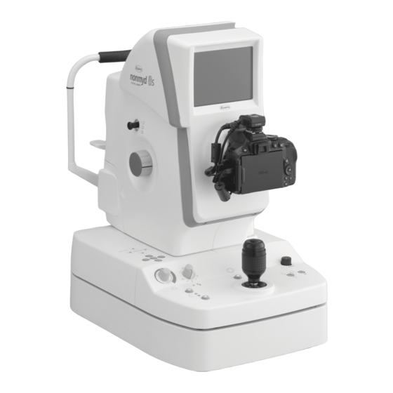
- Page 1 Non-mydriatic Retinal Camera KOWA INSTRUCTION MANUAL KOWA nonmyd 8s US/EU...
-
Page 3: Introduction
Introduction Congratulations on your purchase of the KOWA nonmyd 8s. The KOWA nonmyd 8s is a non-mydriatic retinal camera for retinal photography. This manual provides a description of the operating procedures of the KOWA nonmyd 8s and important precautions to be observed during its use. - Page 4 If any abnormal smell, sound, overheating or smoke should be detected, make sure to turn OFF the instrument immediately and then unplug the instrument from the power outlet. Con- tinued use of the instrument may cause a fire or instrument malfunction. Contact Kowa or your Kowa dealer for inspection immediately.
- Page 5 Caution Do not pull on the power supply cable when unplugging the instrument from the power outlet. Doing so may damage the cable and cause a fire or electric shock. Make sure to hold the pow- er plug when unplugging the instrument. Do not install the instrument on an unstable location such as on a shaky base or a tilting sur- face.
-
Page 6: Meanings Of Symbols
Meanings of Symbols Symbol for “Type B applied part”. Symbol for “Caution”. Symbol for “Power ON”. Symbol for “Warning High-voltage”. Symbol for “Power OFF”. Symbol for “Caution High-temperature”. Symbol for “Follow instruction for use”. Symbol for “MANUFACTURER”. Symbol for “AUTHORISED REPRESENTATIVE IN THE EUROPEAN COMMUNITY”. -
Page 7: Operating Precautions
3) Kowa is not liable for malfunctions and/or damages resulting from maintenance and/or repairs performed by the third party other than an agent authorized by Kowa. 4) Kowa is not liable for malfunctions and/or damages resulting from maintenance and/or repairs using parts other than repair parts specified by Kowa. -
Page 8: Operational Considerations For A Hospital Grade Electrical Instrument (Safety And Accident Prevention)
5) The instrument must be cleaned prior to use so that there will be no problem when using it again. 6. In case of a problem or malfunction, stop the operation and contact Kowa or your Kowa dealer for repair. -
Page 9: Precautions: Use Of Medical Electrical Systems
This instrument constitutes a medical electric system by connecting with the following optional accessories or products. - Numeric key pad (option) In order to select internal fixation target in Mosaic, it is used connecting with USB connector of the KOWA nonmyd 8s. - Personal computer It is used in order to acquire the images taken by the KOWA nonmyd 8s. - Page 10 Precautions: Use of Medical Electrical Systems Combinations of medical electrical equipment and non- medical electrical equipment IEC 60601-1 Annex I “ME system aspects” describes the summary of situations that could occur when different combinations of equipment are used in various medical environments. The brief overview of IEC 60601-1 Annex I is shown below.
- Page 11 Precautions: Use of Medical Electrical Systems Medically used room Examples of Practical means of Non- possible causes Inside the compliance Outside the Situation No. medically for exceeding PATIENT Apply 16.5 in all PATIENT used room LEAKAGE ENVIRON- situations ENVIRONMENT CURRENT limits MENT Mains Mains...
-
Page 12: Electromagnetic Compatibility
Electromagnetic Compatibility This instrument is a medical electrical instrument. Medical electrical instruments require special attention to electromagnetic compatibility (EMC). The following section describes the EMC and precautions regarding this instrument. When installing or using this instrument, read the description carefully and follow the directions described. *The EMC of this instrument was tested based on IEC 60601-1-2 (EN 60601-1-2). - Page 13 Guidance and manufacturer’s declaration - electromagnetic emissions The KOWA nonmyd 8s is intended for use in the electromagnetic environment specified below. The customer or the user of the KOWA nonmyd 8s should assure that it is used in such an environment. Emissions test...
- Page 14 RF transmitters, an electromagnetic site survey should be considered. If the measured field strength in the location in which the KOWA nonmyd 8s is used exceeds the applicable RF compliance level above, the KOWA nonmyd 8s should be observed to verify normal operation. If abnormal performance is observed, additional measures may be necessary, such as reconfiguring or relocating the KOWA nonmyd 8s.
-
Page 15: Components And Supplies
Components and Supplies Main Unit and Accessories Main unit: 1 USB cable USB cable Power supply cable, 3 m: 1 Digital camera: 1 (Type A―B, 3 m): 1 (Type A―Mini-B, 3 m): 1 Blower: 1 SD memory card: 1 Dust cover: 1 Chin rest paper retaining Fuses: 2 Chin rest paper: 1... -
Page 16: Table Of Contents
Contents Introduction ............I Preparations for Photography ..... 14 Meanings of Symbols ........IV Preparing the Instrument ..........14 Preparations for Patient’s Eye Examination ....14 Operating Precautions ........V Operational Procedure in Photography ..15 Operational Considerations for a Hospital Grade Electrical Instrument (Safety and Accident Prevention) ..VI Basic Photography .............15 Precautions for Continuous Photography ....21 Precautions: Use of Medical Electrical Systems .. -
Page 17: Instrument Description
Instrument Description 1.1 Intended Use/Indications for use The KOWA nonmyd 8s is intended for use with retinal image capturing without mydriatic. 1.2 Overview This system is an instrument that enables retinal examination and retinal image capturing using infrared rays without re- quiring the patients to take any mydriatics. -
Page 18: Name And Function Of Each Part
System Description 1.5 Name and Function of Each Part Diopter compensation knob If you cannot focus by turn- ing the focusing knob, pull LCD monitor the diopter compensation Black-and-white live image knob to make (-) or (+) com- of the anterior segment or pensation until the focus retina appears for you to point is found. - Page 19 System Description Operation panel Retinal observation light Anterior segment button intensity control knob Pressing this button switches the image shown on the LCD monitor between anterior segment and retina. The button illuminates when the anterior seg- Used for adjusting light intensity ment is selected.
- Page 20 System Description Anterior segment observation lamp Infrared LED lamp that illu- minates when the anterior segment is observed. Forehead rest Used for resting the patient’s forehead against it. Eye level mark Focusing knobs Used for aligning the verti- cal position of the patient’s Used for focusing.
- Page 21 System Description Power supply unit Power switch Cable clamps | : ON : OFF Fuse holders Used for holding cables to keep them from being disconnected. Electrical supply inlet Air vent Image output terminal (Type B) Used for connecting a PC to the instrument using the USB cable supplied. Image data output terminal (Type mini-B) When you wish to acquire both captured images and data, use the USB cable supplied with this instrument to connect a PC to the instrument.
- Page 22 System Description LCD monitor indications Anterior segment observation display COLOR BLUE Anterior Left eye Right eye : R “ANTERIOR” indicates that the instrument is currently showing the anterior segment observation display. Anterior segment observation : ANTERIOR Used for a small pupil diameter. Retinal observation : none : SP...
- Page 23 System Description Retinal observation display COLOR Data Transfer in Progress Charging Fixation target position Data Transfer in Progress This indicates the fixation target position currently turned on. This is indicated while the instrument is transferring data. Posterior : CENTRAL Optic disc : DISC Charging indicator Center of macula...
-
Page 24: Preparation
Preparation 2.1 Installation 1 Place the instrument on a motorized table (optional device). Observe the following precautions when moving the instrument. • Tighten the optical component fixing screw. • Put your hands under the power supply unit and lift the instrument as shown in the right figure. - Page 25 The digital camera needs to be disconnected from the instrument when the instrument is to be relocated or the inside of the digital camera is to be cleaned. In such a case, contact Kowa or your Kowa dealer in advance for the correct procedures and precautions for detaching the digital camera.
-
Page 26: Installing External Device (Optional Pc)
IEC 60601-1/EN 60601-1. Should you have any question, contact Kowa or your Kowa dealership. Connection of the instrument to an IT-NETWORK that includes external devices, or subsequent changes to the IT-NETWORK could introduce unexpected problems. -
Page 27: Saving Captured Images
Captured images saved in an SD memory card may be displayed on the LCD monitor of the digital camera. The images may be printed out after connecting the digital camera to a printer. Contact Kowa or your Kowa dealer for details. -
Page 28: Basic Operation
Basic Operation 4.1 Optical Component Fixing Screw Completely loosen the optical component fixing screw before starting any photography using this instrument. tighten Completely tighten the optical component fixing screw before moving this instrument to other installation site. loosen 4.2 Coarse Motion: Moving the Optical Component for a Long Distance In order to move the optical component for a long distance, move the control lever lengthwise or crosswise while holding the lever tightly in upright position. -
Page 29: Preparations For Photography
Preparations for Photography 5.1 Preparing the Instrument 1 Make sure that the optical component fixing screw is completely loosened. 2 Make sure that the instrument is correctly connected to the PC. Make sure that the PC is turned ON and the application software is started. 3 Remove the objective lens cap. -
Page 30: Operational Procedure In Photography
The chart shown below describes the operational procedure in Basic photography. Details of items shown in the chart are described on the following pages. Preparations Preparing Kowa nonmyd 8s Turn ON the power switch Preparations for patient’s eye examination photography... - Page 31 Operational Procedure in Photography 6.1.1 Selecting an internal fixation target Use the internal fixation target selection button to select an internal fixation target that you use for retinal observation. Continuously pressing the button cycles through the targets as shown in the figure below.
- Page 32 Operational Procedure in Photography 6.1.4 Alignment (Anterior) Pull the optical component as close as possible to you; then, move the optical component leftward/rightward or upward/downward in order to capture the pupil at the center of the LCD monitor. Beginning of alignment Rotate the focusing knob until the black line engraved on the knob faces upwards.
- Page 33 Operational Procedure in Photography 6.1.5 Checking pupil diameter Check the condition of dilation by comparing the patient’s pupil diameter against the pupil diameter aid. Change the flash intensity as required depending on the mydriatic state. If the patient’s pupil diameter is smaller than that shown by the pupil diameter aid, press the SP button to proceed to small pupil photography.
- Page 34 Operational Procedure in Photography 6.1.7 Checking eyelids and eyelashes The eyelids or eyelashes intruding the pupil area interferes photography. In such a case: Instruct the patient to widely open his or her eyes, or You or your assistant help the patient keep the eye wide open. 〇...
- Page 35 Operational Procedure in Photography 6.1.9 Adjusting observation light intensity Retinal observation light intensity control knob When the retinal image, focus bars, and working dots are not clearly shown, use the retinal observation light intensity control knob to adjust image brightness. For details of the LCD monitor brightness and contrast adjustment, refer to “9.4.5 MONITOR BRIGHTNESS/CONTRAST”.
-
Page 36: Precautions For Continuous Photography
Operational Procedure in Photography 6.1.13 Photography After alignment and focusing are completed, take a photograph by pressing the shutter button. Pictures will be stored in the connected SD memory card or PC. For viewing the pictures in a PC, refer to “Installation manual (filing software)”. -
Page 37: Advanced Photography
7.1 Mosaic Photography Mosaic photography has its own internal fixation target selection and positioning different from that of Normal or SP. In this section these differences are described. Preparing KOWA nonmyd 8s Preparations for patient’s eye examination Preparations Turn ON the power switch... - Page 38 Advanced Photography 7.1.1 Selecting mosaic photography Press the mosaic button (the button above “MENU” button). You can switch SP during mosaic photography. 7.1.2 Selecting an internal fixation target The internal fixation target selection button becomes disabled during mosaic photography. Mosaic photography has two types of internal fixation target setting methods, “AUTO”...
- Page 39 Advanced Photography Switching the internal fixation target in mosaic photography – Use in manual mode Anterior segment observation display Retinal observation display Select manual mode in order to select the position of your choice in mosaic photography. For details of the setting, refer to “9.3 Mosaic Internal Fixation Target Setting (Switching the Internal Fixation Target in Mosaic Photography)”.
- Page 40 Advanced Photography 7.1.3 Alignment and focusing In mosaic photography, align for anterior segment observation only, switch to retinal observation without changing the po- sition of the instrument, check that the patient eye is correctly fixed; then, photograph. However, when you see excessive flare during retinal observation, position the digital camera appropriately before photo- graphing.
-
Page 41: External Fixation Target
Advanced Photography 7.2 External Fixation Target When fixation of the patient’s eye using the internal fixation target cannot be accomplished, use the external fixation tar- get (optional accessory) to enable fixation using other side of the eye. 7.2.1 Installing the external fixation target 1 Aligning the groove on the external fixation target mount and the chin rest, tighten the two mounting screws to lock the external fixation target. -
Page 42: Troubleshooting
Troubleshooting Examples of retinal photograph Possible cause Remedies Dark shadow or bright reflection ap- pears at the top or bottom of the im- The objective lens is posi- age. tioned too high to the pa- tient’s eye. Perform all alignment steps to obtain a clear retinal image with consistent brightness. - Page 43 Troubleshooting Irregularity Possible cause Remedies Adjust the focus using the retinal image since A diopter compensation lens is Focus bars do not appear. focus bars do not appear when a diopter com- inserted. pensation lens is in use. The flash lamp turns ON but a black The shutter speed of the digital image or partially chipped image is Set the shutter speed of digital camera to 1/25 sec.
- Page 44 Charged voltage does not reach the lower limit. POWER OFF & CALL SERVICE PERSON There could be a failure of an internal circuit. Please contact Kowa or your Kowa dealer. ERROR : 6 Initialization to the internal memory failed. POWER OFF & CALL SERVICE PERSON There could be a failure of an internal circuit.
-
Page 45: Menu Operation
Menu Operation 9.1 Starting Menu Press down the menu button for approx. two seconds to access menu mode. Menu buttons Use menu buttons “p, q, t, and u” in menu mode. 9.2 Objective Lens Cleaning Lamp Objective lens cleaning lamp illuminates when you press “ t ” button to “ON” while “LAMP FOR LENS CLEANING”... - Page 46 Menu Operation 9.3.2 Settings of auto mode Press the menu button while “AUTO” is highlighted to access “MOSAIC INT- FIX AUTO MODE SETTING”. Pressing the menu button while “AUTO MODE SETTING” is highlighted makes one of the numbers shown under “PHOTO LOCATION ON THE RIGHT EYE”...
-
Page 47: Other Setting Menu
Menu Operation When you select “NO” for the “MIRROR SELECTION”, illuminating orders are as shown below. Setting of illuminating orders Right eye Left eye Select “SET” and press menu button in “MOSAIC INT-FIX AUTO MODE SETTING” to save the settings and return to menu item selection. - Page 48 Menu Operation 9.4.2 SLEEP MODE You can select “SLEEP MODE” (power saving mode) as the initial power mode when the power is turned ON. When this instrument is not operated for a certain period of time (approximately 10 minutes) it goes into “SLEEP MODE”.
- Page 49 Menu Operation 9.4.5 MONITOR BRIGHTNESS/CONTRAST Press the menu button while “MONITOR BRIGHTNESS” or “MONITOR CONTRAST” is selected to display an observation image. Use the image to set the LCD monitor screen brightness or contrast. Press “ p ” or “ q ” menu buttons to increase or decrease the brightness or contrast.
-
Page 50: Maintenance And Inspection
5. When condensation occurs repeatedly, lenses may get moldy. When such a case has occurred to you, contact Kowa or your Kowa dealer. 6. Disconnect the power supply cable when the instrument is not used for an extended period of time. -
Page 51: Regular Inspection
Maintenance and Inspection 10.3 Regular Inspection In order to use this instrument safely over its useful life, we recommend you to have it inspected annually. Contact Kowa or your Kowa dealer for details and cost of inspections. 1. Records of each settings 2. -
Page 52: Disinfection
Maintenance and Inspection 10.5 Disinfection Wipe the forehead rest with rubbing alcohol as soon as a patient completes the examination. Also wipe the chin rest with rubbing alcohol when no chin rest paper is used. 10.6 Outer Cleaning Do not wipe the outer surface of the instrument with solvents Caution such as benzene, or ether. - Page 53 It normally turns OFF completely within 3 minutes after the power is turned OFF. If it does not turn OFF even after above period of time, contact Kowa or your Kowa dealer as it may carry a risk of failure.
-
Page 54: Fuse Replacement
(clockwise) and install it in place. 6 Connect the power supply cable plug to the power outlet. 10.9 Refilling and Replacing Consumables Order spare parts by purchase order numbers listed below to Kowa or your Kowa dealer. Part name Purchase order number... -
Page 55: Specifications
Specifications 45° Field angle * Some eyes may cause a flare around their circumference. Tolerance of pixel pitch on fundus Normal image : S* (6.3 μm ± 7%) (ISO 10940) : L* (3.1 μm ± 7%) Working distance 30 mm φ... -
Page 56: Technical Information
Technical Information 12.1 Imaging Conditions Output This instrument outputs the imaging conditions from the image output terminal (Type B)/image data output terminal (Type mini-B). If you want to read the imaging conditions using application software other than that provided with the instru- ment, refer to the specifications below: For this purpose, you need to install FTDI “Direct (D2XX) driver Ver 2.04.06 or later”... - Page 57 For EU Market...
- Page 60 E-mai l : life@kowa.co.jp U R L : http://www.kowamedical.com/ U R L : http://www.kowa.co.jp/e-life/ Kowa Company, Ltd. Chofu Factory 3-1, Chofugaoka 3-chome, Chofu, Tokyo 182-0021, Japan © 2015-2017 Kowa Company, Ltd. All rights reserved. K9L63 V1.6KE 171120 KW Printed in Japan...