Table of Contents
Advertisement
Quick Links
Advertisement
Table of Contents
Troubleshooting

Related Manuals for Kowa VX-10A

Summary of Contents for Kowa VX-10A
- Page 1 FUNDUS CAMERA KOWA INSTRUCTION MANUAL KOWA VX-10α...
-
Page 3: Operational Considerations For Safety
Introduction Introduction Introduction This manual provides a description of the operating procedures of KOWA along with important precautions to be observed during its use. Please read this entire manual carefully to assure that the instrument can demonstrate its full capabilities and work safely. After you have finished reading, please keep this manual in an easily accessible location near the instrument for future reference. - Page 4 If it should continue in use, a fire may break out on the instrument resulting in its malfunctioning. Contact Kowa or your Kowa dealer for inspection immediatery. When replacing the flash lamp or observation lamp, be sure to turn OFF the main power switch and unplug it from the power outlet, and wait for 30 minutes or more.
- Page 5 Introduction Caution Do not pull the power supply cable when unplugging the instrument from the power outlet. Doing so may damage the cable and cause a fire or electrical shock. Do not plug or unplug the power cord with wet hand. Otherwise, it may cause electrical shock.
- Page 6 Introduction Air vent Air vent Air vent Air vent Air vent Caution A. Keep your fingers off the spaces between the sliding base and the base’s power housing when operating the control lever. There is a fear of your fingers being caught and injured when the sliding base moves. Caution B.
-
Page 7: Indication Of Caution Label
Introduction Indication of caution label Symbol for “Type B applied part” Symbol for “Caution” Symbol for “OFF” Symbol for “Warning High-voltage” Symbol for “ON” Symbol for “Caution High-temperature” Symbol for "Follow instruction for use" Symbol for “MANUFACTURER” Symbol for “AUTHORISED REPRESENTATIVE IN THE EUROPEAN COMMUNITY”... -
Page 8: Precautions In Operation
Replacement of the Aluminum Electrolytic caused by improvement, repair or maintenance ren- Capacitor dered by the third party other than Kowa and its autho- The aluminum electrolytic capacitor for the flash lamp, rized agent. ● Kowa is not responsible for any failure(s) or damage(s) which is used in the power supply section of this instru- ment, is a component requiring regular replacements. -
Page 9: Precautions: Use Of Medical Electrical System
This instrument constitutes medical Electric system by connecting with the following products. - Personal computer It is used in order to acquire the electronic images taken by KOWA . An application software KOWA VK-2 for instance should be installed on the PC. - Page 10 Introduction ● Combinations of medical electrical equipment and non- medical electrical equipment IEC 60601-1 Annex I “ME system aspects” describes the summary of situations that could occur when different combinations of equipment are used in various medical environments. The brief overview of IEC 60601-1 Annex I is shown below. Medically used room Examples of Practical means of...
- Page 11 Introduction Precautions: use of medical electrical system Medically used room Examples of Practical means of Non- possible causes Inside the compliance Outside the Situation No. medically for exceeding PATIENT Apply 16.5 in all PATIENT used room LEAKAGE ENVIRON- situations ENVIRONMENT CURRENT limits MENT Mains...
-
Page 12: Operational (Safety And Hazard Prevention) Considerations For Hospital Grade Electrical Equipment
(6) In case it is expected to be not used for a long period of time, keep the camera back with batteries unloaded from it. 6. If it has some trouble, a label describing the trouble should be affixed on the instrument and contact Kowa or your Kowa dealer for repair. -
Page 13: Accessories
Introduction Accessories External fixation lamp: Dust cover: 1 pc. Instruction manual: 1 Quick manual: 1 1 pc. Hexagon wrench:2 pcs. Pin: 2 pcs. Chin rest paper: 1 set Fuse: 2 pcs. Observation lamp: 1 pc. Blower: 1 pc. Internal fixation target Grip (option) Data card: (option) (option) - Page 14 Introduction P0-12...
-
Page 15: Table Of Contents
Introduction KOWA KOWA Summary of equipment Preparatory procedure Basic photography Other practical photography Handy features Troubleshooting Maintenance and inspection Specifications Technical references Photochemical Hazard (ISO 15004) Electromagnetic Compatibility (IEC 60601-1-2) P0-13... - Page 16 3. Basic photography ......P3-1 7-11 Repairing the Instrument ......P7-6 Operation procedure flowchart ..... P3-1 7-12 KOWA Daily Inspection Table..P7-6 Non-mydriatic photography ......P3-2 Mydriatic color photography ......P3-6 8. Specifications ........P8-1 Mydriatic fluorescein angiography ....P3-10 9.
-
Page 17: 1-1 Purpose Of Use And Effectiveness
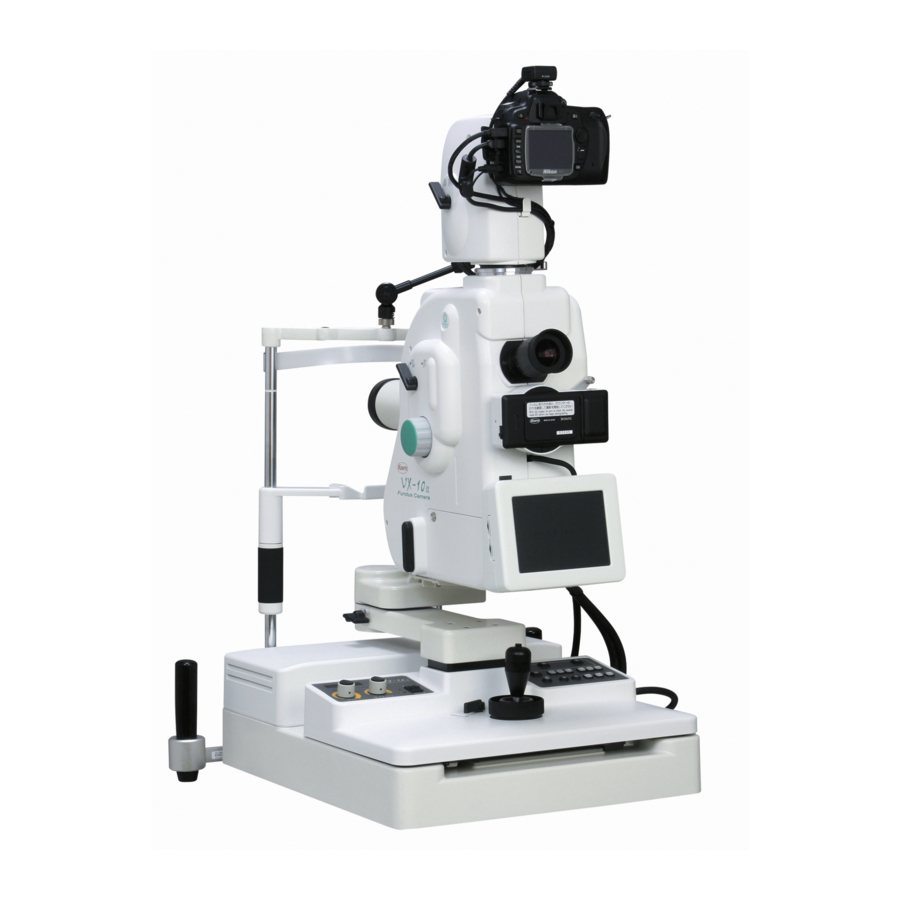
Purpose of use and effectiveness KOWA is intended for taking pictures of fundus images with mydriatic or without mydriatic. General information This equipment is a fundus camera which is capable of mydriatic and non-mydriatic photography with two angles of view: 50° and 30° (45° and 27° for non-mydriatic photography). You can record photographic data with 35-mm film, video and so forth. - Page 18 1. Summary of equipment Name and function of each part Objective lens Lower camera back mount (35-mm mount) A large aspherical lens with protective lens cap A mount for fixing 35-mm camera back. Cord- for keeping lens surface from dirt and dust. less connection provided of the camera back to Focusing knobs the main camera unit.
- Page 19 1. Summary of equipment Power cord Field angle knob The shape of the plug varies according to the Used to select a field angle of either 50° or 30° input voltage. (45° or 27° for non- mydriatic photography). External fixation lamp Data card slot Used to guide the examined eye's fixation to An insertion slot for written data card to be pho-...
- Page 20 1. Summary of equipment Horizontal lock lever Flash intensity compensation knob Upon operation of this lever, the rotating arm will Used to adjust flash intensity level. be locked. Working camera back indicator Tilting handle This indicator comes on indicating which cam- By turning this handle, the main camera unit will era back of upper or lower ones is in work, be tilted vertically.
- Page 21 1. Summary of equipment Non-mydriatic button S.P. button Used to select non-mydriatic color photography. Used to select small pupil photography in mydri- Fluorescein Angiography filter button atic fluorescein mode and mydriatic color mode. LCD monitoring button Used to insert or remove fluorescein filter in mydriatic fluorescein angiography mode.
- Page 22 Caution After installing the instrument, do not raise the instrument. This instrument may be shaky and fall over, causing a bodily injury. When you change a installing position, please contact Kowa or your Kowa dealer in advance. The power line from the power outlet must be exclusively connected to the fundus camera. If the...
- Page 23 2. Preparatory procedure Loading 35-mm camera back’s batteries 1) Press the battery cover in the direction marked “▲” and open the battery cover. 2) Load new batteries. 3) For checking the remaining battery charge level, keep pressing the battery check button with the power switch being turned OFF, provided that a film is not being loaded.
-
Page 24: Preparatory Procedure
2. Preparatory procedure Mounting 35-mm camera back 1) To mount/ turn the handle downward 1) Mount the camera back with the limit pin facing upward on the main camera unit’s lower camera back mount and fix it by turning the handle downward. 2) To dismount it, turn the handle upward. - Page 25 2. Preparatory procedure Types of available films Recommended 35-mm camera back films Photography mode Type of film Film speed Development Color photography Reversal film Color ISO 100 Standard Negative film B&W ISO 400 3 X development Fluorescein angiography Negative film B&W ISO 1600 Standard...
- Page 26 2. Preparatory procedure Warning Carefully operate the fundus camera so that the camera will not get in touch with the patient’s face (eye, nose, so forth). Prohibitory Caution Be careful for a patient to be unable to touch the instrument except for grips and a head band. In operating the fundus camera, keep your fingers off the spaces or gaps between (1) the base and power unit, (2) the main camera unit and horizontal arm, (3) tilt arm and tilt moving portion, (4) the power unit and chin rest support, (5) the power unit and horizontal arm, and (6) the objec-...
- Page 27 Operation procedure flowchart Select a desired photography mode by button Non-mydriatic Mydriatic color Mydriatic fluorescein Optical viewfinder adjustment Select photographic optical path and check the number of unexposed frames Check the pupil Check the pupil dilation diameter Flash intensity compensation Examined eye dioptric compensation (In case the examined eye diopter is minus (-) 12D or less or plus (+) 13D or more) Examined eye height positioning (alignment)
-
Page 28: Basic Photography
3. Basic photography Non-mydriatic photography This paragraph describes the method of non-mydriatic fundus photography. To let the examined eye dilate sponta- neously, reduce room’s luminance as low as you can barely read a newspaper. 1) Select “Non-mydriatic” on the mode select button on the right-hand panel. 2) Select a desired photography optical path by camera select switch on the left-hand panel. - Page 29 3. Basic photography 5) Checking the pupil’s diameter. Insert dioptric lens for anterior segment by Anterior segment select button. Pull the fundus camera toward you as closely as the anterior area of the eye is almost seen. For adjustment, move the fundus camera backward and forward to align the periphery of the patient’s iris to the monitor’s vertical line.
- Page 30 3. Basic photography 6) Compensating the examined eye’s diopter. Insert diopter lens by diopter lens button. Examined eye’s diopter –12D to +13D : Diopter lens is not necessary. –10D to –32D : Insert minus (–) diopter lens. +10D to +35D : Insert plus (+) diopter lens. 7) Setting the examined eye’s position.
- Page 31 3. Basic photography n Flash intensity. Exposure can be automatically adjusted to have a standard intensity for each ■ Flash intensity compensation knob / display photography. But it is expected that excess or deficiency in exposure caused by the difference in dilation, color of iris, etc. will cause some deviation from the standard state.
- Page 32 3. Basic photography Mydriatic color photography This paragraph describes a method of mydriatic color fundus photography. Reduce the room’s luminance as low as you can barely read a newspaper. 1) Select “Color” by the mode select button on the right-hand panel. 2) Adjust optical viewfinder diopter.
- Page 33 3. Basic photography 6) Compensating the examined eye’s diopter. Insert diopter lens by diopter lens button. Examined eye’s diopter –12D to +13D : Diopter lens is not necessary. –10D to –32D : Insert minus (–) diopter lens. +10D to +35D : Insert plus (+) diopter lens. 7) Setting the examined eye’s position.
- Page 34 3. Basic photography 10) Adjusting the focus. Turn the focusing knob such that luminous lines for focusing detection can be arranged in a straight line as il- lustrated in the drawings below. 10) Adjust the focus Luminous lines for focusing detection Luminous lines for focusing Adjust lines to be arranged detection...
- Page 35 3. Basic photography Observation through the optical viewfinder Perform fine adjustment while looking into the optical viewfinder. For better photography, be careful about the following: Photograph Quality of view Recommended remedy White reflection at top Camera positioned too high. Camera positioned too low. White reflection at bottom Eyelid of examined eye overhanging.
- Page 36 3. Basic photography Mydriatic fluorescein angiography This paragraph describes a method of mydriatic fundus fluorescein angiography. Reduce room’s luminance as low as you can barely read a newspaper. Steps 2) through 10) are the same with those of “3-3 Mydriatic color photography.” For more information, see the items of “3-3 Mydriatic color photography”.
- Page 37 3. Basic photography Fluorescein angiography at the rate of one frame per second. ■ 1 frame per second photography In case of consecutively photographing at an interval of 1 second, keep pressing the shutter button. Some camera backs may not support this photography. n Automatic insertion of exciter filter.
- Page 38 Photography of enlarged image 4) Switching field angle This paragraph describes the method of photographing enlarged image. On this equipment, you can select from the field angles of 50° and 30° in mydriatic color and mydriatic fluorescein modes, and from those of 45° and 27° in non-mydriatic mode. 1) Operate according to the paragraphs of “3.
- Page 39 4. Other practical photography n Small pupil mode • The pupil with a minimum diameter of 5.5 mm can be photographed in mydriatic mode. When in small pupil mode, the diameter of pupil to be photographed can be reduced to a minimum diameter to 4.0 •...
-
Page 40: Other Practical Photography
4. Other practical photography Photography of data card In this paragraph, methods of photographing a data card on 35-mm film are described. Photography of data card You can photograph a data card on 35-mm camera back. The data card is sold separately as an option. - Page 41 LCD monitoring mode (“Mydriatic color” and “FA” mode) This paragraph describes the method of performing mydriatic photography watching LCD monitor instead of looking into viewfinder as if doing non-mydriatic photography. This feature allows you to photograph without diopter adjust- ment. Also a patient becomes free from dazzling observation light since it uses infrared light in the mydriatic color mode and reduces the intensity of observation light in the mydriatic fluorescein mode.
-
Page 42: External Image Input Display Function
5. Handy features External image input display function In this paragraph, the method of displaying the images of an external imaging device is described. With this func- tion, you can use the LCD monitor of this unit to review the fundus images from the external imaging device located remotely. -
Page 43: Changing Initial Settings
5. Handy features Changing initial settings This paragraph describes initialization of this equipment. This equipment will be more conveniently utilized by changing initial settings. Initial settings can be changed by changing over the switches from one position to the other. List of switches at the back of panel Description Non-... - Page 44 This paragraph describes remedies for any irregularity occurring on this equipment. If any irregularity should occur on this equipment, check the following before contacting your Kowa dealer where you purchased it. Irregularity Check item Remedy Non-mydriatic mode wrongly selected. Switch to “Color” mode.
-
Page 45: Troubleshooting
Power switch was repeatedly turned 1” should still appear, stop the equip- indicator. ON/OFF. ment and contact your Kowa dealer where you purchased it. After turning OFF the power, wait for ten seconds before turning it ON again. If Err 2 indicated on panel's... -
Page 46: Troubleshooting
Dark spots appearing in identical locations of any picture Please contact your Kowa dealer where Inside of camera fouled with dust. you purchased it, asking for recover. P6-3... -
Page 47: Maintenance And Inspection
Wait for a while until the lens is defogged, and after defogging, start photography. Otherwise, pictures taken may become out of focus. • If it has been repeatedly fogged, the lens may get moldy. In this case, contact Kowa or Kowa dealer where you purchased it. -
Page 48: Inspecting/Cleaning The Objective Lens
After this step, fully wipe the lens with the solution all over again. If dirt should still resist cleaning, contact your Kowa dealer where you purchased the instrument. 3) Blow off by the accessory blower... -
Page 49: Replacing Observation Lamp With A New One
7. Maintenance and inspection Replacing observation lamp 2) Remove the cover with a new one The light source cover s screw The light source cover s screw 1) Turn OFF the power switch before unplugging from the power outlet. 2) Loosen the light source cover’s screw by coin or flathead screwdriver for removal. -
Page 50: Replacing Flash Lamp With A New One
7. Maintenance and inspection Replacing flash lamp with a new one 1) Turn OFF the power switch before unplugging from the power outlet. 2) Remove the lamp cover by the same procedure as that for replacing the observation lamp to expose the flash lamp. -
Page 51: Replacing Fuse With A New One
7. Maintenance and inspection Replacing fuse with a new one 1) Turn OFF the power switch before unplugging from the power outlet. 2) Turn the power unit's fuse holders by flathead screwdriver 2) Fuse holders counterclockwise to take out fuses in service. 3) Replace with new fuses and close the fuse holders. -
Page 52: Repairing The Instrument
6. The captured image using the standard model eye (OD) 7. The captured photograph using the standard model eye (OD) 8. Performance and flash intensity For information about what is to be inspected and costs, please contact Kowa or your Kowa dealer. 7-11 Repairing the Instrument... - Page 53 Mydriatic 50° / 30° • Field angle Non-mydriatic 45° / 27° • Working distance 39 mm (from examined eye to front of objective lens) – 12D ~ + 13D • Range of Compensation of – – 10D ~ – 32D examined eye + 10D ~ + 35D •...
- Page 54 TRIG–IN(STROBE) TRIG–OUT(TRIG) Dedicated synchronous cables K9L-SC48 (D-SUB ~ D-SUB ) 5m For connecting VK2 K9L-SC48D (K9L-SC48 + BNC Cable N = 2) 5m For connecting VK2D Caution If you intend to use external synchronization connector, please contact Kowa distributer. P9-1...
- Page 55 24 h. This will apply particularly if the eye has been exposed to retinal pho- tography. Should you have any question (e.g., ratio of the variable intensity to the maximum intensity), contact us or your Kowa dealer. P10-1...
- Page 56 Do not assemble into this instrument any optional or accessory parts other than those designated by Kowa. Otherwise, this instrument may be adversely affected by other instrument resulting in malfunction- ing, or the latter itself may malfunction.
- Page 57 Guidance and manufacturer's declaration - electromagnetic emissions The KOWA is intended for use in the electromagnetic environment specified below. The customer or the user of the KOWA should assure that it is used in such an environment. Emissions test Compliance...
-
Page 58: Electromagnetic Compatibility
Guidance and manufacturer's declaration - electromagnetic immunity The KOWA is intended for use in the electromagnetic environment specified below. The customer or the user of the KOWA should assure that it is used in such an environment. Immunity test IEC 60601 test level... - Page 59 To assess the electromagnetic environment due to fixed RF transmitters, an electromagnetic site survey should be considered. If the measured field strength in the location in which the KOWA is used exceeds the applicable RF compliance level above, the KOWA should be observed to verify normal operation.
-
Page 60: (Iec 60601-1-2)
The customer or the user of the KOWA can help prevent electromagnetic interference by maintaining a minimum distance between portable and mobile RF communications equipment (transmitters) and the KOWA recommended below, according to the maximum output power of the communications equipment. - Page 61 11. Electromagnetic Compatibility (IEC 60601-1-2) For EU market. P11-6...
- Page 62 11. Electromagnetic Compatibility (IEC 60601-1-2) P11-7...
- Page 64 Kowa Company, Ltd. Chofu Factory 3-1, Chofugaoka 3-chome, Chofu, Tokyo 182-0021, Japan Kowa Company, Ltd. Hamamatsu Factory 3-1, Shinmiyakoda 1-chome, Kita-ku, Hamamatsu, Shizuoka 431-2103, Japan © 2009-2016 Kowa Company, Ltd. All rights reserved. K9L48B V2.1E 160601 MS Printed on recycled paper. Printed in Japan...
Need help?
Do you have a question about the VX-10A and is the answer not in the manual?
Questions and answers