Advertisement
Quick Links
Advertisement

Subscribe to Our Youtube Channel
Related Manuals for Kowa VX-10a


Summary of Contents for Kowa VX-10a
- Page 1 FUNDUS CAMERA KOWA INSTRUCTION MANUAL KOWA VX-10a...
- Page 3 INTRODUCTION This manual provides a description of the operating procedures of KOWA along with important precautions to be observed during its use. Please read this entire manual carefully to assure that the instrument can demonstrate its full capabilities and be used effectively. After you have finished reading it, please keep it in an easily accessible location near the instrument for future's reference.
- Page 4 Install at a location away from, for instance, a cup containing liquid. If liquid should be spilled into the instrument, there may occur electrical shock. If so, turn OFF the instrument and then unplug it from the socket. Contact your Kowa dealer where you purchased it or Prohibitory your nearest repair shop for inspection.
- Page 5 INTRODUCTION Caution Pull off the plug from the power outlet without giving a pull. Prohibitory Do not plug or unplug the power cord with wet hand. Prohibitory Do not install the power unit at unstable locations, for instance, on a shaky base or a tilting surface. Otherwise, if it should drop off or fall over, the human body may be injured.
- Page 6 INTRODUCTION Caution Keep your fingers off the gap between the base’s power housing and the poles of chin-rest unit. Therefore, instruct the patient not to hold the poles by hand because there is a fear of your fingers being caught and injured. Prohibitory Keep your fingers off the gap between the base’s power housing and the horizontal arm.
- Page 7 INTRODUCTION Air vent Air vent Air vent Air vent Air vent Caution A. Keep your fingers off the spaces between the sliding base and the base’s power housing when operating the control lever. There is a fear of your fingers being caught and injured when the sliding base moves. Caution B.
- Page 8 INTRODUCTION Indication of caution label Warning Warning Caution Pull the plug of Turn off the power Wait until the lamp power cable from switch when the or strobo has Warning Warning Caution wallsocket when lamp or strobo is cooled when the High-temperature fuses are replaced.
- Page 9 Kowa and its autho- ● When disposing, this instrument is categorized rized agent. as industrial waste; therefore, the disposal must ●...
- Page 10 INTRODUCTION Operational (Safety and Hazard prevention) Considerations for hospital Grade Electrical Equipment 1. Only qualified personnel should operate this equipment. 2. The following items shall be considered when installing equipment. (1) Install at a location away from water or accidental splashing. (2) Install at a location which will not be adversely affected by atmospheric pressure, temperature, humidity, ventilation, sunlight, dust, air containing salt, sulfur and other substances, and the like.
- Page 11 INTRODUCTION Combination of medical electrical equipment and non-medical electrical equipment ● IEC 60601-1-1 “Safety requirements for medical electrical systems” describes the components combination grouped into various clinical settings. The brief overview of IEC 60601-1-1 is shown below. Medically used room Feasible solution Non-medically Inside Outside Situation No. (See clause 19 in all used room the PATIENT the PATIENT...
- Page 12 ● Do not use any additional multi-tap receptacle or extension power cable other than those specified to this system by KOWA. ● Power supply to this system or “Multi-tap with Isolation Transformer” must be provided individually. (Do not route the power supply through other multi-tap receptacle to the system or “Multi-tap with Isolation Transformer”.)
- Page 13 INTRODUCTION ACCESSORIES Dust cover: 1 pc. Instruction manual: 1 Attached document: 1 Quick manual: 1 External fixation lamp: Hexagon wrench:2 pcs. Pin: 2 pcs. Chin-rest paper: 1 set 1 pc. Fuse: 2 pcs. Observation lamp: 1 pc. Blower: 1 pc. Detach tool: 1 pc. Internal fixation target Grip (option) Data card: (option) (option) P0-11...
- Page 14 INTRODUCTION P0-12...
- Page 15 INTRODUCTION KOWA KOWA Summary of equipment Preparatory procedure Basic photography Other practical photography Handy features Troubleshooting Daily inspection Specifications Technical references Photochemical Hazard (ISO 15004) Electromagnetic Compatibility (IEC60601-1-2) P0-13 P0-13...
- Page 16 INTRODUCTION ........................P0-1 Operational considerations for safety ..................P0-1 Indication of caution label ...................... P0-6 Precautions in operation ......................P0-7 Operational (Safety and Hazard prevention) Considerations for hospital Grade Electrical Equipment ............P0-8 Precautions: Use of Medical Electrical System ..............P0-10 ACCESSORIES........................P0-11 1.
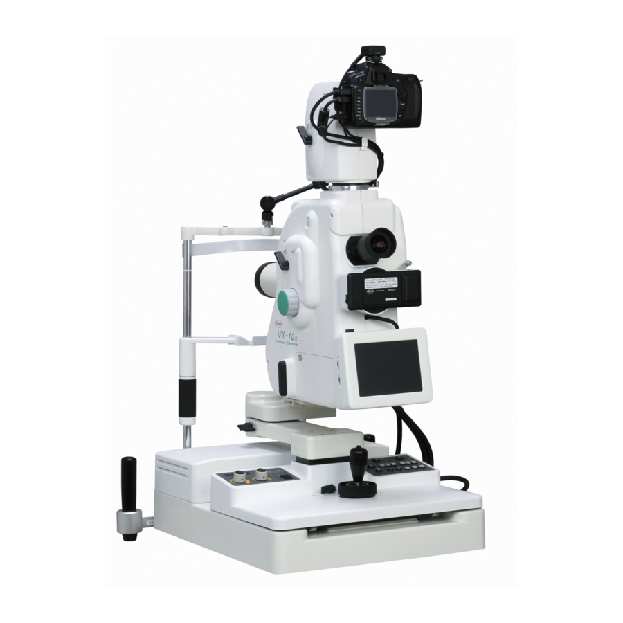
- Page 17 Purpose of use and effectiveness KOWA is intended for taking pictures of fundus images with mydriatic or without mydriatic. General information This equipment is a fundus camera which is capable of mydriatic and non-mydriatic photography with two angles of view: 50° and 30° (45° and 27° for non-mydriatic photography). You can record photographic data with 35-mm film, video and so forth.
- Page 18 1. Summary of equipment Name and function of each part 1 Objective lens 7 Lower camera back mount (35-mm mount) A large aspherical lens with protective lens cap Special mount for fixing 35-mm camera back. for keeping lens surface from dirt and dust. Cordless connection provided of the back to the 2 Focusing knobs main camera unit.
- Page 19 1. Summary of equipment D Power cord L Picture angle knob The shape of the plug varies according to the Used to select a picture angle of either 50° or input voltage. 30° (45° or 27° for non- mydriatic photography). E External eye fixation lamp M Data card slot Used to guide the examined eye's fixation to An insertion slot for written data card to be in- desired direction.
- Page 20 1. Summary of equipment Q Horizontal lock lever Y Flash intensity knob Upon operation of this lever, the rotating arm will Used to adjust flash intensity level. be locked. Z Working camera back indicator R Tilting handle This indicator comes on indicating which cam- By turning this handle, the main camera unit will era back of upper or lower ones is in work, be tilted vertically.
- Page 21 1. Summary of equipment ^ Non-mydriatic switch e S.P. switch Used to switch the system to non-mydriatic Used to switch the system to small pupil pho- color photography. tography in mydriatic fluorescein mode. a Fluorescein Angiography filter switch f LCD monitoring switch Used to insert or remove fluorescein filter in Used to switch the observation system from a mydriatic fluorescein angiography mode.
- Page 22 EN60601-1-1(IEC60601-1-1). The system administrator who builds such system bears all responsibility to have the system comply with requirement of EN60601-1-1(IEC60601-1-1). Should you have any question, contact Kowa sales representative or dealership. Preparatory procedure of fundus camera 1) Remove the objective lens cap.
- Page 23 2. Preparatory procedure 2-4 Loading 35-mm camera back’s batteries 1) Press the battery cover in the direction marked “▲” and open the battery cover. 2) Load new batteries. 3) For checking the remaining battery charge level, keep pressing the battery check button with the power switch being turned OFF, provided that a film is not being loaded.
- Page 24 2. Preparatory procedure 2-5 Mounting 35-mm camera back 1) To mount/ turn the handle downward 1) Mount the camera back with the limit pin facing upward on the main camera unit’s 35mm mount and fix it by turning the handle downward. 2) To dismount it, turn the handle upward. Warning When replacing the camera back, fix it while firmly holding it by hand.
- Page 25 2. Preparatory procedure Types of available films Recommended 35-mm camera back films Photography mode Type of film Film speed Development Color photography Reversal film Color ISO100 Standard Negative film B&W ISO400 3 X development Fluorescein angiography Negative film B&W ISO1600 Standard Negative film B&W ISO400 3 X development Red-free photography Negative film B&W...
- Page 26 2. Preparatory procedure Warning Carefully operate the fundus camera so that the camera will not get in touch with the patient’s face (eye, nose, so forth). Prohibitory Caution In operating the fundus camera, keep your fingers off the spaces or gaps between (1) the base and power unit, (2) the main camera unit and horizontal arm, (3) tilt arm and tilt moving portion, (4) the power unit and chin-rest support, (5) the power unit and horizontal arm, and (6) the objec- tive lens and the patient’s face.
- Page 27 3-1 Operation procedure flowchart Select a desired photography mode by switch. Non-mydriatic Mydriatic color Mydriatic fluorescein Optical viewfinder adjustment Select photographic optical path and check the number of unexposed frames. Check the pupil Check the pupil dilation. diameter. Flash intensity compensation Examined eye dioptric compensation (In case the examined eye diopter is minus (-) 12D or less or plus (+) 13D or more) Examined eye height positioning (alignment) Focusing adjustment...
- Page 28 3. Basic photography 3-2 Non-mydriatic photography This paragraph describes the method of non-mydriatic fundus photography. To let the examined eye dilate sponta- neously, reduce room’s luminance as low as you can scarcely read newspaper. 1) Selecting “Non-mydriatic” on the mode select switch on the right-hand panel. 2) Selecting a desired photography optical path by camera select switch on the left-hand panel.
- Page 29 3-2. Non-mydriatic photography 5) Checking the pupil’s diameter. 1 Insert dioptric lens for anterior chamber by Anterior chamber select switch. 2 Pull the fundus camera toward you as closely as the anterior area of the eye is almost seen. 3 For adjustment, move the fundus camera backward and forward to align the periphery of the patient’s iris to the monitor’s vertical line.
- Page 30 3. Basic photography 6) Compensating the examined eye’s diopter. Insert diopter lens by diopter lens switch. Examined eye’s diopter –12D to +13D : Diopter lens unnecessary. –10D to –32D : Insert minus (–) diopter lens. +10D to +35D : Insert plus (+) diopter lens. 7) Setting the examined eye’s position.
- Page 31 3-2. Non-mydriatic photography n Flash intensity. ■ Flash intensity knob / display Exposure can be automatically adjusted to have a standard intensity for each photography. But it is expected that excess or deficiency in exposure caused by the difference in dilation, color of iris, etc. will cause some deviation from the standard state.
- Page 32 3. Basic photography 3-3 Mydriatic color photography This paragraph describes a method of mydriatic color fundus photography. Reduce the room’s luminance as low as you can scarcely read newspaper. 1) Select “Color” by the mode select switch on the right-hand panel. 2) Adjust optical viewfinder diopter. Turn the optical viewfinder to a full range of plus (+) side.
- Page 33 3-3. Mydriatic color photography 6) Compensating the examined eye’s diopter. Insert diopter lens by diopter lens switch. Examined eye’s diopter –12D to +13D : Diopter lens unnecessary. –10D to –32D : Insert minus (–) diopter lens. +10D to +35D : Insert plus (+) diopter lens. 7) Setting the examined eye’s position.
- Page 34 3. Basic photography 10) Adjusting the focus. Turn the focusing knob such that luminous lines for focusing detection can be arranged in a straight line as il- lustrated in the drawings. 10) Adjust the focusing Luminous lines for focusing detection Luminous lines for focusing Arrange them in a straight line.
- Page 35 3-3. Mydriatic color photography Observation through the ocular lens Perform fine adjustment while looking into the ocular. For better photography, be careful about the following: Photograph Quality of view Recommended remedy White reflection at top Camera positioned too high. Camera positioned too low. White reflection at bottom Eyelid of examined eye overhanging.
- Page 36 3. Basic photography Mydriatic fluorescein angiography This paragraph describes a method of mydriatic fundus fluorescein angiography. Reduce room’s luminance as low as you can scarcely read newspaper. Items 2) through 10) are the same with those of “3-3 Mydriatic color photography.” For more information, see the items of “3-3 Mydriatic color photography”.
- Page 37 3-4. Mydriatic fluorescein angiography Fluorescein angiography at the rate of one frame per second. ■ 1 frame per second photography In case of consecutively photographing at an interval of 1 second, keep pressing the shutter button. But some backs may not support such photography. n Automatic insertion of exciter filter.
- Page 38 4-1 Photography of enlarged image 4) Switching picture angle This paragraph describes the method of photographing enlarged image. On this equipment, you can select from the picture angles of 50° and 30° in mydriatic color and mydriatic fluorescein modes, and from those of 45° and 27° in non-mydriatic mode.
- Page 39 4. Other practical photography n Small pupil mode • The pupil with a minimum diameter of 5.5 mm can be photographed in mydriatic mode. When in small pupil mode, the diameter of pupil to be photographed can be reduced to a minimum diameter to 4.0 •...
- Page 40 4. Other practical photography 4-4 Photography of data card In this paragraph, methods of photographing a data card on 35-mm film are described. Photography of data card You can photograph a data card on 35-mm camera back. The data card is sold separately as an option. 1 Use a pen and write data (e.g., patient 3 Insert the data card name) on the data card placed in the...
- Page 41 5-1 LCD monitoring mode (“Mydriatic color” and “FA” mode) This paragraph describes the method of performing mydriatic photography watching LCD monitor instead of looking into viewfinder as if doing non-mydriatic photography. This feature allows you to photograph without diopter adjust- ment. Also a patient becomes free from dazzling observation light since it uses infrared light in the mydriatic color mode and reduces the intensity of observation light in the mydriatic fluorescein mode.
- Page 42 5. Handy features 5-2 External image input display function In this paragraph, the method of displaying the images of an external imaging device is described. With this func- tion, you can use the TV monitor of this unit to review the fundus images from the external imaging device located remotely.
- Page 43 5. Handy features 5-3 Changing initial settings This paragraph describes initialization of this main camera unit. This equipment will be more conveniently utilized by changing initial settings. Initial settings can be changed by changing over the switches from one position to the other. List of switches at the back of panel Description Start-up mode when power is turned...
- Page 44 This paragraph describes remedies for any irregularity occurring on this equipment. If any irregularity should occur on this equipment, check the following before contacting your Kowa dealer where you purchased it. Irregularity Check item Remedy Non-mydriatic mode wrongly selected. Switch to “Color” mode.
- Page 45 Power switch was repeatedly turned 1” should still appear, stop the equip- indicator. ON/OFF. ment before contact your Kowa dealer where you purchased it. After turning OFF the power, wait for ten seconds before turning it ON again. If Err 2 indicated on panel's...
- Page 46 Dark spots appearing in identical locations of any picture Please contact your Kowa dealer where Inside of camera fouled with dust. you purchased it, asking for repair. P6-3...
- Page 47 Wait for a while until the lens is defogged, and after defogging, start photography. Otherwise, pictures taken may become out of focus. • If it has been repeatedly fogged, the lens may get moldy. In this case, contact our company or Kowa dealer where you purchased it.
- Page 48 After this step, fully wipe the lens with the solution all over again. If dirt should still resist cleaning, contact your Kowa dealer where you purchased the instrument. 3) Blow off by the accessory blower...
- Page 49 7. Daily inspection Replacing observation light bulb 2) Remove the cover 1) Turn OFF the power switch before unplugging from the power outlet. 2) Loosen the lamp cover’s screws by coin or flathead screwdriver for removal. Make sure the lamp has been sufficiently cooled off before proceeding to the subsequent steps.
- Page 50 7. Daily inspection Disinfect Wipe the forehead-rest and the grip(option) with rubbing alcohol as soon as a patient completes the examination. Also wipe the chin-rest with rubbing alcohol when no chin-rest paper is used. Replacing with new flash lamp 1) Turn OFF the power switch before unplugging from the power outlet. 2) Remove the lamp cover by the same procedure as that for replacing the observation lamp to expose the flash lamp.
- Page 51 Periodical Inspection It is recommendable to periodically inspect your instrument once every year. For information about what is to be in- spected and costs, contact Kowa distributor where you purchased the KOWA 7-10 Repairing the Instrument If there is a need to return your KOWA to the manufacturer for repair or maintenance, please contact one of Kowa’s distributors indicated on the back cover of INSTRUCTION MANUAL.
- Page 52 Mydriatic 50° / 30° • Picture angle Non-mydriatic 45° / 27° • Working distance 39 mm (from examined eye to front of objective lens) – 12D ~ + 13D • Range of Compensation of – –10D ~ – 32D examined eye +10D ~ + 35D •...
- Page 53 Dedicated synchronous cables K9L-SC48 (D-SUB9 ~ D-SUB9) 5m For connecting VK2 K9L-SC48D (K9L-SC48 + BNC Cord N = 2) 5m For connecting VK2D Caution If you intend to use external synchronization connector, please contact Kowa distributer. Summary of DIP-SW on power unit DIP - SW Pin No. Operations Flash compensation: upper optical path/color/+1 Flash compensation: upper optical path/color/–1...
- Page 54 24 h. This will apply particularly if the eye has been exposed to retinal pho- tography. Should you have any question (e.g., ratio of the variable intensity to the maximum intensity), contact us or your Kowa dealer. P10-1...
- Page 55 Do not assemble into this instrument any optional or accessory parts other than those designated by Kowa. Otherwise, this instrument may be adversely affected by other instrument resulting in malfunction- ing, or the latter itself may malfunction.
- Page 56 Guidance and manufacturer's declaration - electromagnetic emissions The KOWA is intended for use in the electromagnetic environment specified below. The customer or the user of the KOWA should assure that it is used in such an environment. Emissions test Compliance...
- Page 57 Guidance and manufacturer's declaration - electromagnetic immunity The KOWA is intended for use in the electromagnetic environment specified below. The customer or the user of the KOWA should assure that it is used in such an environment. IEC 60601 Compliance level...
- Page 58 To assess the electromagnetic environment due to fixed RF transmitters, an electromagnetic site survey should be considered. If the measured field strength in the location in which the KOWA is used exceeds the applicable RF compliance level above, the KOWA should be observed to verify normal operation.
- Page 59 The customer or the user of the KOWA can help prevent electromagnetic interference by maintaining a minimum distance between portable and mobile RF communications equipment (transmitters) and the KOWA recommended below, according to the maximum output power of the communications equipment.
- Page 60 11. Electromagnetic Compatibility (IEC60601-1-2) For EU market. P11-6...
- Page 61 11. Electromagnetic Compatibility (IEC60601-1-2) P11-7...
- Page 62 MEMO...
Need help?
Do you have a question about the VX-10a and is the answer not in the manual?
Questions and answers
Hello, we have a device VX-10i we need software and driver how we can get?