Table of Contents
Advertisement
D M - X2 4
2 4 Cha nnel DM X Dim m e r Console
D M - X2 4
D M - X2 4
USER MANU AL
1 5 4 . 0 9 5 U K
2 4 Cha nnel DM X Dim m e r Console
2 4 Cha nnel DM X Dim m e r Console
Vers ion 1 .0
D M - X2 4
USER MANU AL
USER MANU AL
1 5 4 . 0 9 5 U K
1 5 4 . 0 9 5 U K
2 4 Cha nnel DM X Dim m e r Console
Vers ion 1 .0
Vers ion 1 .0
USER MANU AL
1 5 4 . 0 9 5 U K
Vers ion 1 .0
Advertisement
Table of Contents

Related Manuals for Qtx DM-X24

Summary of Contents for Qtx DM-X24
- Page 1 D M - X2 4 2 4 Cha nnel DM X Dim m e r Console D M - X2 4 D M - X2 4 USER MANU AL 1 5 4 . 0 9 5 U K 2 4 Cha nnel DM X Dim m e r Console 2 4 Cha nnel DM X Dim m e r Console Vers ion 1 .0 D M - X2 4...
-
Page 2: Table Of Contents
DMX 512 CONTROLLER SERIES TABLE OF CONTENTS Before You Begin What is included Unpacking Instructions Safety Instructions Introduction Features Product Overview(front) Product Overview(rear panel) Common Terms Operating Instructions Setup Setting up the System Physical fader Assignment(iptional setup) Programming Entering program mode (record enable) Create a scene Edit Enable Erase a Program... -
Page 3: Before You Begin
DMX 512 CONTROLLER SERIES 1.BERORE YOU BEGIN What is included 1) Dimmer console Dimmer console 2) DC 9-12V 1000mA output, 100V~240V, 50/60Hz input auto-ranging Power Supply 2) DC 9-12V 1000mA output, 100V~240V, 50/60Hz input auto-ranging Power Supply 3) Manual 3) Manual 4) LED gooseneck lamp 4) LED gooseneck lamp Unpacking Instructions... -
Page 4: Introduction
DMX 512 CONTROLLER SERIES 2.INTRODUCTION The dimmer console is a universal intelligent lighting controller. lt allows the control of 48 channels with 48 scene/chase playback faders Each scene/chase can contain up to 1000 individual steps, or looks. On the surface, when in the CHASE SC ENE mode, there are 12 physical faders fo the playback of the saved programs. -
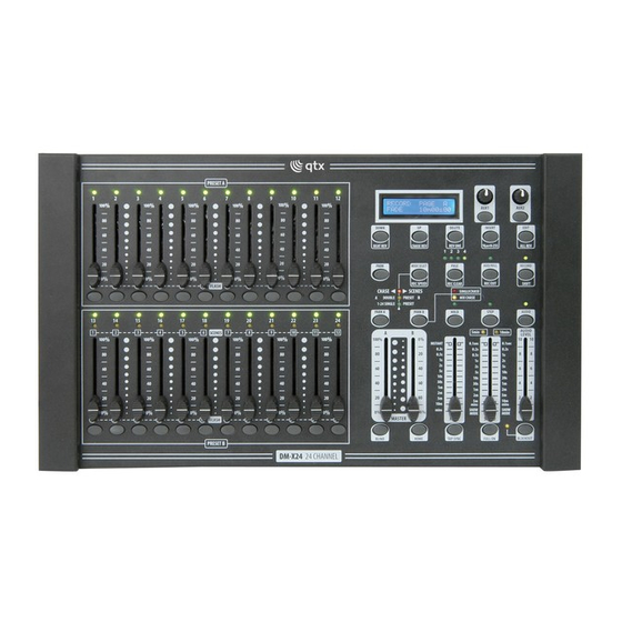
Page 5: Product Overview(Front)
DMX 512 CONTROLLER SERIES Product Overview(front) ITEM Button or Fader Function Channel Faders Indicates channels 1-12 Brings the relevant fader to 100% or DMX value of Channel Flash button Channel Faders Indicates channels 13-24 Scene Playback indicators Indicates that the scene is playing back Brings the relevant fader to 100% or DMX value of Channel Flash button Down functions to modify a scene in Edit mode, Beat... - Page 6 DMX 512 CONTROLLER SERIES Patchable; used to control a channel in 1 of 2 modes Aux 2 of operation Edit is used to activate Edit mode; All Rev is to Edit/All Rev reverse the chasing direction of all programes Record is used to activate Record mode or program a step;...
-
Page 7: Product Overview(Rear Panel)
DMX 512 CONTROLLER SERIES Product Overview(rear panel) DC INPUT DC INPUT MIDI MIDI DMX 512 OUTPUT DMX 512 OUTPUT SERIAL NO : SERIAL NO : POWER POWER LAMP LAMP AUDIO AUDIO REMOTE REMOTE 9V 1000mA 1000mA THRU 1=GROUND 2=DATA- 3=DATA+ DMX OUT DMX OUT DMX IN... -
Page 8: Operating Instructions
DMX 512 CONTROLLER SERIES Scenes are static lighting states. Sliders are also known as faders. Chases can also be called programs. A chase consists of scenes arranged one after another. Scanner refers to alighting instrument with a pan and tilt mirror, however DMX controllers can use this term to control any DMX-512 compatible device as a generic fixture. - Page 9 DMX 512 CONTROLLER SERIES 4.White holding Record, press the Flash button corresponding to the DMX output that you wish to assign the Fader to. 5.Repeat steps 2-3 as often as necessary 6.Press and hold Record & Rec Exit to exit the mode. F or exam ple: you wish to assign F ader # 1 to output to DM X channel # 5 1 .
-
Page 10: Programming
DMX 512 CONTROLLER SERIES 4.PROGRAMMING ENTERING PROGRAM MODE (RECORD ENABLE) 1. While holding the RECORD button, tap the Flash buttons 1-5-6-8 in sequence. 2. Release the RECORD button. The Record LED light up. CREASE A PROGRAM A s cene is a s tatic lighting s tate. Scenes are s tored in the tem porary m em ory, until they are trans ferred to one of the playback faders . -
Page 11: Delete A Step Or Steps
DMX 512 CONTROLLER SERIES 3) If you are not satisfied with the scene, you may press and hold the Record button & tap the Page/REC CLR button. All LEDs will flash, indicating the scenes have been cleared. Notes All scenes stored in the tem por ar y m em or y of the contr oller will be er ased by this pr ocess. This pr ocess will not affect the scenes already pr ogr am m ed into a Scene fader . -
Page 12: Playback
DMX 512 CONTROLLER SERIES 5.Playback This controller uses the Channel Faders and Channel Flash buttons for multiple uses. In this occurrence, Channel faders 13-24 are used playing back of scenes already recorded. This is only when the controller is the Chase scene mode. -
Page 13: Playing A Scene With The Speed Slider
DMX 512 CONTROLLER SERIES PLAYING A SCENE WI TH THE SPEED SLI DER Action 1) Select your Scene as described in the above sections 2)Move the Speed slider to SHOW MODE position (fully down). 3)Press and hold the Rec Speed button & tap the corresponding Flash button (13-24). The Scene tapped will no longer run with the standard beat 4)Now, you may move the Speed slider to select your desired speed. -
Page 14: Setting Midi In
DMX 512 CONTROLLER SERIES Setting MIDI IN Action 1) While holding down the RECORD button, simultaneously tap to Flash button #1 three times. The display reads MIDI CHANNEL IN to indicate channel setup is available. 2) Select the MIDI control channel (1-16)by tapping Flash button 1-16.The relevant channel LED lights indicating MIDI IN channel is est. -
Page 15: Sending Midi File Dump
DMX 512 CONTROLLER SERIES 8) While holding down RECORD, tap the REC EXIT button to exit MIDI setting. Notes: This is process of copying show to another same 48 CH dimmer console. This will not work with any other device. This process can take several minutes to complete. -
Page 16: Fixture Linking
DMX 512 CONTROLLER SERIES DMX fixtures are designed to receive data though a serial Daisy Chain. A Daisy Chain connection is where the DATA OUT of one fixture connects to the DATA IN of the next fiture.The order in which the fixtures are connected is not important and has no effect on how a controller communicates to each fixture. - Page 17 DMX 512 CONTROLLER SERIES Check users manual for speed Chase is too slow adjustment Check for power on mains. Device Check device S fuse.(intemal and/or Power external) Fixture Check DMX Dip switch setting for Correct addreesing responding Check DMX cables Check polarity switch settings Make sure you have the correct Fixture is on but...
-
Page 18: Dmx Dipswitch Quick Reference Chart
DMX 512 CONTROLLER SERIES DMX Dipswitch Quick Reference Chart DMX Address Quick Reference Chart DMX Address Quick Reference Chart Dip Switch Position DMX DIP SWITCH SET 0=OFF 1=ON X=OFF or ON 128 160 192 224 256 288 320 352 384 416 448 480 129 161 193 225 257 289 321 353 385 417 449 481 130 162 194 226 258 290 322 354 386 418 450 482 131 163 195 227 259 291 323 355 387 419 451 483... -
Page 19: Technical Specifications
DMX 512 CONTROLLER SERIES Technical Specifications WEIGHT & DIMENSIONS Length (485 mm) Width (290 mm) Height (98 mm) Weight (5 kg) POWER Operating DC 9V 1000ma 100-240v autos witching Adapter 2-pin Edison THERMAL 104 F(40 ) Maximum ambient temperature CONTROL &PROGRAMMING 3-pin DMX: Locking 3-pin XLR female socket Data output... -
Page 20: Qu Ic K Op Er At Io N
DMX 512 CONTROLLER SERIES Appendix: Quick operation Manual operation 1) Connect to power, Press BLACK OUT and it Os yellow LED light OF 2) Move sliders of MASTER A and FADE to top. 3) Use MODE SELECT to select 1-24 SINGLE mode 4) Move sliders to change DMX value to control lighting fixture.
Need help?
Do you have a question about the DM-X24 and is the answer not in the manual?
Questions and answers