Table of Contents
Advertisement
Quick Links
Advertisement
Table of Contents

Related Manuals for BobsCNC REVOLUTION


Summary of Contents for BobsCNC REVOLUTION
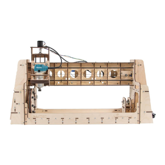
- Page 1 REVOLUTIO N Rotating Axis CNC Router Assembly Manual Rev. 2.5...
- Page 2 Welcome to the Family! We’re excited that you purchased the Revolution CNC Router Kit from BobsCNC. This manual was written to give you step-by-step instructions to ensure your success in assembling the Revolution CNC Router and provides all the information you need to get your machine up and running.
-
Page 3: Table Of Contents
Safety Precautions and Warnings ......................6 Getting Started ............................7 Required Tools: ....................................7 To Operate the REVOLUTION Rotating Axis Router, you need will need: ..............7 Assembly Recommendations: ........................8 Z Spindle Mount Assembly: ........................9 Required Wood Components ..............................9 Required Hardware .................................. - Page 4 Installing the Controller, the X Axis Home Switch, and the X and A Axis Stepper Motors ......113 Completed Views ........................... 122 Tramming .............................. 145 Congratulations! You Just Completed the Assembly of Your Revolution......... 148 Appendix ..............................149 Revolution Firmware Values ..............................149...
-
Page 5: Revolution Specifications
REVOLUTION Specifications Laser cut 6mm Baltic Birch Frame components. Fully Engineered Frame with rigid Box and Beam Gantry. Fully supported 5/16-inch stress proof steel Rails with SG20U Bearings. GT2 Belt Drive on X and A axes. Longworth Self Centering Chuck 2 mm pitch, 4 start Acme Threaded Rod on Z axis. -
Page 6: Information/Warning Boxes
Safety must be your First Priority. Always wear proper protective equipment and use "safety sense" when assembling and operating your Revolution CNC Router. Information/Warning Boxes CAUTION Indicates a possible risk of injury that can result from failure to follow this... -
Page 7: Safety Precautions And Warnings
Safety Precautions and Warnings The Revolution Rotating Axis CNC Router has a 110vac Power Supply and uses bits that spin up to 30,000 rpm with cutting edges that are sharp and hazardous. The operator must understand the potential hazards and is responsible to take appropriate safety precautions before operating the Router. -
Page 8: Getting Started
LOCTITE 242™ thread lock (fingernail polish can be used as a substitute). Set of Metric Sockets and SAE Wrenches. Set of Metric and SAE Long Reach Allen Wrenches. To Operate the REVOLUTION Rotating Axis Router, you need will need: Computer with control software for GRBL. Materials for Projects. -
Page 9: Assembly Recommendations
Assembly Recommendations: Use a large, flat, clean work surface for assembling your REVOLUTION. All Screws (unless noted) should be installed snug, then rotated 1-2 ½ turns. Apply LOCTITE 242 to all M4 Machine Screws that are used to secure ™... -
Page 10: Z Spindle Mount Assembly
Z Spindle Mount Assembly: Required Wood Components Z Frame Mount Support Z Frame Support Z Frame Z Spindle Bottom Mount... - Page 11 Z Spindle Interlock Bottom Z Spindle Interlock Top Z Spindle Top Mount Z Spindle Support...
-
Page 12: Required Hardware
Required Hardware Part # Description Photo Acme Block Nut 8“ Zip Tie M6 x 30 Machine Screws M6 Locknuts Eccentric Spacer Eccentric Washer Bearing Fender Washer SG20U Bearings M4 x 30 Machine Screws M4 x 16 Screws M4 Nuts M4 Lock Nuts... - Page 13 Illustrated Step by Step Instructions The Z Carriage Assembly holds the Router securely in a carriage that travels up and down the Z-axis on a set of Rails. These first steps will show you how to build the Spindle (Router) Mount. NOTE: The Z Frame has alignment marks that are used to snug the SG20U Bearings to the Rails and later to tram the Router.
- Page 14 Step 2 Loosely attach Spindle Interlock Bottom (Z5) to the Z Frame Assembly with two M4 x 16 Machine Screws and Nuts as shown. Do not tighten the Machine Screws and Nuts or use LOCKTITE. They will be tightened in a later step after the Router has been mounted.
- Page 15 Step 4 Attach Spindle Top (Z7) to the Z Frame Assembly with two M4 x 16 Machine Screws and Nuts as shown. Do not tighten the Machine Screws and Nuts at this stage. They will be tightened in a later step after the Router has been mounted. The Interlock Bottom and Top must be able to move slightly from front to back, this allowance will make installing the Router easier.
- Page 16 Step 6 Attach the Z Frame Support (Z2) to the Spindle Assembly with four M4 x 16 Machine Screws and Nuts as shown. Step 7 Fit the tabs on the Acme Block Nut into the slots on the back side of the Frame Assembly as shown. The ACME Block Nut tabs are designed to be a snug fit.
- Page 17 Step 8 Attach the second Frame Support (Z2) to the Spindle Top Plate Assembly with four M4 x 16 Machine Screws and Nuts as shown. Be careful to keep the Acme Block Nut securely in place. Step 9 Wrap an 8” Zip Tie around the Frame Supports as shown. Make sure the Zip Tie Lock is positioned on the Router side of the Assembly.
- Page 18 Test fit the Router in the Support Assembly as shown. This will help align the interlocking center pieces prior to final assembly and tightening. Remove the Router after dry fitting is completed. Video Link: https://www.youtube.com/watch?v=SkQ55V6ymEs&t=69s...
- Page 19 Step 10 Attach four SG20U Bearing Assemblies to the Z Frame. Loosely tighten the Nuts. These will be adjusted and tightened at a later step. When putting the Bearing Assembly together, make sure the hub on the Bearing faces the wood.
- Page 20 Prior to putting the Bearing Assembly together mark the point of the inboard edge of the Eccentric Adjustment Spacer using a permanent marker as shown below. This mark will help orient the Nut for tramming. Mark this inboard point...
- Page 22 Step 11 Attach the two (Z1) Frame Mount Supports to the (Z8) Spindle Support and secure with two M4 x 16 Machine Screws and Nuts. Step 12 Attach the Spindle Support Assembly to the Z-Frame Assembly with six M4 x 16 Machine Screws and Nuts as shown.
- Page 23 The finished Z Assembly should look like this:...
- Page 24 X Carriage Assembly Required Wood Components Part # Description Photo Z Stepper Motor Mount Rail Top Support Bearing Retainer Plate Carriage Frame Y Carriage Side Support Belt Retainer...
- Page 25 Z Rail Stop Carriage Bottom Support Rail Support Required Hardware Part # Description Photo Bearing Retainer Washer CB11 Stepper Motor Aluminum Coupler SG20U Bearing...
- Page 26 ACME Rod Small Shim Washer M6 x 30 Machine Screw M6 Locknut Eccentric Spacer Eccentric Washer Bearing Fender Washer M4 Lock Nut M4 x 16 Machine Screw M4 Nut 626-2RS Bearing 6mm Split Locking Collar Stress Proof Steel Z-Rail...
- Page 27 M2.5 x 16 Machine Screw M2.5 Lock Nut CB13 Home Switch M3 x 10 Machine Screw Small Zip Ties...
- Page 28 Illustrated Step by Step Instructions Step 1 Attach the Belt Retainer (XR6) to the front side of the Y Carriage Frame (XR4) and secure with four M4 x 16 Machine Screws and Lock Nuts as shown below. Make sure the ‘UP’ mark is visible and oriented toward the top of the Y Carriage Frame (NOTE: The Eccentric Bearing adjustment marks are on the opposite side of the X Carriage Frame as shown).
- Page 29 Step 2 Attach the SG20U Bearing Assembly. Attach and tighten the two upper SG20U Bearing Assemblies to the Y Carriage Assembly as shown. NOTE: The assembly order for the Upper Bearing: Machine Screw, SG20U Bearing (with hub facing toward the Bearing Washer), Bearing Washer, Plywood, Bearing Washer secured with a Lock Nut.
- Page 30 Attach the two lower SG20U Bearing Assemblies to the X Carriage Assembly as shown. These will be tightened in a later step. NOTE: The assembly order for the Lower Bearing: Machine Screw, SG20U Bearing (hub facing toward the Bearing Washer), Bearing Washer, Plywood, Eccentric Washer, Eccentric Spacer, secured with Lower Bearing Assembly with Eccentric...
- Page 31 Step 3 Attach the Carriage Bottom support (XR8) to the X Frame Assembly with two M4 x 16 Machine Screws and Nuts as shown. Step 4 Attach one Rail Support (XR9) to the X Frame Assembly with three M4 x 16 Machine Screws and Nuts as shown...
- Page 32 Step 5 Attach the second Rail Support (XR9) to the X Frame Assembly with three M4 x 16 Machine Screws and Nuts as shown. Step 6 Attach the Rail Top Support (XR2) to the X Frame Assembly with two M4 x 16 Machine Screws and Nuts as shown.
- Page 33 Step 7 Attach the Z Rail Stop (XR7) to the X Frame Assembly with two M4 x 16 Machine Screws and Lock Nuts as shown. Step 8 Attach one X Carriage Side Support (X5) to the Y Frame Assembly with seven M4 x 16 Machine Screws and Nuts as shown.
- Page 34 Step 9 Repeat for the other side. Attach one X Carriage Side Support (X5) to the Y Frame Assembly with seven M4 x 16 Machine Screws and Nuts as shown. Completed X Carriage Assembly...
- Page 35 X and Z Carriage Assembly Illustrated Step by Step Instructions WARNING Prior to installing the Lower Rails, adjust the Eccentric Spacers so that the lower Bearing Assemblies are at their outboard position. Step 1 Lay the X Carriage Assembly with the Bearings facing down. Fit the Z Carriage Assembly into the X Carriage Assembly as shown.
- Page 36 Rotate each Rail as you guide them through each of the components. This will help them to slide smoothly into place. Step 2 Hold the Assemblies together and carefully insert a Short Rail through the Upper Rail Support, threading it behind the upper SG20U Bearing as shown.
- Page 37 Step 3 Repeat to install the second Rail. The finished Assembly should look like this. Step 4 Attach the Stepper Motor to the Z Stepper Motor Mount (XR1) using four M3 x 10 Machine Screws. Note: The Stepper Motor wires are facing towards the protrusion.
- Page 38 Step 5 Thread the Stepper Motor wiring harness through the Motor Mount as shown. Step 6 Slide the 626-2RS Bearing onto the shaft of the ACME Rod. Next, insert 2 Shim Washers and secure in place with the 6mm Split Locking Collar by holding the Locking Collar tightly against the Bearing, then tighten the Set Screw as shown.
- Page 39 Step 7 Insert the ACME Rod through the hole in the Rail Top Support and thread into the ACME Block Nut as shown. Step 8 Place the Bearing Retainer Plate (XR3) over the Bearing and secure in place with three M4 x 16 Machine Screws, Bearing Retainer Washers and Lock Nuts.
- Page 40 NOTE: Washers must be placed so that they cover the Outer Bearing Race to secure it in place as shown. Once installed, spin the ACME Rod to confirm the Washers do not interfere with the rotation of the Locking Nut. Bearing Outer Race...
- Page 41 Step 9 Slide the Aluminum Coupler over the shaft of the Stepper Motor. Make sure the Set Screw fits against the flat of the Stepper Motor Shaft. Gently snug the Set Screw to keep it from rotating off the flat but loose enough so that it can slide up and down.
- Page 42 Step 11 Attach the Z Carriage Home Switch in the upper left inside corner of the X-Carriage Assembly using two M 2.5 x 16 Machine Screws and Lock Nuts as shown. [Note: Do not overtighten the Screws]. Step 12 Route the Home Switch Wires as shown below.
- Page 43 Step 13 Secure the Z Axis Stepper Motor and Home Switch wires with two Zip Ties to the Stepper Motor Mount as shown.
- Page 44 Chuck Assembly: Required Wood Components Outer Chuck Plate Chuck Pulley Inner Chuck Plate...
- Page 45 Required Hardware M4 Lock Nut M4x40 Hex Cap Screw Bearing Retainer Washer Chuck Gripper M4x16 Machine Screw 12mm Chuck Shaft 12mm Chuck Flange Round Foam Tabs...
- Page 46 Illustrated Step by Step Instructions Step 1 Attach the 12mm Chuck Flange to the Inner Chuck Plate (L4) using four M4 x 16 Screws with Locking Nuts. NOTE: Before attaching the Flange, insert the two set screws. Make sure they do not protrude into the center to allow the insertion of the 12mm Chuck Shaft in a later step.
- Page 47 Step 2 Insert the 12mm Chuck Shaft through the back of the Inner Chuck Plate Assembly for alignment as shown. Step 3 Remove the paper covering one side of the eight Round Foam Pads and carefully adhere them to the circular marks located on the Chuck Pulley (L3).
- Page 48 Step 4 Remove the paper covering on the remaining side of the eight Round Foam Pads Orient the side with the exposed Pads to face the back of the Inner Chuck Plate Assembly. Slip the Chuck Pulley (L3) over the 12 mm Chuck Shaft. Slide the Plates together being careful to keep the helical cutouts of the Chuck Pulley and those on the Inner Chuck Plate perfectly aligned.
- Page 49 Step 5 Attach the Chuck Grippers and Outer Chuck Plate (L2) to the Chuck Assembly. Align the Outer Chuck Plate (L2) with the Chuck Assembly so the helical cutouts intersect as shown below and slide the Outer Chuck Plate (L2) onto the 12mm Chuck Shaft.
- Page 50 After placing a Bearing Retainer Washer on to the shaft of the M4 x 40 Hex Cap Screw, slide the Screw through the intersection of the helical grooves as shown below. The Chuck is designed to allow the two Chuck Plates to counter rotate.
- Page 51 NOTE: Each Chuck Gripper must be properly oriented to the surface of Large Hole the Inner Plate. The end with the larger opening and rounded edge must be installed facing the wood. The end with the small hole will be covered with the Bearing Retainer Washer.
- Page 52 With the shaft end flush with the front chuck surface, secure the chuck flange 4 machine screws. The Completed Assembly...
- Page 53 Tail Stock Assembly: Required Wood Components Tail Stock Side Plate Tail Stock Top Plate Tail Stock Bottom Plate Tail Stock Top Brace Tail Stock Bottom Brace Tail Stock Guide Tail Stock Tensioner Tail Stock Retainer...
- Page 54 Required Hardware Part # Description Photo 5/16 x 3 Hex Cap Screw 5/16 Nut M4 x 16 Machine Screw M4 Nut 12mm Pillow Block Bearing 12mm Live Center M6x20 Socket-head Screw M6 Locknut M4 Lock Nut...
- Page 55 Illustrated Step by Step Instructions Step 1 Securely set a 5/16 Nut in the hex shaped hole in the Tail Stock Nut Retainer (TS8). It will be necessary to use a hammer, hard mallet, or handpress to press fit the Nut into the Retainer. Step 2 Attach the Tail Stock Nut Retainer Assembly to the Tail Stock Bottom Plate (TS3) and secure with two M4 x 16 Screws and M4...
- Page 56 Step 3 Attach a Pillow Block Bearing to the Tail Stock Side Plate (TS1). A Pillow Block Bearing is designed to allow the bearing to swivel within the block making it self-centering. After sliding the 12mm Shaft through the first Bearing, the second Bearing can be rotated within its Block as needed to pass a shaft through two Bearings.
- Page 57 Holding the 12 mm Pillow Block Bearing in place turn the Tail Stock Side Plate over and insert the Socket-head Screws so that the Screw head rests against the wood. Do not tighten completely until the live center in place. This will aid in alignment of the pillow block bearings with the live center in a later step.
- Page 58 Step 5 Building the Tail Stock Tensioning Assembly Attach the two Tail Stock Guides (TS6) to the Tail Stock Side Plate Assembly and secure with two M4 x 16 Screws and Nuts.
- Page 59 Insert the tab of Tail Stock Bottom Brace (TS5) into the slot in the Tail Stock Assembly. Insert the Tail Stock Tensioner (TS7) into the slot in the Tail Stock Assembly, centering the hex shaped hole with the hole in top of the Brace as shown.
- Page 60 Insert the 5/16 x 3” Hex Cap Screw into the hex shaped hole. Holding the bolt in place with a piece of tape will aid in assemble in a later step. Insert the tabs of the Tail Stock Top Brace (TS4) into corresponding slots in the Tail Stock Assembly and secure with two M4 x 16 Screws and Nuts.
- Page 61 Align the tabs with the slots in the second Tail Stock Side Plate Assembly and secure them together with four M4 x 16 Screws and Nuts. Rotate the Tail Stock Assembly to align the tabs of the Tail Stock guides with the slots of the Tail Stock Top Plate (TS2).
- Page 62 Place the Tail Stock Guides through the Tail Stock Bottom Plate Assembly and insert so that the end of the 3” Screw can be threaded into the 5/16” nut. Use the sprocket shape of the Tail Stock Tensioner to tighten the Bottom Plate Assembly and complete the Tail Stock Tensioning Assembly.
- Page 63 Step 6 Insert the 12mm Live Center into the Chuck on the opposite side of where the Tail Stock Tensioner (TS7) protrudes out the furthest, as shown. Tighten the Set Screws to secure the Live Center.
- Page 64 Base Assembly: Required Wood Components Part Descripti Photo Base Frame Base Tail Stock Guide Front Base Support Rear Base Support Base Brace Base Corner Bracket...
- Page 65 Required Hardware Part # Description Photo M4 x 30 Machine Screws M4 x 16 Screws M4 Nuts Illustrated Step by Step Instructions Step 1 Lay the Base Tail Stock Guide (BA2) on the Base Frame (BA1) as shown...
- Page 66 Step 2 Holding the two pieces together with the Base Tail Stock Guide on the bottom, insert the tabs of a Base Brace (BA5) into the slots of the Base Frame (BA1) and loosely secure with two M4 x 30 Machine Screws and Nuts. Repeat with the remaining seven Base Braces (BA5).
- Page 67 Step 3 Attach the Front Brace Support (B3) to the Base Assembly using sixteen M4x 16 Screws and Nuts. Step 4 Attach the Rear Base Support (B4) to the Base Assembly using sixteen M4 x 16 Screws and Nuts. Note: When Both Sides are attached, fully tighten the M4 x 30 Screws and Nuts...
- Page 68 Both Sides Attached Bottom View Both Sides Attached Front View Step 5 Attach the two (B6) Base Corner Brackets to the Base Assembly using two M4 x 16 Screws and Nuts for each.
- Page 69 Gantry Assembly Required Wood Components Gantry Frame X Rail Support Controller Mount Back Brace Gantry Back Support Gantry Top/Bottom Brace GR11 X Stepper Motor Mount GR12 X Belt Idler Mount GR13 X Belt Tensioner...
- Page 70 Required Hardware Part # Description Photo M4 x 16 Machine Screws M4 Nuts Large 8” Zip Ties M5 x 30 Machine Screw M5 Nut M5 Lock Nuts Idler Fender Washer Flanged Bearing F625Z Bearing Retainer Washers...
- Page 71 Prior to putting the Gantry Assembly together, note that the four ½” (12mm) holes at the bottom of the Gantry Frame (GR1) must be oriented on the bottom of the Gantry Assembly. They provide access to adjust the X Carriage Bearings needed in a later step. Bearing Adjustment Access Holes...
- Page 72 Illustrated Step by Step Instructions Step 1 Align and insert the tabs of the seven Y Rail Supports (GR4) into the slots in the (GR1) Gantry Frame and secure with fourteen M4 x 16 Machine Screws and Nuts. Finished Assembly should look like this.
- Page 73 Step 2 Align and insert the tabs of the Gantry Frame Assembly into the slots in the Gantry Bottom Brace (GR9) and secure with fifteen M4 x 16 Machine Screws and Nuts as shown. Step 3 Align and insert the tabs of the Gantry Back Support (GR8) into the slots of the Gantry Frame Assembly and secure with two M4 x 16 Machine Screws and Nuts.
- Page 74 Step 4 Align and insert the tabs of the Controller Mount (GR5) into the slots of the Gantry Frame Assembly and secure with two M4 x 16 Machine Screws and Nuts as shown. These small holes must be positioned at the bottom to properly install the Controller Mount (GR5).
- Page 75 Step 5 Align and insert the tabs of the Gantry Frame Assembly into the slots of the Gantry Top Brace (GR9) and secure with twenty-one M4 x 16 Machine Screws and Nuts as shown. Step 6 Align and insert the tabs of the Back Brace (GR7) into the slots of the Gantry Frame Assembly and secure with three M4 x 16 Machine Screws and Nuts as shown.
- Page 76 Step 7 Build two Idler Bearing Sub-Assemblies. Slide two F625Z Flanged Bearings on a M5 x 30 Machine Screw as shown. NOTE: install the flanges of the Bearings so that each flange is oriented to the outside from the other as shown. Thread a M5 Nut onto the Machine Screw, snug against the Bearings as shown.
- Page 77 Slide an Idler Fender Washer onto the Machine Screw against the M5 Nut. Insert the Bearing Assembly through X Belt Idler Mount (GR12) and snug with an Idler Fender Washer and M5 Lock Nut as shown below. The idler should able to slide with in the slot.
- Page 78 Place a 1 ½” strip of painter tape on one side of the Y Belt Adjuster. Insert a M4 Nut and a Bearing Retainer Washer in the appropriate slots and cover with another length of tape. Insert the M5 Lock Nut into the hex shaped hole in the X Belt Adjuster (GR13).
- Page 79 Step 8 Align the Idler Adjustment Assembly into the slots of the Gantry Frame Assembly as shown. Secure the Adjustment Assembly in place with one M4 x 16 Machine Screw and Nut. In the photo below, the Bearing Adjustment Access Holes are oriented to the top to simplify installation.
- Page 80 Step 9 Align and insert the tabs of the X Stepper Motor Mount (GR11) into the slots of Gantry Frame Assembly and secure with one M4 x 16 Machine Screw and Nut. In the photo below, the Bearing Adjustment Access Holes are oriented to the bottom to simplify installation.
- Page 81 Attaching the Base and Gantry Assembly Required Wood Components Part # Description Photo A-Axis Stepper Motor Mount A-Axis Stepper Motor Support GR17 Left Gantry Side Dial Indicator...
- Page 82 GR18 Right Gantry Side GR20L Gantry Mid Vertical Support GR20R...
- Page 83 GR21 Gantry Back Vertical Support GR10 A-Axis Belt Tensioner GR14 Gantry Top Brace GR15 Gantry Mid Brace GR16 Gantry Bottom Brace...
- Page 84 GR19L Gantry Front Vertical Support GR19R Chuck Support Front Chuck Brace Rear Chuck Brace Required Hardware Part # Description Photo M4 x 16 Machine Screws M4 Nut Bearing Fender Washer 12mm Pillow Block Bearing M6x20 Socket-head Screw...
- Page 85 M6 Lock Nut ¼ - 20 X 2” Screw ¼ - 20 Wing Nut ¼ - 20 Nut ¾ Spacer...
- Page 86 Illustrated Step by Step Instructions Do not tighten completely until the live center in place. This will aid in alignment of the pillow block bearings with the Chuck Shaft in a later step. Step 1 Attach a 12mm Pillow Block Bearing to the Left Gantry Side (GR17) and secure with two M6 x 20 Socket Head Screws and Locking Nuts.
- Page 87 Step 2 Align and insert the tabs of the Gantry Frame Assembly into the slots of the left Gantry Side Assembly and secure with eleven M4 x 16 Machine Screws and Nuts. Left Side In this photo, the Base was set on end to make it easier to align the tabs in the Base Assembly with the Left Side of...
- Page 88 Step 3 Align and insert the tabs of the Gantry Frame Assembly into the slots of the Right Gantry Side Assembly and secure with seven M4 x 16 Machine Screws and Nuts.
- Page 89 Step 4 Align and insert the tabs of the Gantry Frame Assembly and base into the slots of the Right Gantry Side (GR18) and secure with eighteen M4 x 16 Machine Screws and Nuts. Photos below show both sides attached to the Gantry and Base Assemblies. Front View Back View...
- Page 90 Step 5 Attaching the Left Side Assembly Components. Attach the Rear Chuck Brace (L7) to the Gantry Mid Vertical Support (GR20L) and secure with one M4 x 16Screw and Nut.
- Page 91 Attach the Front Chuck Brace (L6) to the Gantry Front Vertical Support (GR19L) and secure with a M4 x 16 Screw and Nut.
- Page 92 Insert a 12mm Pillow Block Bearing to the (L5) Chuck Support and secure with two M6 x 20 Socket-head Screws and Lock Nuts. Note that the hub side of the Bearing is set so that it extends through the opening. The Screws are placed so that the Nuts are exposed on the side with the laser engraved outline.
- Page 93 Attach the Gantry Mid Support Assembly and Chuck Support Assembly together with two M4 x 16 Screws and Nuts. Connect the Gantry Mid Support Assembly to the Gantry Front Support Assembly and secure with two M4 x 16 Screws with Nuts. Connect the (GR14) Gantry Top Brace to the (GR21) Gantry Back Vertical Support and secure with...
- Page 94 M4 x 16 Screw and Nut. Align the tabs on the Side Support Assembly with the slots on the Left Side of the Revolution Assembly and secure with nineteen M4 x 16 Screws and Nuts.
- Page 95 Insert the tabs (GR16) Gantry Bottom Brace into the corresponding slots in the Assembly and secure with six M4 x 16 Screws and Nuts. Insert the tabs of the (GR15) Gantry Mid Brace into the corresponding slots in the Assembly and secure with six M4 x 16 Screws and Nuts.
- Page 96 Completed Left Side...
- Page 97 Step 6 Attach the Gantry Right Side Assembly Components. Insert the tab of the (GR14) Gantry Top Brace into the (GR20R) Gantry Mid Vertical Support and secure with one M4 x 16 Screw and Nut. Insert the tab of the Gantry Top Brace (GR14) into the slot of the Gantry Mid...
- Page 98 Align the tabs of the Right-Side Vertical Assembly to the slots of the Right-Side Assembly and secure with fourteen M4 x 16 Screws and Nuts. Align the tabs of the Gantry Front Vertical Support (GR19R) to the slots of the Gantry Right Side and secure with three M4 x 16 Screws and Nuts.
- Page 99 Insert the Gantry Bottom Brace (GR16) into the slots of the attached vertical supports and secure with six M4 x 16 Screws and Nuts. Insert the Gantry Mid Brace (GR15) into the slots of the attached vertical supports and secure with six M4 x 16 Screws and Nuts.
- Page 100 Completed Right Side...
- Page 101 Step 7 Attach A-Axis Stepper Motor Support Insert the tabs of the A Axis Stepper Motor Support (GR3) into the Left Frame Assembly slots and secure with two M4 x 16 Screws and Nuts. Left Side, Rear View of Revolution...
- Page 102 Repeat for the remaining A-Axis Stepper Motor Mount (GR3) and secure with two M4 x 16 Screws and Nuts as shown. Top and Bottom A-Axis Stepper Motor Supports Installed...
- Page 103 Step 8 Assemble the A-Axis Stepper Motor Mount Using the remaining previously built Idler Bearing Assembly (see pages 76-77) insert the Idler Bearing Assembly, with an Idler Fender Washer, into the A-Axis Stepper Motor Mount (GR2), install a Idler Fender Washer and secure with a M5 Lock Nut.
- Page 104 Insert a M6 x 20 Socket-head Screw through the hole below the Bearing as shown. The idler should be able to slide within the slotted hole. Hold the Socket-head Screw in place and turn the Motor Mount over as shown to place a Bearing Fender Washer over the Screw.
- Page 105 Insert the A-Axis Belt Tensioner (GR10) as shown. Note: The hex shaped hole in the Tensioner is designed to fit over the Idler Assembly Lock Nut Secure the Belt Tensioner (GR10) with a M6 Lock Nut. The idler should be able to slide within the slotted hole.
- Page 106 Insert the ¼ - 20 X 2-inch Screw as shown. Place the ¾” Spacer on the Screw and snug in place with a ¼-20 Nut.
- Page 107 Step 9 Align the slots of the A-Axis Stepper Motor Mount Assembly with the tabs of the Stepper Motor Support and secure with four M4 x 16 Screws and Nuts. Step 10 Insert the Dial Indicator(L8) on the Front Left of the Frame Assembly and secure with one M4 x 16 Screw as shown.
- Page 108 A Pillow Block Bearing is designed to allow the bearing to swivel within the block making it self-centering. After sliding the 12mm Shaft through the first Bearing the second Bearing can be rotated within its Block as needed to pass a shaft through two Bearings. Step 11 Slide the 12mm Stainless Steel Shaft of the Chuck Assembly through the two mounted Pillow Block Bearings.
- Page 109 Step 12 Adjust the Chuck Assembly so there is a 1/16” gap between the Inner Chuck Plate and the Dial Indicator (L8) and tighten the two Set Screws on each Pillow Block Bearing and the Set Screws on the Chuck Flange. Edge of Dial Indicator 1/16”...
- Page 110 Step 13 Insert the Tail Stock Bottom Plate Assembly into the Base Assembly and position the Plate so that it can move from end to end beneath the Base Frame. NOTE: The Nut Assembly is oriented toward the right end of the Base. Position the Nut so that it rests on a Base Brace.
- Page 111 In the photo above a ¼” thick piece of shim stock was inserted into the Live Center Assembly with one end positioned over the hex head of the 3” Screw. The shim was lifted to hold the hex head down. At the same time, the Tail Stock Top Plate and Bottom Plate are gently squeezed together to enable the end of the bolt to engage the Nut while the Tail Stock Tensioner was turned in a clockwise direction to tighten the Nut.
- Page 112 Final Assembly Required Wood Components X Rail Stop 21mm Pulley Gauge Belt Guard Required Hardware Part # Description Photo Small Zip Ties GT2 Open Loop Belt GT2 Closed Loop Belt Stress Proof Steel X Rail M3 x 10 Machine Screw...
- Page 113 M4 x 30 Machine Screw 1/4” x 20 Wing Nut M4 Nut M2.5 x 16 Machine Screw M2.5 Lock CB13 Home Switch CB12 Power Supply with cord CB16 Controller GT2 Pulley CB11 Stepper Motor...
- Page 114 Installing the Controller, and the X Axis Home Switch Home Switches are simple contact switches. They can create a transient voltage spike when opened or closed. Stepper Motors also generate electrical interference which can cause the Controller to act as if a Home Switch has been depressed.
- Page 115 Step 2 Before Attaching the X Axis Home Switch to the Gantry, carefully thread the DuPont connector through the square access hole located in the upper left corner of the Gantry Assembly as shown below. Thread the Home Switch Wire through the access hole in the top of the Side Assembly, across the interior of the Gantry and through the access hole in the top of the Gantry Back Brace.
- Page 116 Connect the 2 pin DuPont connector to the X- pin on the Arduino Controller as shown circled below. Step 3 Attach the X Axis Home Switch to the underside in upper left corner of the Gantry Assembly as shown and secure with M2.5x10 Machine Screws and Lock Nuts.
- Page 117 Installing the X and A Axes Stepper Motors: Step 1 Use the 21mm Belt Pulley Gauge (GA1) to install the Belt Pulley on both Stepper Motors. Make sure the legs of the Gauge are set flat on the Motor Housing as shown. Insert the Pulley onto the Motor shaft.
- Page 118 Step 2 Position the X Axis Stepper Motor through the rectangular opening in the left end of the Gantry Assembly. Make sure to the wires are oriented to the left side of the Motor toward the controller mount. Secure the Motor in place with four M3x10 Machine Screws.
- Page 119 Route the wire across the bottom of the Gantry Assembly through small hole in the bottom of the Gantry Back Brace and through the X Slot in the Controller Support as shown, Step 3 Connect the 4 pin Dupont connector to the X Driver on the Controller as shown.
- Page 120 Step 4 Position the A Axis Stepper Motor through the rectangular opening of the Left Side Assembly. Note: The Stepper Motor is oriented so that the wires are at the top to make it easy to route the wires up through the Side Assembly.
- Page 121 Step 5 Route the A Axis Stepper Motor wires up and through the Side Assembly and across the Gantry as shown. Secure the A and X Axes Stepper Motor wires together with Zip Ties, routing the A Axis wires through the hole in the bottom of the Gantry brace.
- Page 122 Step 6 Route the A Axis connector through the A opening in the Controller mount and connect the 4 pin Dupont Connector onto the pins of the A Axis Driver as shown. Step 7 Secure the bundled wires together with Zip Ties every four inches and secure the bundled wires to the Gantry Assembly as shown.
- Page 123 Installing the ZX Assembly Rotate each Rail as you guide them through each of the components. This will help them to slide smoothly into place. Step 1 Insert the upper X Axis Rail through the top hole in the Left Side panel.
- Page 124 Step 2 Cut the GT2 Open Loop Belt to 56 1/2 inches. Lay the Y Carriage Assembly on the Base Assembly and insert the ends of the X Axis Belt into the Belt Retainer, making certain the Belt is not twisted.
- Page 125 Carefully loop the Belt around the X Carriage Assembly, making sure the ends remain secure in the X Belt Retainer. Then hang the upper Bearings of the X Carriage Assembly onto the upper X Rail as shown, being careful to keep the Belt between the upper and lower Bearings.
- Page 126 With the Belt out of the way, insert the lower X Rail through the Gantry Side, through the lower Rail Supports, over the top of the lower SG20U Bearings, and across into the opposite Gantry Side.
- Page 127 Attach the Rail Stops to each end of the Gantry Side using two M4 x 30 Machine Screws and Nuts for each side as shown. Loop the G2 Belt over the Idler Pulley at the right end of the Gantry as shown. Make sure the Belt is not twisted and that the Belt teeth are oriented as shown.
- Page 128 Loop the other end of the Belt over the Belt Pulley as shown. Make sure the teeth in the Belt engage the teeth of the Belt Pulley. Step 3 Adjust the X Carriage Eccentric Spacers equally on both sides using the alignment marks to tighten Bearings against the Rail as shown.
- Page 129 Align the access hole in the Gantry with the Bearing Screw. Using a 10mm socket and a Phillips Screwdriver, tighten the Lock Nuts to secure the 4 Bearing positions. Step 1 Installing the Makita RT0701C Router. Insert the Router into the Holder and with downward pressure, gently twist the Router body until it is fully seated in place in the Holder.
- Page 130 The inner 4 screws will need to be tightened to clamp the router into the Z Mount. First, align each Screw with one of the elongated access holes in the back of the Gantry. Note: To align the access hole with the Phillips head Screws, it may be necessary to raise or lower the Z Carriage.
- Page 131 With the Gantry and X Carriage aligned correctly, tighten the four Screws in the Router Z Mount. Tighten the 2 M4 X 30 Machine Screws and Lock Nuts to clamp the lower Router Mount.
- Page 132 Lower the Z Router Assembly as low as possible. Secure the Router Cord to the X Carriage and Gantry. Use Zip Ties to secure the Router Power Cord as shown. Be careful to route the Cord without putting stress on the stress relief as shown. Route the plug down and through the access hole on the right side of the Gantry Back Side as shown, then through...
- Page 133 Facing the back of the Gantry, slide the X Carriage all the way to the right. Allow enough slack in the cord so the X Carriage can travel from the right side of the Gantry to the left without binding as shown. Cord length estimated from the right side.
- Page 134 Connect the Z Axis Home Switch wire to the Z+ terminal. Connect the Z Axis Stepper Motor wire to the Z+ terminal.
- Page 135 Final Wire Management. Zip Tie the Power Cord to the top of the Gantry as shown. Step 2 Tighten the X Belt Insert the M4 x 30 Machine Screw through the large hole in the X Rail Stop as shown. Thread the Screw into the Nut of the Y Adjuster Assembly.
- Page 136 Tighten the Screw on the Idler Pulley to secure Belt Tensioner as shown. Step 3 Installing and tightening the GT2 Closed Loop A Belt. Loop the belt around the Idler Pulley as shown. Loop the belt beneath the Idler bearing and over the top of the Chuck Pulley as shown.
- Page 137 Rotate the Chuck Assembly so that the Belt is surrounds the Pulley. Tighten the Belt by pushing the A Axis Belt Tensioner down which lowers the Idler Pulley down against the Belt as shown.
- Page 138 Use a Phillips screwdriver to tighten the Idler Pulley in place. Step 4 Install the Belt Guard (L1) and secure with ¼” x 20 Wingnut.
- Page 139 Step 5 Install the Power Supply on the end in the back right side of the Gantry and then lay it horizontally behind the Gantry Back Support as shown.
- Page 140 Step 5a Route the Power Cord through the lower hole in the Back Brace, then behind the Controller Mount and through the PWR access hole.
- Page 141 Step 5b Loosen the screws in the blue terminal on the UNO Controller. Insert the exposed end of the Red Wire into the + side of the terminal and securely tighten in place. Repeat to install the Black wire in the –...
- Page 142 Step 6 Route the USB Cord up and through the left Gantry side, through the Gantry Assembly and connect it to the Uno Controller as shown.
- Page 143 Completed Views Front View Back View...
- Page 144 Left Side Right Side...
- Page 145 Properly Wired Controller...
- Page 146 Live Center though the center of the Chuck as illustrated below. If the Spindle is not perpendicular, the Revolution can be trammed on the X Axis by adjusting the four Eccentric Adjustment Spacers on the Z Carriage.
- Page 147 Eccentric spacers on the left side should be rotated clockwise so that the SG20U is snug up against the Rail. Eccentric spacers on the right side should be rotated counterclockwise so that the SG20U is snug up against the Rail.
- Page 148 The Spindle (Router) can be trammed on the A Axis by placing shims behind the SG20U Bearing Fender Washer. Placing the shim on the top will tilt the axis clockwise. Placing the shim on the bottom will tilt the axis counterclockwise.
- Page 149 Congratulations! You Have Completed the Assembly of Your Revolution. Please review our Software Setup Guide for Software installation and setup and our Getting Started guide to help with your first project. Revolution Manuals and Documentation – BobsCNC...
- Page 150 Appendix Revolution Washer Dimensions Thickness Part number Description (min) Thickness (max) Eccentric Washer 0.453 0.750 0.059 0.063 Bearing Fender Washer 0.250 0.750 0.060 0.090 Idler Fender Washer 0.203 0.750 0.043 0.051 Bearing Retainer Washer 0.172 0.050 0.050 0.080 1/4 Shim Washer 0.256...
- Page 151 5 (homing pull-off, mm) 1000 Maximum spindle speed, RPM 0 Minimum spindle speed, RPM 0 Laser-mode enable, boolean $100 80 (x, step/mm) $101 80 (y, step/mm) $102 400 (z, step/mm) $110 10000 (x max rate, mm/min) $111 10000 (y max rate, mm/min) $112 2000 (z max rate, mm/min) $120...
Need help?
Do you have a question about the REVOLUTION and is the answer not in the manual?
Questions and answers