Table of Contents
Advertisement
Quick Links
,
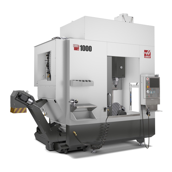
UMC-1000
Next Generation Control
Operator's Manual Supplement
96-8350
Revision A
December 2018
English
Original Instructions
Haas Automation Inc.
2800 Sturgis Road
Oxnard, CA 93030-8933
U.S.A. | HaasCNC.com
©
2018 Haas Automation, Inc. All Rights Reserved. Copy by Permission Only. Copyright Strictly Enforced.
Advertisement
Table of Contents

Related Manuals for Haas Automation UMC-1000

Summary of Contents for Haas Automation UMC-1000
- Page 1 Next Generation Control Operator’s Manual Supplement 96-8350 Revision A December 2018 English Original Instructions Haas Automation Inc. 2800 Sturgis Road Oxnard, CA 93030-8933 U.S.A. | HaasCNC.com © 2018 Haas Automation, Inc. All Rights Reserved. Copy by Permission Only. Copyright Strictly Enforced.
- Page 3 Haas Automation, Inc. No patent liability is assumed with respect to the use of the information contained herein. Moreover, because Haas Automation strives constantly to improve its high-quality products, the information contained in this manual is subject to change without notice.
- Page 4 This product uses Java Technology from Oracle Corporation and we request that you acknowledge that Oracle owns the Java Trademark and all Java related Trademarks and agree to comply with the trademark guidelines at www.oracle.com/us/legal/third-party-trademarks/index.html. Any further distribution of the Java programs (beyond this appliance/machine) is subject to a legally binding End User License Agreement with Oracle.
- Page 5 Covering Haas Automation, Inc. CNC Equipment Effective September 1, 2010 Haas Automation Inc. (“Haas” or “Manufacturer”) provides a limited warranty on all new mills, turning centers, and rotary machines (collectively, “CNC Machines”) and their components (except those listed below under Limits and Exclusions of Warranty) (“Components”) that are manufactured by Haas and sold by Haas or its authorized...
- Page 6 Limits and Exclusions of Warranty Components subject to wear during normal use and over time, including, but not limited to, paint, window finish and condition, light bulbs, seals, wipers, gaskets, chip removal system (e.g., augers, chip chutes), belts, filters, door rollers, tool changer fingers, etc., are excluded from this warranty.
- Page 7 Customer has accepted the limitations and restrictions set forth in this Certificate, including, but not limited to, the restriction on its right to recover damages, as part of its bargain with Manufacturer or its Authorized Representative. Customer realizes and acknowledges that the price of the Haas Products would be higher if Manufacturer were required to be responsible for damages and claims beyond the scope of this warranty.
- Page 8 Customer Advocate. Join Haas owners online and be a part of the greater CNC community at these sites: haasparts.com Your Source for Genuine Haas Parts www.facebook.com/HaasAutomationInc Haas Automation on Facebook www.twitter.com/Haas_Automation Follow us on Twitter www.linkedin.com/company/haas-automation Haas Automation on LinkedIn www.youtube.com/user/haasautomation...
- Page 9 Att: Customer Satisfaction Manager email: customerservice@HaasCNC.com Once you contact the Haas Automation Customer Service Center, we will make every effort to work directly with you and your HFO to quickly resolve your concerns. At Haas Automation, we know that a good Customer-Distributor-Manufacturer relationship will help ensure continued success for all concerned.
- Page 10 viii...
- Page 11 Product: Mill (Vertical and Horizontal)* *Including all options factory- or field-installed by a certified Haas Factory Outlet (HFO) Manufactured By: Haas Automation, Inc. 2800 Sturgis Road, Oxnard, CA 93030 805-278-1800 We declare, in sole responsibility, that the above-listed products, to which this declaration refers, comply with the regulations as outlined in the CE directive for Machining Centers: •...
- Page 12 USA: Haas Automation certifies this machine to be in compliance with the OSHA and ANSI design and manufacturing standards listed below. Operation of this machine will be compliant with the below-listed standards only as long as the owner and operator continue to follow the operation, maintenance, and training requirements of these standards.
- Page 13 User’s Operator Manual and other Online Resources This manual is the operation and programming manual that applies to all Haas Mills. An English language version of this manual is supplied to all customers and is marked "Original Instructions". For many other areas of the world, there is a translation of this manual marked "Translation of Original Instructions".
- Page 14 How to Use This Manual How to Use This Manual To get the maximum benefit of your new Haas machine, read this manual thoroughly and refer to it often. The content of this manual is also available on your machine control under the HELP function.
- Page 15 Text Conventions Used in this Manual Description Text Example G00 G90 G54 X0. Y0.; Code Block text gives program examples. [CYCLE START] A Control Button Reference gives the name of a Press control key or button that you are to press. A File Path describes a sequence of file system Service >...
- Page 16 How to Use This Manual...
-
Page 17: Table Of Contents
Overview....... . . 17 UMC-1000 Workstations ......17 Axis Definitions . - Page 18 Introduction ....... 45 UMC-1000 Maintenance Schedule ....45 More Information Online .
-
Page 19: Chapter 1 Safety
Cutting tools, workholding, workpiece and coolant are beyond the scope and control of Haas Automation, Inc. Each of these potential hazards associated with it (sharp edges, heavy lifting considerations, chemical composition, etc) and it is the responsibility of the user to take appropriate action (PPE, training, etc). -
Page 20: Summary Of Types Of Operation For Haas Automation Machine Tools
General Safety Notes 1.1.1 Summary of Types of Operation for Haas Automation Machine Tools Haas CNC Mills are intended for cutting and shaping of metals and other hard materials. They are general purpose in nature and a list of all of those materials and types of cutting would never be complete. - Page 21 Safety Adding lubricants • Adding lubricants for spindle and axes is required at regular intervals. These are often months or years in length. This is a normal operator function and is always done from a safe location outside of the work enclosure. Cleaning chips out of the machine •...
-
Page 22: Read Before Operating
General Safety Notes 1.1.2 Read Before Operating DANGER: Do not enter the machining area any time the machine is in motion, or at any time that machine motion is possible. Severe injury or death may result. Motion is possible when the power is on and the machine is not in [EMERGENCY STOP]. - Page 23 Safety Operation Safety: • Do not operate the machine unless the doors are closed and the door interlocks are functioning correctly. • Check for damaged parts and tools before you operate the machine. Any part or tool that is damaged should be properly repaired or replaced by authorized personnel. Do not operate the machine if any component does not appear to be functioning correctly.
- Page 24 General Safety Notes Periodic maintenance of machine safety features: • Inspect door interlock mechanism for proper fit and function. • Inspect safety windows and enclosure for damage or leaks. • Verify all enclosure panels are in place. Door Safety Interlock maintenance: •...
-
Page 25: Machine Environmental Limits
NOTE: Actual noise levels while cutting material are greatly affected by the user’s choice of material, cutting tools, speeds and feeds, workholding and other factors. These factors are application specific and are controlled by the user, not Haas Automation Inc. -
Page 26: Unattended Operation
Unattended Operation Unattended Operation Fully enclosed Haas CNC machines are designed to operate unattended; however, your machining process may not be safe to operate unmonitored. As it is the shop owner’s responsibility to set up the machine safely and use best practice machining techniques, it is also the owner’s responsibility to manage the progress of these methods. - Page 27 Safety Machine Function RUN Mode SETUP Mode Axis Jog using the RJH Handle Not allowed. Allowed. Axis Jog using the RJH shuttle Not allowed. Not allowed. knob Axis Rapid using Home G28 or Not allowed. Not allowed. Second Home Axis Zero Return Not allowed.
-
Page 28: Robot Cells
Door Rules - Run / Setup Mode Machine Function RUN Mode SETUP Mode Through Spindle Coolant (TSC) Not allowed. Not allowed. Tool Air Blast (TAB) On Not allowed. Not allowed. DANGER: Do not attempt to override safety features. Doing so makes the machine unsafe and voids the warranty. -
Page 29: Modifications To The Machine
Haas Automation, Inc. is not responsible for damage caused by modifications you make to your Haas machine(s) with parts or kits not manufactured or sold by Haas Automation, Inc. The use of such parts or kits may void your warranty. -
Page 30: Safety Decals
Safety Decals Safety Decals The Haas factory puts decals on your machine to quickly communicate possible hazards. If decals become damaged or worn, or if you need additional decals to emphasize a particular safety point, contact your Haas Factory Outlet (HFO). NOTE: Never alter or remove any safety decal or symbol. -
Page 31: Decal Symbols Reference
Safety 1.6.1 Decal Symbols Reference This section gives explanations and clarifications for the safety symbols you will see on your machine. T1.3: Hazard Symbols – Yellow Triangles Symbol Description Moving parts can entangle, trap, crush, and cut. Keep all parts of your body away from machine parts when they move, or whenever motion is possible. - Page 32 Safety Decals Symbol Description Long tools are dangerous, especially at spindle speeds higher than 5000 RPM. The tools can break and eject from the machine. Remember that machine enclosures are intended to stop coolant and chips. Enclosures may not stop broken tools or thrown parts. Always check your setup and tooling before you start machining.
- Page 33 Safety Symbol Description Do not attempt to load tools with the spindle dogs misaligned with the cutouts in the toolholder V-Flange. Do not machine flammable materials. Do not use flammable coolants. Flammable materials in particulate or vapor form can become explosive. The machine enclosure is not designed to contain explosions or extinguish fire.
- Page 34 Safety Decals T1.5: Recommended Action Symbols – Green Circles Symbol Description Keep the machine doors closed. Always wear safety glasses or goggles when you are near a machine. Airborne debris can cause eye damage. Always wear hearing protection when you are near a machine. Machine noise can exceed 70 dBA.
-
Page 35: Other Safety Information
Safety T1.6: Informational Symbols – Black Circles Symbol Description Maintain the recommended coolant concentration. A “lean” coolant mixture (less concentrated than recommended) may not effectively prevent machine components from rusting. A “rich” coolant mixture (more concentrated than recommended) wastes coolant concentrate without further benefit over the recommended concentration. - Page 36 Safety Decals...
-
Page 37: Chapter 2 Introduction
You can find specific details about the UMC family, including information that is beyond the scope of this document, at www.HaasCNC.com. UMC-1000 Workstations F2.1: This diagram illustrates the UMC-1000 three operator zones. • A: Operator Station. • B:Check and Maintain Chip Conveyor. -
Page 38: Axis Definitions
Axis Definitions Axis Definitions F2.2: This diagram illustrates the (5) axes available on the UMC-1000. -35° +110° UMC-1000 Specifications T2.1: UMC-1000 Specifications Travels S.A.E Metric X Axis 40" 1016 mm Y Axis 25" 635 mm Z Axis 25" 635 mm... - Page 39 Spindle Nose to Table (~ min.) 4" 102 mm Spindle Nose to Table (~ max.) 29" 737 mm For detailed machine dimensions, including work envelope information, refer to the UMC-1000 Machine Layout Drawing on www.haascnc.com. Table Platter Diameter 25" 635 mm T-Slot Width 5/8"...
- Page 40 UMC-1000 Specifications...
-
Page 41: Chapter 3 Wireless Intuitive Probing System (Wips)
Normally, you use WIPS to set tool and work offsets, but the UMC-1000 includes a master gauge length tool in case you need to set offsets manually (if, for example, a probe stylus breaks or the batteries lose power). -
Page 42: Machine Rotary Zero Point (Mrzp) Offsets
The Machine Rotary Zero Point (MRZP) Offsets are set at the factory. 3.3.1 Check MRZP Offsets with VPS The MRZP offsets can change over time. To make sure the UMC-1000, MRZP Offsets are correct do the following: Place the tooling ball in the center of the X axis. - Page 43 Wireless Intuitive Probing System (WIPS) F3.1: Calibration Tooling Ball Place the work probe in the spindle. Position the work probe over the tooling ball. Navigate to [EDIT]>VPS>PROBING>CALIBRATION>MRZP and select B-Axis Tilt C-Axis Rotary Finish Set and press [ENTER]. Type gage ball diameter and press [ENTER]. Follow the prompts to generate the probe program.
- Page 44 Machine Rotary Zero Point (MRZP) Offsets...
-
Page 45: Chapter 4 G234 - Tool Center Point Control (Tcpc)
G234 - Tool Center Point Control (TCPC) Chapter 4: G234 - Tool Center Point Control (TCPC) G234 - Tool Center Point Control (TCPC) (Group 08) G234 Tool Center Point Control (TCPC) is a software feature in the Haas CNC control that allows a machine to correctly run a contouring 4- or 5-axis program when the workpiece is not located in the exact location specified by a CAM-generated program. - Page 46 G234 - Tool Center Point Control (TCPC) (Group 08) F4.1: Location of Workpiece Defined by G54 X0, Y0, Z0 (G54) X0, Y-1., Z0 In Figure F4.2, the B and C Axes have been rotated 15 degrees each. To create the same edge, the machine needs to make an interpolated move with the X, Y, and Z Axes.
- Page 47 G234 - Tool Center Point Control (TCPC) F4.3: G234 (TCPC) On and the B and C Axes Rotated X0, Y0, Z0 X0, Y-1., Z0 G234 Program Example O00003 (TCPC SAMPLE) G00 G17 G40 G80 G90 G94 G98 G53 Z0. T1 M06 G00 G90 G54 B47.137 C116.354 (POSITION ROTARY AXES) G00 G90 X-0.9762 Y1.9704 S10000 M03 (POSITION LINEAR AXES) G234 H01 Z1.0907 (TCPC ON WITH LENGTH OFFSET 1, APPROACH IN...
- Page 48 G234 - Tool Center Point Control (TCPC) (Group 08) G01 X-0.5688 Y1.1481 Z0.2391 F40. X-0.4386 Y0.8854 Z-0.033 X-0.3085 Y0.6227 Z-0.3051 X-0.307 Y0.6189 Z-0.3009 B46.784 C116.382 X-0.3055 Y0.6152 Z-0.2966 B46.43 C116.411 X-0.304 Y0.6114 Z-0.2924 B46.076 C116.44 X-0.6202 Y0.5827 Z-0.5321 B63.846 C136.786 X-0.6194 Y0.5798 Z-0.5271 B63.504 C136.891 X-0.8807 Y0.8245 Z-0.3486 X-1.1421 Y1.0691 Z-0.1701...
- Page 49 G234 - Tool Center Point Control (TCPC) G234 Programmer’s Notes These key presses and program codes cancel G234: • [EMERGENCY STOP] • [RESET] • [HANDLE JOG] [LIST PROGRAM] • • M02 – Program End • M30 – Program End and Reset •...
- Page 50 G234 - Tool Center Point Control (TCPC) (Group 08)
-
Page 51: Chapter 5 G254 - Dynamic Work Offset (Dwo)
G254 - Dynamic Work Offset (DWO) Chapter 5: G254 - Dynamic Work Offset (DWO) G254 - Dynamic Work Offset (DWO) (Group 23) G254 Dynamic Work Offset (DWO) is similar to TCPC, except that it is designed for use with 3+1 or 3+2 positioning, not for simultaneous 4- or 5-axis machining. If the program does not make use of the tilt and rotary Axes, there is no need to use DWO. - Page 52 G254 - Dynamic Work Offset (DWO) (Group 23) NOTE: For clarity, the illustrations in this section do not depict workholding. The block in the figure below was programmed in the CAM system with the top center hole located at the center of the pallet and defined as X0, Y0, Z0. F5.1: Original Programmed Position X0, Y0, Z0...
- Page 53 G254 - Dynamic Work Offset (DWO) F5.3: Center with DWO On X0, Y0, Z0 G254 Program Example O00004 (DWO SAMPLE) ; G20 ; G00 G17 G40 G80 G90 G94 G98 ; G53 Z0. ; T1 M06 ; G00 G90 G54 X0. Y0. B0. C0. (G54 is the active work offset for) ;...
- Page 54 G254 - Dynamic Work Offset (DWO) (Group 23) G254 Programmer’s Notes These key presses and program codes will cancel G254: [EMERGENCY STOP] • • [RESET] • [HANDLE JOG] • [LIST PROGRAM] • G255 – Cancel DWO • M02 – Program End •...
-
Page 55: Chapter 6 Setting Work And Tool Offsets
Setting Work and Tool Offsets Chapter 6: Setting Work and Tool Offsets Set the B-Axis Work Offset If the fixture or workpiece requires you to adjust the B Axis to achieve the proper alignment for machining, use this procedure to adjust and record the B-Axis work offset. CAUTION: Do not use a B-Axis offset if your program uses Dynamic Work Offsets (G254). -
Page 56: Set The X-, Y-, And Z-Axis Work Offsets Manually
Set the X-, Y-, and Z-Axis Work Offsets Manually F6.1: Setting the C-Axis Workpiece Orientation Place the workpiece on the platter (workholding not shown). Adjust the C Axis until the workpiece is positioned to the same orientation established in the program. Typically, a reference feature on the fixture or workpiece is parallel to the X or Y Axis. - Page 57 Setting Work and Tool Offsets Jog the X and Y Axes to the zero position established in the program. F6.2: UMC-1000 X- and Y-Axis Zero Position Navigate to [OFFSET]>Work. Scroll to the work offset value used in the program (G54 in this example).
- Page 58 Set the X-, Y-, and Z-Axis Work Offsets Manually F6.4: Example Tool Set Plane (Top of the Part) Load the master gage tool included with WIPS into the spindle. F6.5: Master Gage Tool Make sure that the B and C Axes are at the same work zero point set earlier. (G00 G90 G54 B0 C0)
- Page 59 Setting Work and Tool Offsets Select the Z AXIS column of your work coordinate offset. Jog the Z Axis to the tool set plane. Make sure that the end of the gage tool you are using just touches the tool set plane. You will touch-off all of your tools on this surface.
-
Page 60: Set The X-, Y-, And Z-Axis Work Offsets With Wips
If you are not using the WIPS system, go to the Set the X-, Y-, and Z-Axis Work Offsets Manually section, starting on page 37. NOTE: Make sure that the tool setting probe and the work probe are calibrated. Refer to the Haas WIPS manual (96-10002) for the calibration procedure. F6.7: UMC-1000 Work Offset with WIPS... - Page 61 Setting Work and Tool Offsets F6.8: UMC Z-Axis Work Zero Offset Start 0.25" (6 mm) Load the work probe into the spindle. Make sure that the B and C Axes are at the same work zero point set earlier. (G00 G90 G54 B0 C0). Refer to the Set the B-Axis Work Offset and Set the C-Axis Work Offset sections if these values are not correct.
- Page 62 Set the X-, Y-, and Z-Axis Work Offsets with WIPS F6.9: VPS 11. Single Surface Probe Type -.5 (or -12 if the control is set to metric measurements), and then press [ENTER]. Press [CYCLE START]. The probe measures the distance to the top of the part and records the value in the Z Axis column work offset for G54.
-
Page 63: Chapter 7 Rotary Unwind And Setting 247
If Setting 247 is ON, the axes move simultaneously. This may cause collisions between the tool and the workpiece, due to B- and C-Axis rotations. It is strongly recommended that this setting remain OFF on the UMC-1000, due to the high potential for collisions. - Page 64 247 - Simultaneous XYZ Motion in Tool Change...
-
Page 65: Chapter 8 Maintenance
The most common maintenance tasks are simple and you can do them yourself. You can also ask your HFO about their comprehensive preventive maintenance program for complex maintenance tasks. UMC-1000 Maintenance Schedule T8.1: Maintenance Schedule Table... - Page 66 UMC-1000 Maintenance Schedule Maintenance Item Interval Inspect way covers and lubricate. Monthly Minimum Quantity Lubrication Clean the filter inside the oil reservoir. Annually Oil Skimmer Inspect the oil skimmer pickup tube. Six Months Pneumatics Inspect the spindle air regulator pressure.
- Page 67 Maintenance Maintenance Item Interval Inspect the coolant concentration. Weekly Completely clean the coolant tank and replace Six Months the coolant. Clean the standard coolant filter. Six Months Verify the coolant refill is operating correctly. Six Months Spindle Clean and lubricate the spindle taper. As required.
-
Page 68: More Information Online
More Information Online More Information Online For updated and supplemental information, including tips, tricks, maintenance procedures, and more, visit the Haas Service page at www.HaasCNC.com. You can also scan the code below with your mobile device to go directly to the Haas Service page:... -
Page 69: Index
Index ........air requirement safety ..........decals ........door interlock ..............c-axis rotary unwind during operation ................. coolant capacity electrical ........glass window ........introduction ............. dynamic work offset (G254) maintenance ......part loading/unloading ........robot cells linear axis (x,y,z) offsets safety decals ........
Need help?
Do you have a question about the UMC-1000 and is the answer not in the manual?
Questions and answers