Advertisement
Quick Links
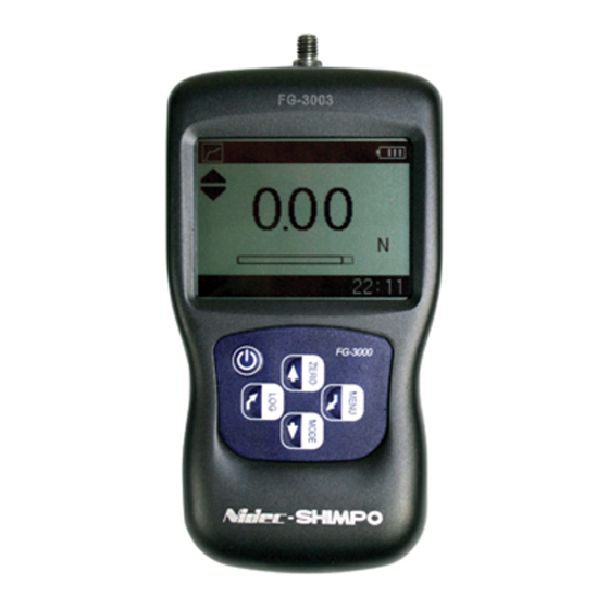
FG-3000 Digital Force Gauge
Operation Manual
Operators should wear protection such as a mask and gloves in case
pieces or components break away from the unit under test.
Whether the unit is ON or OFF, DO NOT exceed the capacity of the
gauge. NEVER exceed 150% of the rated capacity, or the load cell will
be damaged. At 110% of the rated capacity, the display will flash a
warning.
When mounting FG-3000 Series Digital Force Gauges, use M4 mount-
ing screws with a maximum insertion depth of 7 mm into the gauge.
Hand tighten mounting screws, DO NOT use tools. Do not use damaged
clamp.
Measure in line tension and compression forces only. DO NOT attempt
to measure forces at an angle to the measuring shaft – damage to load
cell and/or shaft may result.
Do not attempt to repair or alter this instrument. Warranty will be voided
and damage to the unit may result.
Use and store within the stated temperature and humidity ranges, or
damage and failure may result.
When using adapter measuring heads, do not use tools. Hand tighten
only.
Th e n ew F G- 30 0 0 S e ri e s d i gi ta l f o rc e ga uge s are th e
ch oic e fo r s imp le , c o st-e f f ec t iv e t e n s i on a nd co mp re s -
sion t es ting .Co mb ining o n e o f th e m o s t c o mp a c t h o u s -
ings, ye t m a int a ini ng a la r ge b a c k-l i t L C D, t he se u n i ts
wer e de s i gn ed t o f it p e r f e c t l y i n t h e h a nd f or eas e o f
use. T he m ult i- la ng ua g e F G - 30 0 0' s p r o v i d e m en u p ro -
gr amm ing fo r int uitiv e s e t- up o f t he i ns t r um en t to y o u r
desired r e qu ire m ents . Th re e mo d e s of op e r a ti o n a re
sel ecta bl e: Tr a c k mo d e d i s p l a y s l i v e r e a d in gs , Peak
mod e r eco r ds th e m a x im u m r ea d i ng s e n s ed d u ri n g th e
test, a nd Pr e - se t m od e w hi ch a c t iv a te s u s e r def i n ed
high an d l o w l imi t s e t p oi n ts . T h e p r o gr a mm ab l e l i m -
its p ro vide a q uic k v is u al a n d a u d ib l e i nd i c ati o n i f a
test p a s s es o r fa ils . In a d d it i on , a c o mp a r a to r o u tpu t
enab les i nte g r a tio n of th e in s t ru me nt in t o yo u r qu al -
ity sys te m f o r rep etit iv e te s t in g s u c h a s o n p r od u c ti o n
li n es.
Th e d is pla y gr a phi cs f a ci l i ta t e u s e r c o mp re h e n si o n
and o per a tio n. A n a n a l og b a r gr a p h p r o v i d es persp ec -
tiv e of cur re n t re a d i ng in c o mp a r is on t o t he f u l l sc al e
range . Pa s s /Fa il i cons p r o v i d e a n i n s t a nt r e s p o n s e o f
the t est in g o utc o m e w hil e a s t o ra g e s y m b o l a c k n o wl -
ed ges whe n a re a d in g is l o gge d . A me nu -s el e c tabl e
disp la y o rie nta ti o n st re a m l in e s s w it c hi ng f ro m pu s h to
pu ll tes ting fo r po rta b le o r t e s t s ta n d a p p l i c a ti o n s.
4
3
5
6
7
10
SPECIFICATIONS
Accuracy: ± 0.3% F.S.
Selectable Units: N, kgf, ozf, and lbf. (Depending on Range)
Overload Capacity: 150% of F.S. (LCD flashes beyond 110% of
F.S.)
Measurement Method: Peak, Track, Preset
Data Sampling Rate: 1000 Hz
Display: 160*128 dot matrix LCD with Backlight
Display Update Rate: 10 times/second
Resolution: (See chart)
Memory: 500 data
Set Point: Programmable high and low limits in Preset Mode
Battery Indicator: Display flashes battery icon when battery is
low
Power: 3.6VDC 800mAH Ni-MH rechargeable batteries
Battery Life: Approximately 16 hours continuous use per full
charge
Charger / Adaptor: Universal USB/BM charger, Input: 110 ~
240VAC
Temperature Effects: <0.054% per °F (0.03% FS per °C)
Outputs: USB, RS-232; High & Low Limit NPN's
Operating Temperature: 14 to 104°F (-10 to 40°C)
Storage Relative Humidity: 20 to 80%
Housing: Aluminum
Storage Temperature: -4 to 122°F (-20 to 50°C)
Oper. Relative Humidity: 5 to 95%
Dimensions: 5.5 x 2.8 x 1.4" (140 x 71 x 35.5 mm)
Product Weight: 0.9 lb (0.4 kg)
Package Weight: 2.25 lb (1 kg)
Warranty: 1 year
Certification: CE
Included Accessories: AC Adaptor/Charger, USB cable, cali-
bration cert., 6 attachments: hook, flat tip, conical tip, chisel tip,
notched tip, extension shaft.
LCD Screen
1
1. Battery icon: Battery level or charging status. Flashes when
2. OK/OV Indicator:
2
3. Force icon: Indicates force direction.
9
4. Test mode icon: Three measurement modes: Track, Peak
5. Current meaured value
6. Analog bar: Indicates current position within full scale. When
8
7. Storage icon: Indicates data is being saved.
8. System time
9. Units Indicator: Selected engineering unit.
10. Data Transmission icon
gauge needs to be recharged.
Measured value between low limit
and upper limit;
Value over upper limit
Value between lower limit and 75% of lower limit
Compression
and Preset
the bar enters the area enclosed by the dotted line, it means
full scale capacity is exceeded and overload.
Tension
Advertisement

Related Manuals for Nidec-Shimpo FG-3006


Summary of Contents for Nidec-Shimpo FG-3006
- Page 1 FG-3000 Digital Force Gauge Operation Manual Operators should wear protection such as a mask and gloves in case pieces or components break away from the unit under test. Whether the unit is ON or OFF, DO NOT exceed the capacity of the gauge.
- Page 2 1. OPERATION 2. PREPARATION 1.1 Key Functions All keys are capacitive touch. 2.1 Confirm the model This series force gauge has 5 ranges available, each model corre- ON/OFF: Push for 1 second to power On or Off sponding to the capacity and resolution shown on the last page of this manual.
-
Page 3: Saving The Measured Value
3.3 Select Test Mode 4.1 Memory The FG-3000 has 3 types of Test Modes. Track: The real time measuring mode. Under this mode, press the ZERO key to tare any initial reading being displayed. Peak: In Peak mode, the maximum force will be recorded and displayed. - Page 4 Fig. 4-3(a) Fig. 5-1(a) Reverse Obverse Fig. 4-3(b) Fig. 5-1(b) 4.4 Delete All 5.2 Auto Power All data points can be cleared from memory under the Delete all The FG-3000 has an automatic power off function. With Auto Pow- sub-menu (Fig. 4-4). A confirm window will appear asking you to er on, if there is no operation performed within five minutes it will confirm.
-
Page 5: Communication Port
5.6 Calibration Because of the sensor material performance or the influence of external factors, there may be errors of a certain level after a period of usage. It is recommended to send the force gauge to a specialized test- ing organization for calibration. Fig. -
Page 6: Troubleshooting
Do not disassemble the gauge by your- RS-232 Specifications: self or attempt to repair. If you cannot resolve the fault yourself, -Hardware Flow Control: None please contact Nidec-Shimpo. -Data word length: 8 bits -Stop bit: 1bit -Parity: None... - Page 7 0.01 0.001 0.01 0.001 Capacity 50.00 5.000 180.0 11.00 5000 FG-3005 Resolution 0.01 0.001 0.01 Capacity 100.0 10.00 350.0 22.00 FG-3006 Resolution 0.01 0.01 Capacity 200.0 20.00 700.0 44.00 FG-3007 Resolution 0.01 0.01 Capacity 500.0 50.00 1800 110.0 FG-3008 Resolution 0.01...
- Page 8 220 lb Hook - Model 3009 Only...