Table of Contents
Advertisement
Advertisement
Table of Contents

Related Manuals for Etatron eSelect B2


Summary of Contents for Etatron eSelect B2
- Page 1 B2/B3...
- Page 3 ESPANOL 3...
- Page 4 (IT) DIRETTIVA "RAEE" 2002/96/CE E SUCCESSIVA MODIFICA 2003/108/CE SUI RIFIUTI DI APPARECCHIATURE ELETTRICHE ED ELETTRONICHE Il simbolo sotto riportato indica che il prodotto non può essere smaltito come normale rifiuto urbano. Le Apparecchiature Elettriche ed Elettroniche (AEE) possono contenere materiali nocivi per l'ambiente e la salute e pertanto devono essere oggetto di raccolta differenziata: smaltite quindi presso apposite discariche o riconsegnate al distributore a fronte dell'acquisto di una nuova, di tipo equivalente o facente le stesse funzioni.
-
Page 5: Table Of Contents
Table of contents 1. GENERAL INFORMATIONS 2. TECHNICAL DATA 3. CONNECTIONS 3.1. eSelect B2 POWER SUPPLY CARD CONNECTIONS 3.2. eSelect B2 TTL OUTPUT CONNECTIONS 3.3. eSelect B3 POWER SUPPLY CARD CONNECTIONS 3.4. eSelect B3 TTL OUTPUT CONNECTIONS 3.5. eSelect B2/B3 PROBES CONNECTION 4. -
Page 6: General Informations
1. GENERAL INFORMATIONS Electronic instruments controlling electrochemical parameters such as pH, Redox or Chlorine are widely used in swimming pools, waterworks and water treatment plants. The eSelect Series Controllers stand out for the following features: Capability of performing the most possible measurements with just one type of electronic board: pH, Redox (mV), Cl (ppm). -
Page 7: Connections
3. CONNECTIONS 3.1. eSelect B2 POWER SUPPLY CARD CONNECTIONS... -
Page 8: Eselect B2 Ttl Output Connections
3.2. eSelect B2 TTL OUTPUT CONNECTIONS... -
Page 9: Eselect B3 Power Supply Card Connections
3.3. eSelect B3 POWER SUPPLY CARD CONNECTIONS... -
Page 10: Eselect B3 Ttl Output Connections
3.4. eSelect B3 TTL OUTPUT CONNECTIONS... -
Page 11: Eselect B2/B3 Probes Connection
3.5. eSelect B2/B3 PROBES CONNECTION A BNC connector for connecting pH or Redox probes, plus a 4-pin connector for connecting a Chlorine probe, are provided in the bottom of the instrument. The connection diagram is as follows: Power supply 4 pins connector:... -
Page 12: Control Panel Description
4. CONTROL PANEL DESCRIPTION 4.1. eSelect B2 CONTROL PANEL 4.2. eSelect B3 CONTROL PANEL... -
Page 13: Light Signs
4.3. LIGHT SIGNS SET 1 active SET 2 active 4.4. KEYBOARD Meter : Used to select the type of measurement “METER 1, 2 or 3” ESC : Comes one step back in the programming procedure. Minus symbol : Decreases numbers and defines functions within specific programming menus. -
Page 14: Dimensions
5. DIMENSIONS... -
Page 15: Parameter Defaults
6. PARAMETER DEFAULTS Rx default Cl default Function pH default Setpoint 1 Setpoint 2 Type of action Acid Oxidising Direct Hysteresis 0.10 0.005 SETPOINT 1 and 2 actuation delay 00:03 m:s 00:03 m:s 00:03 m:s TTL 1 and 2 outputs max frequency Measurement at TTL 1 and 2 max 14.00 1400... -
Page 16: Programming The Controller
7. PROGRAMMING THE CONTROLLER All programming parameters and modes of operation of the instrument can be set using its keyboard and dedicated display. 7.1. STARTING CONTROLLER OPERATION The instrument, according to its initial configuration, can be set to control three distinct types of measurements: pH, Rx or Chlorine. - Page 17 MENU SETUP Press + or – to change MENU MODE SIMPLE SIMPLE to EXPERT YEAR 2013 MONTH HOUR MINUTE MENU SETUP MENU MODE EXPERT METER TYPE T SENSOR NONE SET TEMPERATURE 25.0 Press + or – to change CALIBRATION MENU TIMEOUT 05:00 PARAMETER on left arrow DELAY AT STARTUP...
-
Page 18: The Display In The Various Operation Modes (Ph - Rx - Cl)
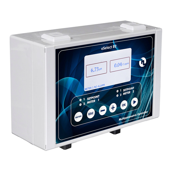
7.2. THE DISPLAY IN THE VARIOUS OPERATION MODES (PH – RX – CL) When the instrument is switched on, the display shows the measurement value and the type of measurement. 2013/05/15 04:52 WEDNESDAY T=25 7.47 pH 620mV eSelect B2 main screen SET1:ON mA1:12.4 SET1:OFF mA1:4.0 SET1:OFF mA2:12.4 SET1:OFF mA2:4.0... -
Page 19: Expert Menu Mode
MENU MODE: SIMPLE or EXPERT YEAR: put the current YEAR MONTH: put the current MONTH DAY: put the current DAY HOUR: put the current HOUR MINUTE: put the current MINUTE 7.3.2. EXPERT MENU MODE MENU SETUP MENU MODE EXPERT METER TYPE T SENSOR NONE SET TEMPERATURE... -
Page 20: Programming Menu Setup
7.4. PROGRAMMING MENU SETUP 7.4.1 MENU MODE MENU SETUP MENU MODE EXPERT METER TYPE T SENSOR NONE SET TEMPERATURE CALIBRATION MENU TIMEOUT 05:00 DELAY AT STARTUP 00:05 AUX OUTPUT MODE YEAR 2013 MONTH – – Chose the parameter by press key. -
Page 21: Menu Meter Type
7.4.2. MENU METER TYPE Starting from the MENU SETUP screen, enter in METER TYPE by pressing + key or – key. After selected METER TYPE press OK key to set the meter type between pH, Rx, Cl 20ppm,Cl 2ppm, Cl 200ppm, Cl 2000ppm. -
Page 22: Set Temperature
If PT100 will be set a PT100 sensor have to be connected to the dedicated connector. Selecting PT function, the temperature measured by PT100 probe is shown on the display (while the visualization of the measure is in progress). If NONE will be set it is possible to set the real temperature as show in next paragraph. 7.4.4. -
Page 23: Aux Output Mode
7.4.7. AUX OUTPUT MODE The controller has a calendar and an internal clock for the management of the exits with timer and the storage of the data recorded by the controller; in order to set up the clock the following settings must be carried out. Once the date and time are set, by pressing the + or - key, the choice are the follow: OFF function: the aux output is deactivated;... -
Page 24: Year, Month, Day, Hour, Minute
MENU SETUP MENU MODE EXPERT METER TYPE T SENSOR NONE SET TEMPERATURE 25.0 CALIBRATION MENU TIMEOUT 05:00 DELAY AT STARTUP 00:05 AUX OUTPUT MODE CLEANING CYCLE TIME 01:00 WEEKDAYS 1 MO TU WE.-- -- SA SU START TIME 1 02:00 –... -
Page 25: Menu Setpoint1, Setpoint2
7 .5. MENU SETPOINT1, SETPOINT2 Starting from the MAIN SCREEN in EXPERT MENU MODE press OK key than press + key to move the selector on MENU SETPOINT1 or MENU SETPOINT2. Press OK key to enter. Please note starting from SIMPLE MENU MODE into the SETPOINT1 and SETPOINT2 it is possible to set only the SETPOINT value and the working MODE ( acid or alkaline ). -
Page 26: Setpoint
MENU SETPOINT1 METER READING @20mA 14.00 7.5.1. SETPOINT After setting up the instrument, the SETPOINT values must be set: the instrument features two independent SETPOINTS ( SETPOINT1 and SETPOINT2 ) actuating two relating relay outputs. On the previous screen is show how set the values for these setpoints. After set the SETPOINT parameter, press OK key to move the cursor on right column and set the value by press + or –... -
Page 27: Ttl Mode
7.5.5. TTL MODE The instrument features two TTL (1-2) outputs that can operate in the proportional or ON/OFF mode. After set the TTL MODE parameter, press OK key to choose the operation mode of the TTL output selected: PROPORTIONAL or ON/OFF. In the proportional mode the frequency of pulses decreases approaching the SETPOINT until the minimum set value is reached, whilst in the ON/OFF mode the TTL output is actuated when the corresponding SETPOINT relay changes its position. -
Page 28: Menu Calibration
7 .6. MENU CALIBRATION Starting from the MAIN SCREEN press OK key than press + key to move the selector on MENU CALIBRATION. Press OK key to enter. MAIN SCREEN 2013/05/15 04:52 WEDNESDAY T=25 7.47 pH 620mV SET1:ON mA1:12.4 SET1:OFF mA1:10.4 Press OK key to enter SET1:OFF... -
Page 29: Calibrate Ph 7/Ref.point
7.6.1. CALIBRATE pH 7/REF.POINT The menu CALIBRATION allows the user to calibrate the instrument through the use of buffer solutions. After press CALIBRATE pH 7/REF. POINT dipping the probe in the pH 7 buffer solution is the calibration procedure’s first step. When the reading is stable, adjust the value by using the + and – keys and press key to ►... -
Page 30: Menu Alarm Settings
B2 and B3 controllers have one REMOTE input for each measure channel to which proximity sensor can be connected ( see page #4 for ESELECT B2 and page #6 for ESELECT B3 ). The proximity sensor when is inserted in the probe holder, signal the presence of water in the installation and therefore the need to start the inspection. -
Page 31: Pt100 Connection
8.2. PT100 CONNECTION As it is possible to see on the connection diagram represented in Fig. 1 the controller foresees the mounting of the PT100, 3 wire sensors. Regarding the two poles PT100 it is necessary to short circuit the two terminals of the clamps marked “C”... - Page 35 COD. DMU00193ML1-A (09-2013)
Need help?
Do you have a question about the eSelect B2 and is the answer not in the manual?
Questions and answers