2easy 2-wire Series Manual
Door station flush mount
Hide thumbs
Also See for 2-wire Series:
- Technical manual (30 pages) ,
- Installation and user manual (34 pages) ,
- Technical manual (26 pages)

Related Manuals for 2easy 2-wire Series


Summary of Contents for 2easy 2-wire Series
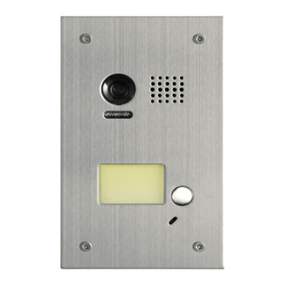
- Page 1 Door Station Model 603 / Flush Mount 2-wire series 2-Button 1-Button www.intelligenthomeonline.com...
-
Page 2: Parts And Functions
Introduction Door Station Model DT-603 is equipped with a high resolution colour CCD image sensor ARS 650TVL with wide angle of view 105 degrees. White LEDs enable the door station to work efficiently at night. The door station facia is made of medical stainless steel 2.5mm for better protection against cauterization. The call button is made of durable zink alloy. - Page 3 Terminals Descriptions Introduction Lock Control Jumper P L S + B U S Main Connect ion Port Lock Control Jumper : To program electric lock type Main Connect Port : To connect the bus line and electric lock BUS : Connect to the bus line, no-polarity PL : Additional power supply for the lock, connect to the power positive (power +) S+ : Lock power (+) output S - : Lock power (-) output...
- Page 4 Mounting Door Station Mounting Place name label if required. Connect the cable Cut out an appropriate size hole, and mount the wall box Place the front panel into the mounting box. Screw in with security screws Replacing Name Label Name label STEP 1 STEP 2 Unscrew the screws...
-
Page 5: System Wiring And Connections
System Wiring and Connections 1-Monitor Connection BUS(IM) BUS(DS) L1 L2 PL S+ S- Doorbell Button Switch Multiple Door Stations Connection If system has more than one door station installed, program their ID address before mounting them (see page 10 of manual) 4# Camera 3# Camera 2# Camera... - Page 6 Multiple Monitors Connection: Daisy Chain Up to 15 x video monitors (Aura, Alecto, Leda, Iris) can be connected in one system Code= 15 Code= 14 Code=0 100~240VAC BUS(IM) BUS(DS) Address:0...
- Page 7 Multiple Monitors Connection: Star with DBC4 Distributor Up to 15 x video monitors (Aura, Alecto, Leda, Iris) can be connected in one system Impedance Code=1 5 Code= 14 OFF ON switch Code= 13 Code= 12 Code=3 Code=2 Impedance OFF ON switch Code=1 Code=0...
-
Page 8: Electric Lock Connection
Electric Lock Connection Lock Controlled with Internal Power Lock can be powered from Door Station if: The lock is ‘Power-on-to-unlock’ 1 2 3 M agnetic lock, the jumper position in 1-2 The lock is 12V, and holding current is less 1 2 3 than 250mA Electric lock, the jumper position in 2-3... - Page 9 Unlock parameter settings via monitor (Aura, Alecto) INSTALLER SETUP About Local Address 00.00 Video Standard AUTO System Verson 00.01.00 Display Driver Front 1.Touch icon 2.Touch UNLOCK 3.A digital keypad will button and hold for 2s opens 1. Door station must be connected and powered up 2.
- Page 10 DIP switches settings for Multiple Monitor system (Models Cronus, Leda, Iris) There are 6 x DIP switches on the rear of video monitor and they are used to configure the ‘User Code’ for each monitor. Use Tables below for programming monitor ‘User Codes’ DIP switch 6 is ‘End of Line’...
- Page 11 6. Setup Monitors with User Code 0~15 will response calls from Button A Monitors with User Code 16~31 will response calls from Button B Door Station ID Address Up to 4 x Door Stations can be connected to one system. To find programming buttons A and B, remove steel facia of door station 1)Power-on and within 5 sec Press and hold both buttons "A"...
- Page 12 Unlocking Time Setting via Door Station The unlocking time can be set to 1~30 seconds. The default is 1s 1)Power-on and within 5 sec Press and hold "A" button for 3 2)Press and hold "B" button for 3 seconds seconds to enter programming mode background indicator Buzzer...
- Page 13 Ringtones Settings Door Station has two reasurring ringtones: (A)-single ringtone, (B)-continuous ringtone Can be switched off to silent (C) as well Deafult - single ringtone (A) 1)Power-on and within 5 sec Press and hold "B" button for 3 2)Press and hold "B" button for 3 sec to enter Programming mode background indicator Buzzer...
-
Page 14: Specifications
Specifications • Power Supply : DC 24V • Lock Power supply: 12Vdc, 300mA(Internal Power) • Power Consumtion: Standby 33mA; Working status 110mA; • Camera Image Sensor: Color ARS; 650 TV Lines • Unlocking time: 1~30s • Working temperature: -15ºC ~ 55ºC; •... -
Page 15: Cables Requirements
7.Cables Requirements This system transmits video and audio through the power cable. No Polarity connection Recommended cables Uncreened: twisted pair, flex multi-cores, speaker cable, CAT5/CAT6 Minimum requirements 0.5mm cable up to 2mm (depends on distance) monitor two or four monitors monitor monitor DBC4... - Page 16 -15-...
- Page 17 The design and specifications can be changed without notice to the user Right to interpret and copyright of this manual are preserved www.intelligenthomeonline.com...
Need help?
Do you have a question about the 2-wire Series and is the answer not in the manual?
Questions and answers