Table of Contents

Related Manuals for Roughneck 24923


Summary of Contents for Roughneck 24923
- Page 1 MECHANICAL FUEL METER OWNER’S MANUAL WARNING: Read carefully and understand all INSTRUCTIONS before operating. Failure to follow the safety rules and other basic safety precautions may result in serious personal injury. Item # 24923...
- Page 2 Thank you very much for choosing a Roughneck™ Product! For future reference, please complete the owner’s record below: Model: _______________ Purchase Date: _______________ Save the receipt, warranty and these instructions. It is important that you read the entire manual to become familiar with this product before you begin using it.
- Page 3 common sense and caution are factors that cannot be built into this product, but must be supplied by the operator. 1. Keep the work area clean and dry. Damp or wet work areas can result in injury. 2. Keep children away from work area. Do not allow children to handle this product. 3.
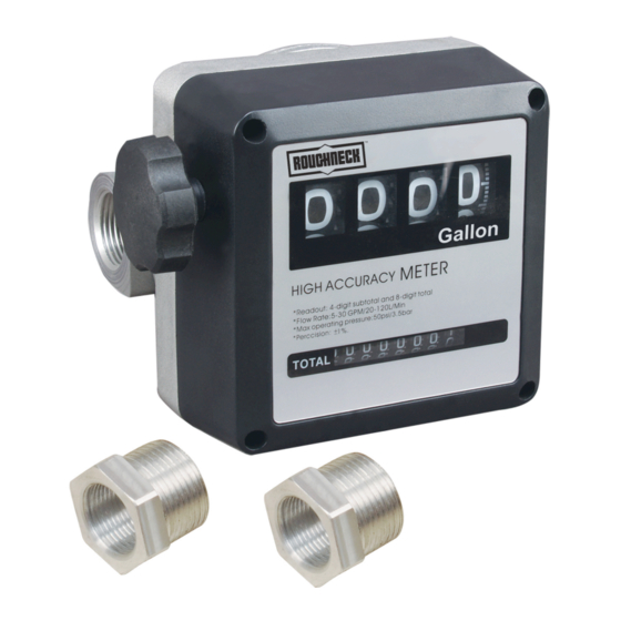
- Page 4 configurations (Figures B, C & D). The meter body is equipped with 4 blind holes which can be threaded for a possible fastening. If solid particles enter the measuring chamber the correct working of the nutating disk may be affected. Always filter the fluid by installing a filter (included) on the meter inlet.
- Page 5 GRAVITY-FED SYSTEMS The meter can also be used in gravity-fed fuel units where the flow is generated by the difference in fuel level between the tank and the nozzle outlet. As a general rule, a gravity-fed system, which is composed of a tank off the ground, a meter installed at the bottom of the tank, and a 9.8-ft.
- Page 6 it back towards the inlet in order to remove the O-ring (#17) from its seat at the outlet. 5. Remove the O-ring (#17) and divide the measuring chamber (#27) into two halves to check the inside of the chamber containing the nutating disk. To reassemble the chamber, reverse the above procedure.
- Page 7 DIAGRAM & PARTS LIST Description Quantity Description Quantity Name plate O-ring 110.72x3.53 Reset knob O-ring 23.47x2.62 External cover Measuring chamber Meter Measuring tray Screws 4x20 Measuring chamber Body cover Cylinder spring Screws 5x16 Screws 4x20 Bevel pinion O-ring 4.47x1.78 O-ring 3.62x2.62 By-pass adjusting screw Cover sealing O-ring 9.25x1.78...
Need help?
Do you have a question about the 24923 and is the answer not in the manual?
Questions and answers