Table of Contents
Advertisement
Quick Links
Advertisement
Table of Contents

Related Manuals for DataDirect Networks S2A9550


Summary of Contents for DataDirect Networks S2A9550
- Page 1 DataDirect Networks Silicon Storage Appliance S2A9550 User Guide Rev 4.0...
- Page 2 (including damages for loss of business profits, business interruption, loss of business information, and the like) arising out of the use or inability to use the software even if DataDirect Networks’ Licensor has been advised of the possibility of such damages.
- Page 3 Warranty: DataDirect Networks warrants that the DataDirect Networks Products accompanied by this limited Warranty are free from defects in material and workmanship for a period of two years from the date of original purchase from DataDirect Networks or an authorized DataDirect Networks reseller.
- Page 4 ., a Delaware corporation having a principal place of business at 500 Wind River Way, Alameda, CA 94501 (“Wind River”), IVER YSTEMS and DataDirect Networks, Inc., a California corporation having a principal place of business at the address set forth on the Production Exhibit attached hereto (“Customer”). ECITALS A.
- Page 5 TERMS OF THE EULA. This EULA is a legal agreement between you (either an individual or a single entity) and DataDirect Networks Corporation (“DATADIRECT”) for the DATADIRECT software and/or firmware accompanying this EULA, which includes the accompanying computer software and/or firmware, and may include associated media, printed materials and any “online”...
- Page 6 Complete Agreement. This EULA constitutes the entire agreement between the parties with respect to the use of the SOFTWARE AND/OR FIRMWARE, and supersedes all prior or contemporaneous understandings or agreements, written or oral, regarding such subject matter. DataDirect Networks S2A 9550 User Guide...
-
Page 7: Table Of Contents
Unpacking the S2A9550 ........ - Page 8 Restarting the S2A9550 ........
- Page 9 CLI/Telnet Session Control Settings ......3.9 Remote Management of S2A9550 ........77 3.9.1...
- Page 10 T a b l e o f C o n t e n t s 4.2.2 Warning Messages ......... 4.2.3 Timeout Messages .
-
Page 11: About This Guide
• Sections 3.1 to 3.8: These sections provide descriptions of the S2A9550’s comprehensive management capability. • Section 3.9: Remote Management of S2A9550. This section explains how to set up the Telnet and SNMP functions on the S2A9550 for remote monitoring and configuration. - Page 12 A b o u t t h i s G u i d e This page is intentionally blank. D ata Dir ec t N etworks S2A 955 0 U se r Gu id e...
- Page 13 ECTION Introducing the S2A9550...
- Page 14 This page intentionally left blank.
-
Page 15: Introduction
1.1.2 The S2A9550 The S2A9550 is designed specifically to support high bandwidth, shared access to and backup of large banks of data, and rich content. It enables a multi-vendor environment comprised of standalone and clustered servers, workstations and PCs to access and back up data stored in centralized or distributed storage devices in an easy, cost effective and reliable manner. - Page 16 • Hot-Swappable and Redundant Components The S2A9550 utilizes redundant, hot-swappable power supplies and cooling modules that can be replaced while the system is running. D at a Dir ec t N et w orks S 2A 955 0 Us er Gu id e...
-
Page 17: The S2A9550 System Hardware
The basic S2A9550 (Figure 1-1) includes: • A single unit (with a minimum of 2.56 GB cache memory) • Ten SFP (Small Form-factor Pluggable) cables which connect the S2A9550 to the FC drive enclosures (Refer to Cabling & Switching Information for S2A8500 &... -
Page 18: Power Supply And Fan Modules
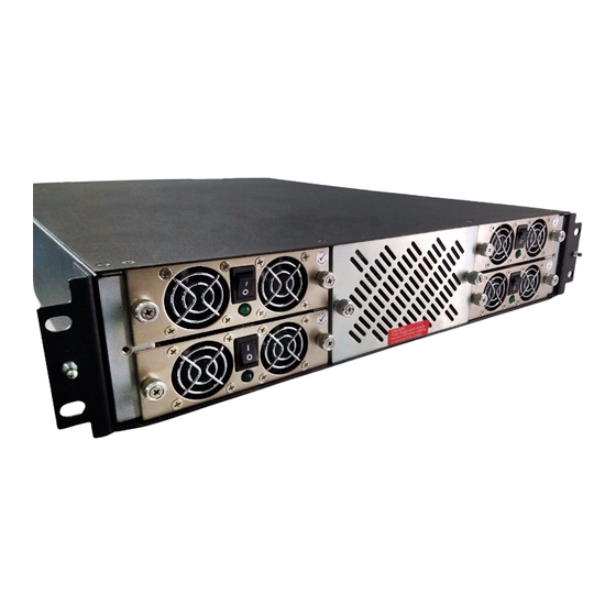
Introduction 1.2.1 Power Supply and Fan Modules Each S2A9550 is equipped with four (4) Power Supply/Cooling modules and one (1) fan module . The PSU (power supply unit) voltage operating ranges are nominally (Figure 1-3) 110V or 230V AC, selected automatically. -
Page 19: I/O Connectors And Status Led Indicators
Introduction 1.2.2 I/O Connectors and Status LED Indicators Figure 1-4 shows the position of the I/O connectors at the back of the S2A9550 4FC unit. Disk Ports Host 1 Host 3 Unit 1/Unit 2 Host 2 S2A Link Host 4... -
Page 20: Host And Disk Connectivity
1.2.3 Host and Disk Connectivity The S2A9550 includes four (4) 4 Gb/s full duplex Fibre Channel host ports. The host ports are hard-wired for non-OFC optical connections utilizing SFP (Small Form-factor Pluggable) connectors. The disk ports utilize ten standard copper SFP connectors. - Page 21 ECTION Installing the S2A9550...
- Page 22 This page intentionally left blank.
-
Page 23: Installation Overview
This list provides an overview of the installation process. The following sections explain these steps in greater detail. Unpack the S2A9550 system. Install the S2A9550 and drive enclosures in the 19" cabinet(s) as directed in the Rackmounting Manuals. (See Appendix A for physical dimensions and weight of the S2A9550 Set up and connect the drive enclosures to the S2A9550. - Page 24 Installation This page is intentionally blank. Da ta Dir ec t Ne twor ks S 2A 9 55 0 U se r G ui de...
-
Page 25: Setting Up The S2A9550
Retain all cartons and packing materials in case you need to store or ship the system in the future. Visually inspect the S2A9550 chassis and all components for signs of external damage. If you detect any problems, please call DataDirect Networks Customer Service. -
Page 26: Connecting The S2A9550S In Dual Mode
2.2.4 Connecting the S2A9550 If you are using the SF family of enclosures with the S2A9550, please refer to Section C.2 for information on how to set up the enclosures and connect them to the S2A9550. You may also refer to to Cabling & Switching Information for S2a 8500 & S2A9550 and Drive Enclosures 96-00164-001. -
Page 27: Laying Out Your Storage Drives
Please refer to Appendix C for further information on setting the SF enclosure ID. 2.2.6 Laying Out your Storage Drives The S2A9550 is capable of managing up to 125 tiers. Tiers are the basic building blocks of the SS2A9550. One tier contains 10 drives—eight data drives (Channels A through H), one parity optional drive (Channel P), and one spare drive (Channel S). -
Page 28: Connecting The Rs-232 Terminal
Hyperterminal). Then you may set up the remote management functions and configure/monitor the S2A9550 remotely via Telnet. Connect your terminal to the CLI port at the back of the S2A9550 using a standard DB-9 femail-to-male Null Modem cable (Figure 2-3) -
Page 29: Basic Key Operations
Installation Then bring up your terminal window and use the following settings for your serial port: Bits per second: 115,200 Data bits: 8 Parity: None Stop bits: 1 Flow control: None 2.2.7.1 Basic Key Operations The command line editing and history features support ANSI and VT-100 terminal modes. The command history buffer can hold up to 64 commands. -
Page 30: Powering On The S2A9550
Check that all your drive enclosures are powered up and the drives are spun up and ready. Turn on the power supplies on the S2A9550 unit(s). The S2A9550 goes through a series of system diagnostics and the bootup sequence is displayed on your terminal. Wait until the sequence is complete and the S2A9550 system prompt is displayed. -
Page 31: Configuring The S2A9550
HELP feature. 2.3.1 Setup Planning The S2A9550 offers great flexibility in defining LUN configurations and optimizing performance for specific applications. Before proceeding with your S2A9550 configuration, it is necessary to determine the requirements for your SAN environment, including the types of I/O access (random or sequential), the number of storage arrays (LUNs) and their sizes, and user access rights. -
Page 32: Configuration Options
S2A9550 information on how to set up the for remote management and configuration. S2A9550 Connect your terminal to the CLI port at the back of the S2A9550 using a standard DB-9 female-to-male Null Modem cable (Figure 2-5) RS-232 Interface Figure 2-5 CLI Port on the S2A9550... -
Page 33: Login As Administrator
This tells the S2A9550 how the tiers are laid out with respect to the drives’ AL_PA. Hence, the system can correctly light the drive’s LED and provide visual indication of a specific drive, tier, and LUN. -
Page 34: Verifying Connections For Sf6016 Enclosures
NOTE : If you have other types of drive enclosures, select Tier Mapping Mode 0. The S2A9550 might be able to monitor the status of your enclosures; however, DataDirect Networks is unable to guarantee compatibility with unqualified third party devices. - Page 35 Figure 2-7 Current Tier Configuration Screen Each letter under the “Disk Status” column represents a healthy drive at that channel as shown in the figure above. Verify that all your drives can be seen by the S2A9550. “Unhealthy” drives appear as follows: •...
-
Page 36: Cache Coherency And Labeling In Dual Mode
Cache coherency: Not established. Cache coherency timeout: 2 Figure 2-9 Dual S2A9550 Configuration Screen If you require multi-pathing to the LUNs, enable cache coherency. If you do not require multi-pathing, disable cache coherency. To enable/disable the cache coherency function, use the command: DUAL COHERENCY=ON|OFF <Enter>... -
Page 37: Configuring The Storage Arrays
2.3.10 Configuring the Storage Arrays NOTE : In dual mode, LUNs are “owned” by the S2A9550 unit via which they are created. Hosts only see the LUNs on the S2A that they are connected to, unless cache coherency is enabled. - Page 38 - Then select the tier(s) by entering the Tier number. Enter each one on a new line and press the key. The tiers are numbered from 1 through 125. <Enter> <Enter> <Enter> - Enter the block size in Bytes: 512 <Enter> DataDirect Networks S2A 9550 User Guide...
-
Page 39: Setting Security Levels
2.3.11.1 User Authentication (Recommended for SAN Environment) Each user connected to the S2A9550 is identified by its World Wide Name (WWN) and is given a unique user ID number. The S2A9550 can store configuration for up to 512 users and the security settings apply to all host ports. - Page 40 If LUN Zoning chart is NOT empty, follow the procedure in Section 2.3.11.2 to remove all mapping to internal LUNs. To add a user: Type: user audit=on The S2A9550 reports which users are connected. <Enter> Type: user add <Enter> Enter the ID number of the user to be added (which is 0 in this example, see Figure 2-15).
-
Page 41: Host Port Zoning (Anonymous Access)
Figure 2-15 Configuring the User Access to LUNs 2.3.11.2 Host Port Zoning (Anonymous Access) This type of set up should only be used for non-SAN environment. Users are given the “general admission” to the data. DataDirect Networks S2A 9550 User Guide... - Page 42 The S2A9550 installation is complete at this point. Your client systems should now be able to access the LUNs on the S2A9550. If you want to remotely monitor the S2A9550, please refer to Section 3.9 for information on how to configure the network interface settings.
- Page 43 ECTION Using the S2A9550 Management & Administrative Facilities...
- Page 44 This page intentionally left blank.
-
Page 45: Managing The S2A9550
Any RS-232 terminal or terminal emulator (such as Windows Hyperterminal) can be used to configure and monitor the S2A9550. Connect your terminal to the CLI port at the back of the S2A9550 using a standard DB-9 female-to- male Null Modem cable... -
Page 46: Administrator And User Logins
At the general purpose user access level, you are only allowed to view the status and configuration information of the system. If the S2A9550 determines that the individual does not have the proper privileges, it will return a message: <user entered command>: Permission denied 3.1.3.1... -
Page 47: Configuration Management
Current security level: Administrative. Figure 3-5 “Who Am I Screen Configuration Management The S2A9550 provides uniform configuration management across heterogeneous SAN. Status of host ports and storage assets are continuously being monitored. 3.2.1 Configure and Monitor Status of Host Ports The status information of the host ports can be obtained at any time. -
Page 48: Host Status
Disk and Channel Information The DISK command displays the current disk configuration and the status of the ten disk channels on the S2A9550 (Figure 3-9) D at aD ir ec t N et w o rk s S 2A 9 55 0 Us er Gu ide... - Page 49 M a n a g i n g t h e S 2 A 9 5 5 0 S2A [1]: disk Disk Channel Status Disk Channel A healthy. Disk Channel B healthy. Disk Channel C healthy. Disk Channel D acquiring loop synchronization. Disk Channel E healthy.
-
Page 50: Tier View
3.2.2.2 Tier View Tiers are the basic building blocks of the S2A9550. One tier contains ten drives: eight data drives (Channels A through H), one parity drive (Channel P), and an optional spare drive (Channel S). Drives that have the same AL_PA across all ten channels are put on the same tier. The tier that contains the drives with the highest AL_PA value is recognized as Tier #1. - Page 51 M a n a g i n g t h e S 2 A 9 5 5 0 S2A [1]: tier Tier Status Capacity Space Available Tier Owner (Mbytes) (Mbytes) Disk Status Lun List ----------------------------------------------------------------- 280012 271820 ABrDEFGHPS 280012 271820 ABCDEFGHPS 280012 271820...
-
Page 52: Lun View
M a n a g i n g t h e S 2 A 9 5 5 0 'F' indicates the failed disk (if any) on the tier. 'R' indicates the replaced disk (if any) on the tier. 'Sp H' indicates if the spare disk that is physically on the tier is healthy. 'Sp A' indicates if the spare disk that is physically on the tier is available for use as a replacement. -
Page 53: Adding/Removing Storage Assets
Figure 3-16 LUN Reservations Screen 3.2.2.4 Adding/Removing Storage Assets The S2A9550 supports up to 125 tiers (depending on individual disk enclosure’s AL_PA numbering scheme). As your storage demand grows, new tiers can easily be added without affecting system operations. Use the DISK SCAN command to check each disk channel in the system for any new disks. New tiers are automatically added to the system when the disks are detected. -
Page 54: Display Information Of Ses Devices
The tier mapping information also allows the S2A9550 to properly light the enclosure fault LEDs. -
Page 55: System Network Configuration
The S2A9550 currently supports the SF and SA families of drive enclosures. If you have other types of drive enclosures, the S2A9550 might still be able to monitor the status of your enclosures. Component failures such as power supply, fan, and drive will be reported. However, visual indication of the drives, tiers, and LUNs will not be supported. -
Page 56: Telnet
IP address but each S2A9550 can specify a different destination port. To change the destination port number for syslog packets for the current S2A9550, use command: NETWORK SYSLOGPORT=<port number>. Both S2A9550s in the couplet pair will share the same syslog destination IP address but each S2A9550 can specify a different destination port. -
Page 57: Api Server Connections
To affect the API Server connection availability only temporarily during the current power- cycle, refer to the API command (see Section 3.8.2). To specify the API Server port number for the current S2A9550, use the command: NETWORK API_PORT=<port number>. The system must be restarted before the changes will take effect. Valid ports are 0 to 32768. -
Page 58: Restarting The S2A9550
All hosts and users actively using the S2A9550 should be safely shutdown before using this command. The S2A9550 will halt all I/O requests and save the data to the disks. It will then ask if the disks should be spundown. Disks should be spundown before they are moved. The unit can be safely turned off after using this command. -
Page 59: Setting The System's Date And Time
<Enter>. example, to change the time to 2:13:10pm, type: TIME 14:13:10 <Enter>. 3.2.7 Saving the S2A9550’s Configuration The SAVE command can be used to save the system configuration to non-volatile memory (Figure 3- S2A [1]: save Saving system parameters.. Done. -
Page 60: Lun Management
(Figure 3-23) NOTE : In dual mode, LUNs will be “owned” by the S2A9550 unit via which they are created. Hosts will only see the LUNs on the S2A9550 that they are connected to, unless cache coherency is used. S2A [1]: lun... -
Page 61: Formatting A Lun
M a n a g i n g t h e S 2 A 9 5 5 0 To add a 64 bit LUN, type: LUN ADD64=x <Enter> where “x” is the Logical Unit Number <0..127>. For either case, the system prompts you for all the necessary information to create the LUN and indicates if the LUN was successfully added to the system. -
Page 62: Moving A Lun (Dual Mode Only)
If you need to delete a LUN from the system, type: LUN DEL=x where “x” is the LUN <0..127>. <Enter>, This will erase all the data on the LUN. You can only delete a LUN which is owned by the S2A9550 that you are logged into. 3.2.9.8 SCSI Reservations The LUN RELEASE=x|x.y command allows you to release all SCSI reservations on a LUN. -
Page 63: Manual Drive Rebuild
• TIER STOP - to abort all the current rebuild operations. 3.2.11 Couplet Configuration (Cache/Non-Cache Coherent) S2A9550 There are two primary couplet S2A9550 configurations: cache coherent and non-cache coherent. The DUAL command displays information about couplet system configuration (Figure 3-27) S2A [1]: dual Dual S2A Configuration... -
Page 64: Non-Cache Coherent
LUNs 0, 1, and 2 respectively. S2A9550 1 owns LUNs 0 and 1 while S2A9550 2 owns LUN 2. The user is physically connected to S2A9550 1, thus, it will only see LUNs 0 and 1. The user will not be able to access LUN 2. -
Page 65: Labeling The S2A9550 Unit(S)
You may change the label assigned to each S2A9550 unit. This allows you to uniquely identify each unit in the S2A9550 system. The CLI prompt for each S2A9550 is built by adding a colon and a space at the end of the label. Each S2A9550 can have a label up to 31 characters long. -
Page 66: Performance Management
M a n a g i n g t h e S 2 A 9 5 5 0 Performance Management The S2A9550 offers great flexibility in optimizing performance with extensive monitoring and reporting capability. 3.3.1 Optimization of I/O Request Patterns The S2A9550 manages the pre-fetch and cache efficiency by LUN. -
Page 67: Prefetch Settings
M a n a g i n g t h e S 2 A 9 5 5 0 3.3.1.4 Prefetch Settings When the system receives a request, it can read more data than it has been requested. Prefetch tells the system how much data to look ahead. This will improve performance if your system needs to perform sequential reads. -
Page 68: Audio/Visual Settings Of The System
Default setting is OFF. NOTE : Note: When AV mode is enabled, the S2A9550 will not retry check conditions on disks. Since this increases the risk of disk failures, this should be used in AV environments only. -
Page 69: Locking Lun In Cache
Once a LUN is locked, the data that is gathered to service read and write commands will stay permanently in the cache. The S2A9550 will continue to fill up the cache until 50% of the total cache is filled with data from locked LUNs, while the other 50% of the cache is reserved to service I/O for unlocked LUNs. -
Page 70: Locking / Unlocking A Lun
LUN. Once the size of the locked LUNs exceeds 50 % of the total cache, the S2A9550 will have to create cache space to process a new I/O, by removing older data from the locked portion of cache. The Least Recently Used (LRU) algorithm is used to determine which locked data to remove from cache. -
Page 71: System Performance Statistics
M a n a g i n g t h e S 2 A 9 5 5 0 3.3.4 System Performance Statistics The S2A9550 monitors pre-fetch and cache efficiency, request distribution, transaction, and transfer rates by port. The STATS command will display the performance statistics for the host ports, disk channels, and cache memory . - Page 72 M a n a g i n g t h e S 2 A 9 5 5 0 S2A [1]: stats delay Command Delay Statistics Time Host Host Disk Disk seconds Reads Writes Reads Writes 1690087 1446110 281633 253704 82900 79522 87112 45260...
- Page 73 M a n a g i n g t h e S 2 A 9 5 5 0 The STATS TIERDELAY=<tier> command will display a histogram of the time it takes for the disk I/O request to complete for all the disks in the specified .
- Page 74 M a n a g i n g t h e S 2 A 9 5 5 0 The STATS DUAL command displays the statistics for the dual mode messages (Figure 3-38) S2A [1]: stats dual Dual Message Statistics Message Total Msgs/s Lock requests...
-
Page 75: Resources Allocation
M a n a g i n g t h e S 2 A 9 5 5 0 3.3.5 Resources Allocation 3.3.5.1 Background Format/Rebuild Operations Format and rebuild operations are background processes and their rates can be adjusted to minimize their impact on system performance. -
Page 76: Ses Device Monitoring Rate
M a n a g i n g t h e S 2 A 9 5 5 0 NOTE : It is recommended that you run LUN VERIFY in continuous mode, if at all possible, since it can help increase disk reliability. The LUN DELAY=x command sets the system verify delay value to 'x'. -
Page 77: Security Administration
The read-only and read/write privileges can also be specified for each LUN and for each user. The “place holder LUN feature allows the S2A9550 administrator to map a zero capacity LUN to a host or group of hosts (via zoning or user authentication). The administrator can then create a real LUN and map it to the host(s) to replace the “place holder”... -
Page 78: Zoning (Anonymous Access)
This type of configuration provides the first-level protection. LUN identification scheme can be customized for each host port. Any unauthorized user accessing the S2A9550 will be considered “anonymous” and granted the “zoning” rights for the host port to which they are connected. -
Page 79: User Authentication
64-bit World Wide Name and is given a unique user ID number. The Ports column indicates which host ports, on each S2A9550, the user is allowed to log into. The LUN Zoning chart indicates which internal LUNs the user will have access to (with read-only and read/write privileges) and where the internal LUN will appear to the user. -
Page 80: Firmware Update Management
NOTE : Before you begin upgrading the firmware, make sure all access to S2A9550 are stopped, all volumes on the storage array are unmounted and allow sufficient time for the S2A9550 to flush all cached data. Collect and save the output of the following commands before you update the firmware:... - Page 81 Issue the RESTART command on the S2A9550 unit(s) to restart. 10. For dual mode only: After both S2A9550 are back on-line, use the DUAL command to verify that both S2A9550 units are healthy. If either S2A9550 shows failed, login to the healthy S2A9550 and issue the DUAL HEAL command.
-
Page 82: Remote Login Management
Telnet session. Use the TELNET command to display the current setting. NOTE : The Telnet capability is reset to ON after S2A9550 restart. To turn off Telnet access permanently, use the NETWORK command. The TELNET STATS command allows the administrator to view various statistics maintained on remote Telnet sessions . - Page 83 M a n a g i n g t h e S 2 A 9 5 5 0 [Remote TELNET session ON] Local SUBshell S2A [1]: telnet Time: 19:49:48 Date: 03/29/2002 Remote Telnet Session Information: --------------------------------- Owner's Name : admin Security Level : Administrative Remote Site IP Address : 010:123:139:005...
-
Page 84: The System Logs
The System Logs 3.7.1 Message Log All S2A9550 events are logged and saved in non-volatile memory. The log will automatically roll over when it is full. To display the log of previous system messages, enter command LOG. To clear the log of all previous messages, enter command LOG CLEAR. -
Page 85: Displaying System's Uptime
M a n a g i n g t h e S 2 A 9 5 5 0 To display the number of LUN array parity errors detected by the system, use the faults arrayparity command. The system saves the counts for each tier of all the LUNs. To clear the count of LUN array parity errors in the system, use the faults arrayparityclear command. -
Page 86: Other Utilities
M a n a g i n g t h e S 2 A 9 5 5 0 Other Utilities 3.8.1 APC UPS SNMP Trap Monitor The APC_UPS command will display the status of the APC UPS SNMP trap monitor (Figure 3-59) S2A [1]: apc_ups APC UPS SNMP trap monitor is off. -
Page 87: Internal Mirrored Groups (Img)
The MIRROR STOP command can be used to abort the merge procedure all together. 3.8.4 Changing Baud Rate for CLI Interface To display the current serial console setting of the S2A9550 unit, enter command: CONSOLE (Figure 3-63) S2A [1]: console Serial console baud rate is 115200 baud. -
Page 88: Cli/Telnet Session Control Settings
M a n a g i n g t h e S 2 A 9 5 5 0 The CONSOLE BAUD command can be used to change the baud rate of the CONFIG port of the S2A9550 (Figure 3-64) S2A [1]: console baud... -
Page 89: Remote Management Of S2A9550
This section provides information on how to set up the S2A95500 for remote management and configuration. The S2A9550 can be managed locally through the RS-232 interface, or remotely via Telnet. The Administrative Utility is the same regardless of the management interface (RS-232 or Telnet). - Page 90 The default destination port number for Syslog packets is 514. If you need to change it, use the command: NETWORK SYSLOGPORT=<port number>. 10. Set up the routing table which describes how the S2A9550 can communicate with the hosts on other networks. Use the ROUTE command to display the current settings...
-
Page 91: Login Names And Passwords
R e m o t e M a n a g e m e n t o f S 2 A 9 5 5 0 11. If you have couplet S2A9550, connect (or Telnet if this is not the initial set up) and log into the other S2A9550. -
Page 92: S2A9550 Implementation Of Snmp
- Any changes in S2A9550 MIB. If any variable in the S2A9550 MIB changes, a trap will be sent. For example, when a power supply fails or is replaced, a trap will be sent. Trap includes ASCII string declaring new status of S2A9550 element. - Page 93 ECTION Supporting the S2A9550...
- Page 94 This page intentionally left blank.
-
Page 95: Maintaining The S2A9550
Trouble Shooting Maintaining the S2A9550 This section provides information regarding error recovery on the S2A9550. To display the list of all current system and drive enclosure faults, enter command: FAULTS 4.1.1 Component Failure Recovery The S2A contains redundant and hot-swappable fans and power supplies. A single component failure, therefore, will not shut down the system. -
Page 96: Fan Failure
If more than one disk is failed in a single tier, only the first disk to fail will be replaced by a spare disk. Any disks which fail after the first in each tier will not be reconstructed using a hot spare. DataDirect Networks S2A 9550 User Guide... -
Page 97: Single Drive Failures
(if available) is replacing the failed drive. If your drive enclosure is on DataDirect Networks’ official S2A compatibility list, the Fault LED on the failed drive will turn amber. The error is also written to the event log. The S2A will rebuild the drive automatically once it finds a suitable spare drive. -
Page 98: Multiple Drive Failures And Channel Failures
Any single channel failure can be recovered. Before you replace any drives: Use the TIER command to check the current disk status and see if the drives (Figure 4-73) failed are all on the same channel. DataDirect Networks S2A 9550 User Guide... -
Page 99: Component Failure On Enclosures
If your enclosures provides SES communications, status information of the enclosures, including power supply, fan, and presence of drive, will be obtained and evaluated. If a change in status is found, an “SES” message is displayed on your console (Figure 4-75) DataDirect Networks S2A 9550 User Guide... -
Page 100: Error Correction (Bad Block Management)
While the rebuild progresses, the Bus Parity Error Correction process runs in the background awaiting bus parity error should any occur duing the rebuild. If activated, the Bus Pairty Error Correction will attempt to rebuild the sector again. DataDirect Networks S2A 9550 User Guide... -
Page 101: S2A9550 Messages And Descriptions
Timeout: Read Disk 1A, Id:1 These messages indicate that the S2A9550 has timed out waiting for a data transfer such as a read from an initiator. This means that the unit may have trouble communicating with an initiator or a disk... -
Page 102: Informational Messages
Timeout: Cache diagnostic disk channel A. The S2A9550 performed a diagnostic test on the SDRAM from the host and disk sides but the test took too long to complete. This error will prevent the system from running normally. This may indicate a problem with the hardware. -
Page 103: Disk Boot-Up Error Messages
Waiting for disks to Boot: 3FF The S2A9550 sent a request to the disk channels to perform a LIP and to report the results back. This message indicates that the LIP request is taking a long time and the S2A9550 is still waiting. The LIP results will be delayed if a disk is in the process of spinning up. - Page 104 Check the disk to make sure it is correct. Could not find Disk 1A The above message indicates that the S2A9550 could not locate a disk that is part of a valid LUN in the system. The data in the LUN will not be available until the S A 9550 can locate the disk or the disk is marked as failed.
- Page 105 It may be in the wrong location or it may have been replaced without informing the S2A9550. The data in the LUN’s will not be available until the original disk is restored or the disk is marked as failed. Make sure the disk is installed correctly.
-
Page 106: Disk Error Messages
No Spares available. The above message indicates that the S2A9550 failed a disk in the array but could not find a spare disk to replace it with. This message is informational only. The tier containing the failed disk will begin operating in degraded mode. - Page 107 The timeout messages may be generated under heavy I/O conditions when an error occurs, such as a disk failure, or a LIP on the Fibre Channel bus. This could also indicate that the S2A9550 might have trouble communicating with the disk. Timeouts should generally not occur during normal operation and should be reported if they keep reappearing.
- Page 108 S 2 A 9 5 5 0 M e s s a g e s a n d D e s c r i p t i o n s Disk Login failed 1A The above message indicates that the S2A9550 found a device on the Fibre Channel bus but could not login with it. Make sure the disk is installed correctly and cycle power on the disk.
- Page 109 SCSI Error Status: %x Disk 1A ID EF The above message indicates that the S2A9550 received a SCSI error status on a command it sent to a disk. The S2A9550 will display any valid sense data returned with the status. Check the disk and replace it if it is no longer functional.
-
Page 110: Host Error Messages
The above message indicates that a SCSI command from an initiator was aborted. The abort may have come from the initiator, a target reset, or from a timeout in the S2A9550. This could also indicate that the S2A9550 might have trouble communicating with the initiator. Aborts should generally not occur often during normal operation and should be reported if they keep reappearing. -
Page 111: Rebuild Error Messages
Read Under Run LUN:1 length:%x DL:%x The above messages indicate that an initiator sent a SCSI read or write command to the S2A9550 with a length in the CDB which is less than the length in the DL field of the command frame. This means that the initiator is not building the command frames correctly. -
Page 112: Ses (Scsi Enclosure Services) Messages
Rebuild aborted on LUN: 0 Format aborted on LUN: 0 The above messages indicate that the S2A9550 aborted a rebuild or format operation on a LUN. This usually occurs when the user cancels a format or rebuild operation. These messages are intended to be informational only. - Page 113 ECTION Appendices...
- Page 114 This page intentionally left blank.
- Page 115 S 2 A 9 5 5 0 T e c h n i c a l S p e c i f i c a t i o n s Technical Specifications The technical specifications of the S2A9550 are given below. Configuration, Performance & Capacity...
- Page 116 S 2 A 9 5 5 0 T e c h n i c a l S p e c i f i c a t i o n s Physical, Power & Environmental 3.5" × 19.0" × 25", 40 lbs S2A chassis (H×W×D, Weight) Electrical/AC...
- Page 117 S 2 A 9 5 5 0 T e c h n i c a l S p e c i f i c a t i o n s Safety Guidelines for Rack Installation Please follow the following safety guidelines when installing the S2A9550 in a rack: Elevated Operating Ambient Temperature If installed in a closed or multi-unit rack assembly, the operating ambient temperature of the rack environment may be greater than room ambient.
- Page 118 S 2 A 9 5 5 0 T e c h n i c a l S p e c i f i c a t i o n s This page intentionally left blank. D at aD ire ct N et w o rk s S2 A 95 50 Us er Gu ide...
Need help?
Do you have a question about the S2A9550 and is the answer not in the manual?
Questions and answers