
Related Manuals for Mitsubishi Electric PLK-J4040RH


Summary of Contents for Mitsubishi Electric PLK-J4040RH
- Page 1 INDUSTRIAL SEWING MACHINE MODEL PLK-J4040RH TECHNICAL MANUAL SEWING MACHINE HEAD A180E823P02...
- Page 2 FOR SAFE USE Before the installation, operation, and inspection for this product, read the “FOR SAFE USE” and the technical manuals carefully. Also read the other technical manuals, “Control Unit” and “Operation Panel” describing some instructions, which are not in this manual, and use the sewing machine properly. SAFETY INDICATIONS Indicates that incorrect handling may cause hazardous conditions, resulting DANGER...
- Page 3 SAFETY PRECAUTIONS DANGER To prevent from receiving an electric shock, always turn off a power switch and unplug power supply when opening a control box, and then open after ten minutes passes. CAUTION USAGE ENVIRONMENT Please do not operate the sewing machine under the following conditions. (1) In the ambient temperature of 35 degrees (95°F) or more than 35 degrees, or the ambient temperature of 5 degrees or less than 5 degrees (41°F).
- Page 4 SEWING (1) Please make sure to turn the power switch off before installing or replacing needles. (2) Please pay attention for the fingers not to be injured by the needle point. (3) Please make sure to turn power switch off before lubricating. (4) Please pay attention that oil does not get on your skin or in your eyes as it may cause an inflammation.
-
Page 5: Table Of Contents
CONTENTS 1. STRUCTURE OF THE SEWING MACHINE···································· 2. SPECIFICATIONS····································································· 3. INSTALLATION········································································ 3-1. Installation of the foot switch··································································· 3-2. Connection of the air tube······································································· 3-3. Installation of the thread stand································································· 3-4. Installation of the eye guard···································································· 3-5. Installation of the rubber cushion······························································ 4. - Page 6 6-6. Adjustment of the thread take up spring···················································· 6-6-1. Adjusting movable range of the thread take up spring····························· 6-6-2. Adjusting intensity of the thread take up spring····································· 6-7 Adjustment of the air pressure································································· 7. VARIOS ADJUSTMENT····························································· 7-1. How to exchanging the tension spring of the needle thread tensioner unit········ 7-2.
-
Page 7: Structure Of The Sewing Machine
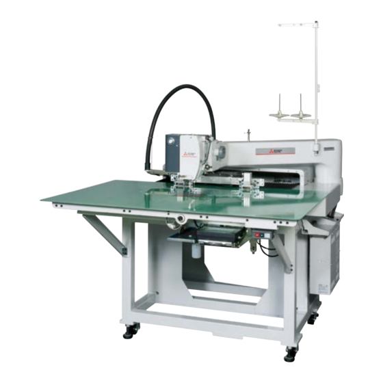
1. STRUCTURE OF THE SEWING MACHINE PLK-J4040RH electronic pattern sewing machine consists of the following main parts. <7> <1> <2> <8> <4> <3> <6> <5> <1>: Sewing machine head <2>: Halt switch <3>: Control box <4>: Operation panel <5>: Work holder switch <6>: Start switch <7>: Thread stand <8>: Sewing machine table - 1 - From the library of Superior Sewing Machine &... -
Page 8: Specifications
Storable sewing data item 9,000 patterns Data memory USB memory Type of motor (Needle side) Mitsubishi Electric 750W direct servo motor Type of motor (Hook side) Mitsubishi Electric 400W direct servo motor Work holder Jig eject system Needle bar stroke 50.8 mm... -
Page 9: Installation
3. INSTALLATION CAUTION (1) Please have some specialists, who have enough experience for the sewing machine installations, install the sewing machine. (2) Please have a Qualified Electrician perform necessary electric wiring. (3) Please do not operate until the sewing machine is repaired when any damage or fault is found on the sewing machine at the installation. -
Page 10: Connection Of The Air Tube
3-2. Connection of the air tube Insert the one end of the air tube (8mm Diameter) into the intake air fitting (No.3) of the filter regulator (No.2) then, join the other end of the air tube with the suitable air coupling to be adopted with the air supply source provided in your factory. -
Page 11: Installation Of The Eye Guard
3-4. Installation of the eye guard (1) Mount the eye guard (No.1) with screw (No.2) to sewing machine head. <1>: Eye guard unit <2>: Screw <2> <1> 3-5. Installation of the rubber cushion in the direction of “a” arrow and locate the rubber cushion (1) Screw the adjust foot (No.2) (No.1) -
Page 12: Lubrication
4. LUBRICATION CAUTION (1) Please make sure to turn power switch off before lubricating. (2) Please pay attention that oil does not get on your skin or in your eyes as it may cause an inflammation. (3) Please make sure to keep oil out of the reach of children who may drink oil by mistake. NOTICE Please make sure to lubricate when operating for the first time after the installation. -
Page 13: Proper Operation
5. PROPER OPERATION 5-1. Installation of the needle CAUTION (1) Please make sure to turn the power switch off before installing or replacing needles. (2) Please pay attention for the fingers not to be injured by the needle point. (1) Attach the needle holder (No.2) to the needle bar (No.1) then, insert a new needle (No.3) until the needle head is reached the end of the guide groove of the needle bar (No.1). -
Page 14: Threading The Needle Thread
5-2. Threading the needle thread CAUTION (1) Please turn the power switch off when threading a needle. (1) Thread the needle thread as shown on the figure. - 8 - From the library of Superior Sewing Machine & Supply LLC - www.supsew.com... -
Page 15: Winding The Bobbin Thread
5-3. Winding the bobbin thread CAUTION (1) Please do not touch the rotating part during winding thread. Doing so may cause injury and/or the machine failure. (1) Fit the bobbin (No.1) to the bobbin winder (No.2). In this time, insert the pin (No.5) which has bobbin winder (No.2) to the hole of the bobbin (No.1). -
Page 16: How To Opening The Bobbin Access Door
5-4.How to opening the bobbin access door When exchanging the bobbin, please open the bobbin access door (No.1) referring the following paragraph. The bobbin access door has center of the machine table. (1) Turn the opening switch (No.2) in the direction of the arrow which has front lower side of the table. The bobbin access door opens when opening switch (No.2) becomes state in <B>... -
Page 17: Setting The Bobbin
5-5. Setting the bobbin (1) Insert the bobbin (No.2) to the inner hook (No.1). (2) Close the inner hook latch (No.3) and set the bobbin (No.2). (3) Pull the bobbin thread (No.4) into the slit (No.5) and pass through the thread hole (No.6). (4) Pull the bobbin thread (No.4) then, check with the bobbin (No.2) if it is rotated to the arrow direction. -
Page 18: How To Operating The Jig Eject System
5-7.How to operating the jig eject system (1) Prepare the type of the work holder for jig eject system, and install the cassette jig right (No.1) and cassette jig left (No.2) which are enclosed in accessory box. NOTE For more information concerning about dimension, please refer to the last chapter <10-1.>. (2) Install the cassette jig right (No.1) and cassette jig left (No.2) to the inmost part of the each jig eject system (No.3). -
Page 19: Operation Of The Halt Switch
5-8. Operation of the halt switch (1) If accidents such as a thread breakage, needle breakage and others happened during the sewing, press the halt switch immediately. The sewing machine stops instantly. (2) To cancel the halt state, press the halt switch again. (3) When continuing sewing, step on the grey foot switch to restart at the halted position. -
Page 20: Adjustment Of The Thread Tension
5-9. Adjustment of the thread tension (1) Adjust the bobbin thread tension with the thread tension adjusting screw (No.2) on the inner hook (No.1). The thread tension become loose if turn the thread tension adjusting screw (No.2) to the counterclockwise, and the thread tension becomes tight if turn it to the clockwise. <1>... -
Page 21: Standard Adjustment
6. STANDARD ADJUSTMENT CAUTION (1) Please make sure to turn the power switch off before adjusting the sewing machine. (2) When adjusting the sewing machine with the power switch on, please be careful not to step on the foot switch by mistake. (3) Please be careful not to be injured by a sharp part such as the needle and the hook point. -
Page 22: Adjustment Of The Position Between The Needle And The Rotating Hook
6-2. Adjustment of the position between the needle and the rotating hook 6-2-1. Adjustment of the clearance between the hook point and the needle (1) Turn the power switch OFF. (2) Open the bobbin access door. (3) Remove the four screws (No.2) and remove the sliding plate (No.1). In this time, the trimmer link (No.4) is removed from the driving lever (No.3). - Page 23 (5) Turn the hand pulley and stop it at the position where the needle bar lifted 4.5 mm from its lowest position. (6) Turn the hook by hand and stop it at the position where the hook point (No.6) meets with the center line of the needle (No.7).
-
Page 24: Adjustment Of The Main Shaft Detector
6-2-2. Adjustment of the main shaft detector The main shaft detectors original position has to be adjusted when the state of needle bar upper position. When remove the parts of main shaft detector component, please adjust the main shaft detector position according to the following procedures. - Page 25 (4) After removing the face cover, turn the hand pulley (No.4) and stop it to the position where the needle bar upper position. In this state, the crank rod of needle bar (No.9) becomes vertical. <9> <8> <8>: Needle bar <9>: Crank rod of needle bar (5) Confirm the clearance between main shaft detector (No.1) and detector plate (No.2) is in the range of 1 to 1.5 mm.
-
Page 26: Adjustment Of The Timing Between Hook And Needle Motion
6-2-3. Adjustment of the timing between the hook and the needle motion The timing between hook and needle motion can be adjusted by operation panel. Please refer to the OPERATION PANEL technical manual if needed. NOTE From the first home position returning after turn on the power switch, the hook and needle timing information is stored. - Page 27 (4) Following the previous paragraph [6-2-2. Adjustment of the main shaft detector] set the needle bar upper position. After the completion of setting, press the icon and then press the icon. (5) Press the sub motor hook position setting icon. - 21 - From the library of Superior Sewing Machine &...
- Page 28 (6) Turn the hand pulley and stop it at the position where the needle bar lifted 4.5 mm from its lowest position. Turn the hook by hand and stop it at the position where the hook point meets with the center line of the needle.
-
Page 29: Adjustment Of The Hook Positioner's Position
6-3. Adjustment of the hook positioner’s position (1) Remove the sliding plate. (2) Turn the inner hook by hand in the direction of arrow and contact to the “A” part of hook positioner. (3) In this time, confirm if the needle (No.3) is not contact with the “B” part of the inner hook opening (No.4) shown on the figure. -
Page 30: Adjustment Of The Oil Lubrication
6-4. Adjustment of the oil lubrication Amount of oil supply is controlled by specified injection time for every specified stitch number. The lubrication oil is injected by compressed air. Press the on the standard screen, and press the icon. Select the OIL LUBRICATION icon and enter the setting mode. OL1C: Setting of the machine head oil injection timing for every stitch number. -
Page 31: Setting Of The Pressor Foot Movement
6-5. Setting of the presser foot movement It is not necessary to adjust the presser foot movement with operating the mechanical unit. Please refer to the instructions OPERATION PANEL technical manual and change each setting in matching with the sewing conditions. (1) Adjustment of the presser foot height position: Please refer to [8] Controlling the Presser Foot. -
Page 32: Adjusting Intensity Of The Thread Take Up Spring
6-6-2. Adjusting intensity of the thread take up spring (1) Insert the screw driver into the slit of the adjusting shaft (No.1) and turn it to the counterclockwise. The adjusting bushing (No.2) come to loose. NOTE To prevent the deforming or breaking of the adjusting shaft (No.1), loosen the adjusting nut until the adjusting shaft end before operating above. -
Page 33: Varios Adjustment
7. VARIOS ADJUSTMENT CAUTION (1) Please make sure to turn the power switch off before adjusting the sewing machine. (2) When adjusting the sewing machine with the power switch on, please be careful not to step on the foot switch by mistake. (3) Please be careful not to be injured by a sharp part such as the needle and the hook point. - Page 34 (3) Pull out the thumb screw (No.2) from tensioner shaft (No.5). In this time the bearing (No.6) is removed too. (4) Remove the tension spring (No.1). (5) After exchanging the tension spring (No.1) back the bearing (No.6) and thumb screw (No.2) in order. Then tighten the set screw (No.4) and screw (No.3) in order.
-
Page 35: Adjustment Of The Detector Position Of The Presser Foot Unit
7-2. Adjustment of the detector position of the presser foot unit According to following procedures, adjust the detector position in case of parts replacement etc. NOTE The presser foot lifting position is setting by 15 mm from top of the sliding plate. NOTICE The presser foot movement is based on the origin detection position. - Page 36 (4) Detector (No.4) is installed in machine head. Detector (No.4) detects end of the presser bar (No.5). Before adjustment, it is necessary to make sure following items. <4> <5> <4>: Detector <7> <5>: End of presser bar <6> <6>: Fixing screw <7>: Detector bracket (a) Press the from standard screen and check if the presser foot height value (ZTHK) is [***].
- Page 37 (5) Loosen the fixing screw (No.6) and move the detector bracket (No.7) upward in advance then tighten the fixing screw (No.6) temporally. (6) Remove the sewing material and work holder and any parts. After make sure the work environment safety, Turn the power switch on. (7) After finish the origin movement, make sure the clearance between the bottom of presser foot and top of the sliding plate is 15 mm.
-
Page 38: How To Replace With A Special Pressor Foot
(9) Press the presser foot down icon and check the gap between bottom of presser foot and top of sliding plate is 0 to 0.2 mm. If there is any collision sounds when down the presser foot, please readjust above. If the gap more than 0.2 mm, please readjust too. - Page 39 (2) Press the icon from the [PF position adjustment] screen. 15.0 15.0 15.0 (3) Replace the presser foot with standard one. (4) Press the icon and down the presser foot to the top of the needle plate. In this time, set the gap between bottom of presser foot and top of needle plate to be 0 to 0.2 mm.
- Page 40 (5) After the completion of setting, press the memory icon and then press the icon. NOTE The ZNPP value is flickering until press the icon. 30.0 28.0 (6) Following the screen indication, put the power switch off. - 34 - From the library of Superior Sewing Machine &...
-
Page 41: Adjustment Of The Pressor Foot Holder Position
7-4. Adjustment of the presser foot holder position (1) Turn off the machine power and down the presser foot (No.7) by hand to the top of the sliding plate. (2) Loosen the each of set screws (No.5) which has presser foot holder (upper) (No.3) and presser foot holder (lower) (No.4). -
Page 42: Adjustment Of The Thread Trimmer
7-5. Adjustment of the thread trimmer When remove the component of the thread trimmer mechanism for maintenance, please refer to following adjustment procedures. 7-5-1. Adjustment of the movable knife (1) Remove the sliding plate (No.1) by referring to the paragraph <6-2-1>. (2) Aligning the center of the trimmer link hole (No.2) with the reference hole (No.3) as below figure. -
Page 43: Adjustment Of The Fixed Knife
7-5-2. Adjustment of the fixed knife (1) Confirm the clearance between blade edge of fixed knife (No.1) and edge of the needle plate (No.2) is 1.5 mm. (2) If different, loosen the screw (No.3) and adjust the clearance. NOTE If the clearance is smaller than 1.5 mm, it may cases any trimming failure or unstable trimming length. -
Page 44: Adjustment Of The Trimmer Cam Detector Position
7-5-3. Adjustment of the trimmer cam detector position The trimmer system has origin detector (No.2) which detects outer periphery of the cam roller (No.5). The trimmer system’s home position is the movable knife standby position which described previous paragraph <7-5-1. Adjustment of the movable knife >. According to following procedures, adjust the detector (No.2) position. -
Page 45: How To Remove The Xy Cover
7-6. How to remove the XY cover When remove the XY cover (No.1) by maintenance, please refer to the following procedures. NOTICE For the safety, please operate more than one person. (1) Remove the each one of the screw (No.2) and (No.3) from machine right side. <1>... -
Page 46: Adjustment Of The Xy Table Detector
7-7. Adjustment of the XY table detector XY table detecting position is front left corner of sawing area to the needle center. At the first origin movement when turn the machine power on, XY table moves toward above position. After detection, XY table is back to the center of the sawing area. -
Page 47: Adjustment Of X Direction
NOTICE The machine has a function that the motor memorizes the home position at the first home position returning operation after the switch is turned on. Therefore, from the second home position returning, it does not use the home position return sensor. Make sure to turn the power switch off to change the mechanical home position. -
Page 48: Adjustment Of Y Direction
7-7-2. Adjustment of Y direction (1) Turn the power switch on and press the home position return icon (2) Turn the power switch off when finish the origin return movement. (3) Confirm the distance between Y stopper (No.10) and Y Movable race (No.9) which showing in hatched area is 120 mm. -
Page 49: Adjustment Of The Y Timing Belt Tension
7-8. Adjustment of the Y timing belt tension (1) Remove the XY cover. (2) Loosen the two screws (No.1) of the pulley bracket. (3) Tighten the adjust screw (No.2), the timing belt (No.3) tension will be increased. (4) After the adjustment, tighten the screws (No.1). Reference Y timing belt tension has been adjusted by 440 (N). -
Page 50: Maintenance
8. MAINTENANCE CAUTION (1) Please make sure to turn the power switch off before cleaning the sewing machine. (2) Please pay attention to that staining your skin or eyes with oil may cause an inflammation. 8-1. Cleaning (1) Remove the dust and the thread waste sticking regularly. 8-2. - Page 51 (3) Grease every six months to the following units which consisted by gear mechanism. NOTE Remove the face cover and motor cover in advance. <5>: Rack gear which has presser foot unit. <6>: Gear of the needle thread tensioner drive unit. Recommended grease: Molybdenum disulfide grease <5>...
-
Page 52: Disposing Of Oil Waste
8-3. Disposing of oil waste If the waste oil pan is full filled in the oil bottle (No.1), remove the oil bottle then dispose of the waste oil. <1>: Oil bottle <1> - 46 - From the library of Superior Sewing Machine & Supply LLC - www.supsew.com... -
Page 53: Troubleshooting
9. TROUBLESHOOTING CAUTION (1) Please make sure to turn the power switch off before adjusting the sewing machine. (2) If the adjustment is required while the power switch on, do not step on the foot switch by mistake. Condition Cause Corrective action Reference Upper thread tension is too... - Page 54 Frequent skip stitching Clearance between needle Adjust clearance between 6-2-1 happens. and hook is too big. needle and hook properly. Timing of needle and hook is Adjust position of needle and 6-2-3 not proper. hook properly. Needle is bent. Change needle. Needle is at wrong position.
- Page 55 Presser foot up and down Adjust presser foot up and timing is not proper. down properly. Hold the sewing material Sewing material is not held sufficiently. Jig eject system does Foot switch is broken. Change foot switch. not work. Air presser is not strong Increase air presser enough Modify the cassette jig...
- Page 56 From the library of Superior Sewing Machine & Supply LLC - www.supsew.com...
- Page 57 From the library of Superior Sewing Machine & Supply LLC - www.supsew.com...
- Page 58 MEMO From the library of Superior Sewing Machine & Supply LLC - www.supsew.com...
- Page 59 MEMO From the library of Superior Sewing Machine & Supply LLC - www.supsew.com...
- Page 60 Printed in Japan From the library of Superior Sewing Machine & Supply LLC - www.supsew.com...
Need help?
Do you have a question about the PLK-J4040RH and is the answer not in the manual?
Questions and answers