Table of Contents
Advertisement
Quick Links
Advertisement
Table of Contents

Related Manuals for optris CS Series


Summary of Contents for optris CS Series
- Page 1 ® optris ¯¯¯¯¯¯¯¯¯¯¯¯¯¯¯¯¯¯¯¯¯¯¯¯¯¯¯¯¯¯¯¯¯¯¯¯¯¯¯¯¯¯¯¯¯¯¯¯¯¯¯¯¯¯¯¯¯¯¯¯¯¯¯¯¯¯¯¯¯¯¯¯¯¯¯¯¯¯¯¯¯¯¯¯¯¯¯¯¯¯¯¯¯¯¯¯¯¯¯¯¯¯¯¯¯¯¯¯¯¯¯¯¯¯¯¯¯¯¯¯¯¯¯¯¯¯¯¯¯¯¯¯¯¯¯¯¯¯¯¯¯¯¯¯¯¯¯¯¯¯¯¯¯¯¯¯¯¯¯¯¯¯¯¯¯¯¯¯¯¯¯¯¯¯¯¯¯¯¯¯¯¯¯¯¯¯¯¯¯¯¯¯¯¯¯¯¯¯¯¯¯¯¯¯¯¯¯¯¯¯¯¯¯¯¯¯¯¯¯¯ Infrared Sensor Operators manual...
- Page 3 If the failure results from misuse or neglect the user has to pay for the repair. In that case you may ask for a cost estimate beforehand. optris CS – E2010-12-A...
-
Page 4: Table Of Contents
Appendix B – Emissivity Table Non Metals LED Functions Appendix C – Smart Averaging Automatic Aiming Support Self Diagnostic Temperature Code Indication Installation Mechanical Installation Mounting Accessories Air Purge Collars Further Accessories Electrical Installation Schematic Circuit Diagrams for Maintenance Appl. 22 optris CS – E2010-12-A... -
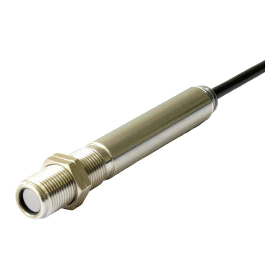
Page 5: Description
They calculate the surface temperature based on the emitted infrared energy of objects [► Basics of Infrared Thermometry]. The sensor housing of the optris CS is made of stainless steel (IP63) and contains the complete sensor electronics. The optris CS has a fixed mounted connection cable. -
Page 6: Cautions
USB kit (USB adapter cable + software). Vcc adjust: inactive If the unit is supplied together with the USB-kit the Signal processing: Hold mode: output is already preset to digital communication Calibration: Gain 1,000/ Offset 0,0 (bidirectional). Failsafe: inactive optris CS – E2010-12-A... - Page 7 45 °C 12 V 50 °C 13 V 55 °C 14 V 60 °C 15 V 65 °C 16 V 70 °C 17 V 75 °C 18 V 80 °C 19 V 85 °C 20 V optris CS – E2010-12-A...
-
Page 8: Technical Data
Weight 58 g Cable length 1 m (standard), 3 m, 8 m, 15 m Cable diameter 4,3 mm Vibration IEC 68-2-6: 3G, 11 – 200 Hz, any axis Shock IEC 68-2-27: 50G, 11 ms, any axis optris CS – E2010-12-A... -
Page 9: Electrical Specifications
alarm indication (threshold independent from alarm outputs) automatic aiming support self diagnostics temperature code indication Vcc adjust mode 10 adjustable emissivity and alarm values by variation of supply voltage/ Service mode for analog output optris CS – E2010-12-A... - Page 10 500 mA if the mV output is not used white Power supply yellow OUT Analog output/ TxD (5 V)/ Alarm output green IN/ OUT Analog input/ RxD (5 V)/ Open collector output brown Ground () black Shield optris CS – E2010-12-A...
-
Page 11: Measurement Specifications
Software (optional) CompactConnect at ambient temperature 235 °C and object temperatures >0 °C for ambient temperatures <18 °C and >28 °C at time constant ≥100 ms with smart averaging and an object temperature of 25 °C optris CS – E2010-12-A... -
Page 12: Optical Charts
Consequently, the spot should at all times have at least the same size like the object or should be smaller than that. Optical chart CS (15:1) with CF-lens (0,8 mm@ 10 mm) optris CS – E2010-12-A... -
Page 13: Close Focus Optics
CF-lens [ACCTCF] Laminar air purge with integrated CF-lens [ACCTAPLCF] If the CF-lens is used, the transmission has to be set to 0,78. To change this value the optional USB-Kit (including CompactConnect software) is necessary. optris CS – E2010-12-A... -
Page 14: Led Functions
This works also if the sensor is aimed at a new object (with probably colder temperature). After expiration of a certain reset time (default setting: 10s) the sensor will adjust the threshold level for activation of the LED new. optris CS – E2010-12-A... -
Page 15: Self Diagnostic
Out of measuring range: The object temperature is out of measuring range. Not stable: The internal temperature probes have detected an unequally internal temperature of the CS. Alarm fault: Current through the switching transistor of the open-collector output is too high. optris CS – E2010-12-A... -
Page 16: Temperature Code Indication
31 °C 3-times long flashing indicates and afterwards 1-time short flashing indicates 8 °C 10-times long flashing indicates and afterwards 8-times short flashing indicates 20 °C 2-times long flashing indicates and afterwards 10-times short flashing indicates optris CS – E2010-12-A... -
Page 17: Installation
The CS is equipped with a metric M12x1 thread and can be installed either directly via the sensor thread or with the help of the both hex nuts (standard) to the mounting bracket available. For an exact aiming of the sensor to an object the LED function ► Automatic Aiming Support can be used. optris CS – E2010-12-A... -
Page 18: Mounting Accessories
[ACCTFB] adjustable in one axis [ACCTMB] thread, adjustable in 2 axes [ACCTMG] The Mounting fork can be combined with the Mounting bracket [ACCTFB] using the M12x1 thread. Mounting bracket, adjustable in two axes [ACCTAB] optris CS – E2010-12-A... -
Page 19: Air Purge Collars
3x5 mm with the bottom section [ACCSAP] [ACCTAPL] of the Mounting fork allows an adjustment in two axes. The needed amount of air (approx. 2...10 l/ min.) depends on the [ACCTAPL+ACCTMG] application and the installation conditions on-site. optris CS – E2010-12-A... -
Page 20: Further Accessories
If the protective window is used, the transmission has to be set to 0,83. To change this value the optional USB-Kit (including CompactConnect software) is necessary. ► All accessories can be ordered using the according part numbers in brackets [ ]. optris CS – E2010-12-A... -
Page 21: Electrical Installation
Please connect each wire of the USB adapter cable with the same coloured wire of the sensor cable by using the terminal block. Press with a screw driver as shown in the picture to loose a contact. optris CS – E2010-12-A... - Page 22 unidirectional communication (burst mode – the sensor is sending data only) Open collector output The open collector output is an additional alarm output on the CS and can control an external relay e.g. In addition the analog output can be used simultaneously. optris CS – E2010-12-A...
- Page 23 Direct connection to an RS232 interface on the computer The CS works with a UART voltage of 3,3 V. For a bidirectional RS232 connection of the sensor the following interface circuits can be used: MAX3380 or MAX3321 (manufacturer: Maxim). optris CS – E2010-12-A...
-
Page 24: Schematic Circuit Diagrams For Maintenance Appl
Schematic Circuit Diagrams for Maintenance Applications Open collector output Common power supply voltage change to adjust simultaneously for direct 24V DC signal lamp alarm levels and emissivity values [Vcc adjust mode] control optris CS – E2010-12-A... - Page 25 Simple common alarm and pre-alarm generation optris CS – E2010-12-A...
-
Page 26: Software Compactconnect
Main Features: Graphic display for temperature trends and automatic data logging for analysis and documentation Complete sensor setup and remote controlling Adjustment of signal processing functions Programming of outputs and functional inputs optris CS – E2010-12-A... -
Page 27: Communication Settings
Flow control: Protocol All sensors of the CS series are using a binary protocol. To get a fast communication the protocol has no additional overhead with CR, LR or ACK bytes. To power the sensor the control signal „DTR“ has to be set. -
Page 28: Digital Command Set
Burst string Example Complete burst string Conversion to Decimal value 2 synchronisation bytes: AAAA ------ ------ process temp [°C] = (Hex Dec(03B8)-1000)/10 = -4,8 2 bytes for each output value (hi lo) 03B8 AAAA 03B8 optris CS – E2010-12-A... -
Page 29: Basics Of Infrared Thermometry
Distance to Spot size. The spectral filter selects the wavelength range, which is relevant for the temperature measurement. The detector in cooperation with the processing electronics transforms the emitted infrared radiation into electrical signals. optris CS – E2010-12-A... -
Page 30: Emissivity
ACLSED) onto the measuring object, which covers it completely. Now set the emissivity to 0,95 and take the temperature of the sticker. Afterwards, determine the temperature of the adjacent area on the measuring object and adjust the emissivity according to the value of the temperature of the sticker. optris CS – E2010-12-A... -
Page 31: Characteristic Emissivities
temperature measuring angle geometry of the surface thickness of the material constitution of the surface (polished, oxidized, rough, sandblast) spectral range of the measurement transmissivity (e.g. with thin films) optris CS – E2010-12-A... -
Page 32: Appendix A - Emissivity Table Metals
0,7-0,9 Iron non oxidized 0,05-0,2 non oxidized 0,05 rusted 0,5-0,7 Titanium polished 0,05-0,2 oxidized 0,5-0,9 oxidized 0,5-0,6 forged, blunt Wolfram polished 0,03-0,1 Iron, casted non oxidized Zinc polished 0,02 oxidized 0,6-0,95 oxidized Lead polished 0,05-0,1 optris CS – E2010-12-A... -
Page 33: Appendix B - Emissivity Table Non Metals
Glass 0,85 Grit 0,95 Gypsum 0,8-0,95 0,98 Limestone 0,98 Paint non alkaline 0,9-0,95 Paper any color 0,95 Plastic >50 μm non transparent 0,95 Rubber 0,95 Sand Snow Soil 0,9-0,98 Textiles 0,95 Water 0,93 Wood natural 0,9-0,95 optris CS – E2010-12-A... -
Page 34: Appendix C - Smart Averaging
Therefore those peaks can only be seen with a delay on the signal output. The function Smart Averaging eliminates this disadvantage by passing those fast events without averaging directly through to the signal output. Signal graph with Smart Averaging function Signal graph without Smart Averaging function optris CS – E2010-12-A...
Need help?
Do you have a question about the CS Series and is the answer not in the manual?
Questions and answers