Table of Contents
Advertisement
Quick Links
Advertisement
Chapters
Table of Contents

Related Manuals for PCB Piezotronics IMI Sensors 603 Series


Summary of Contents for PCB Piezotronics IMI Sensors 603 Series
- Page 1 Model 603C01 603-Series, 6 channel sensor kit Installation and Operating Manual For assistance with the operation of this product, contact the PCB Piezotronics, Inc. Toll-free: 800-959-4464 24-hour SensorLine: 716-684-0001 Fax: 716-684-3823 E-mail: imi@pcb.com Web: www.imi-sensors.com...
- Page 2 Assistance is needed to safely operate equipment PCB Piezotronics is an ISO-9001 certified company whose Damage is visible or suspected calibration services are accredited by A2LA to ISO/IEC Equipment fails or malfunctions 17025, with full traceability to SI through N.I.S.T.
- Page 3 CAUTION Refers to hazards that could damage the instrument. NOTE Indicates tips, recommendations and important information. The notes simplify processes and contain additional information on particular operating steps. The following symbols may be found on the equipment described in this manual: This symbol on the unit indicates that high voltage may be present.
- Page 4 PCB工业监视和测量设备 - 中国RoHS2公布表 PCB Industrial Monitoring and Measuring Equipment - China RoHS 2 Disclosure Table 有害物质 镉 汞 铅 (Pb) 六价铬 (Cr(VI)) 多溴联苯 (PBB) 多溴二苯醚 (PBDE) 部件名称 (Hg) (Cd) 住房 PCB板 电气连接器 压电晶体 环氧 铁氟龙 电子 厚膜基板 电线 电缆 塑料 焊接...
- Page 5 Component Name Hazardous Substances Lead (Pb) Mercury (Hg) Cadmium (Cd) Chromium VI Polybrominated Polybrominated Compounds Biphenyls (PBB) Diphenyl Ethers (Cr(VI)) (PBDE) Housing PCB Board Electrical Connectors Piezoelectric Crystals Epoxy Teflon Electronics Thick Film Substrate Wires Cables Plastic Solder Copper Alloy/Brass This table is prepared in accordance with the provisions of SJ/T 11364.
- Page 6 Piezoelectric ICP® Accelerometers Operating Guide Operating Guide with Enclosed Warranty Information 3424 Walden Avenue, Depew, New York 14043-2495 Phone (716) 684-0003 Fax (716) 684-3823 Toll Free Line 1-800-959-4IMI MANUAL NUMBER: 18405 MANUAL REVISION: A ECN NUMBER: 49766...
- Page 7 General OPERATING GUIDE for use with PIEZOELECTRIC ICP® ACCELEROMETERS SPECIFICATION SHEET, INSTALLATION DRAWING AND CALIBRATION INFORMATION ENCLOSED IMI ASSUMES NO RESPONSIBILITY FOR DAMAGE CAUSED TO THIS PRODUCT AS A RESULT OF PROCEDURES THAT ARE INCONSISTENT WITH THIS OPERATING GUIDE 1.0 INTRODUCTION Congratulations on the purchase of a quality ICP®...
- Page 8 The environment of the application is a critical input voltage. Also, the diode can be changed to supply consideration during program implementation. The higher currents for driving long cable lengths. Constant sensor chosen must be capable of surviving the wide current diodes, as shown in Figure 3, should be used in range of conditions to which it is subjected;...
- Page 9 MS – Mine Safety Approved Sensors 4.1 STANDARD STUD MOUNT TO – Temperature Output Sensor This mounting technique requires smooth, flat contact surfaces for proper operation and is Note: Not all sensors are available with the optional recommended permanent and/or secure prefixes.
- Page 10 semi-permanent mounting, substitute epoxy or another METHOD 2 – Direct Adhesive Mount type of adhesive. For restrictions of space or for convenience, most sensors STEP 3: Hand-tighten the sensor/mounting stud to the (with the exception of integral stud models) can be machine, then secure the sensor with a torque wrench to adhesive-mounted directly to the machine surface.
- Page 11 ICP® accelerometers are internally amplified, two-wire accelerometers. Connections to the sensor require two leads: one for the power and signal, and the other for the common and signal return. Often, coaxial cables are used since only two conductors are needed. Coaxial cables are less expensive.
- Page 12 �� (Equation 1) exceed its maximum temperature specification. For this 10 9 max= 2������ reason, do not supply excessive current over short cable runs [ �� �� −1 ] or when testing at elevated temperatures. Where, f = maximum frequency (hertz) 5.1 CABLE CONNECTOR PROCEDURE C = cable capacitance (picofarads) Care and attention to installation is essential, as the...
- Page 13 6.0 POWERING the system still does not operate properly, consult All ICP® sensors require constant current excitation an IMI Application Engineer. for proper operation. For this reason only use approved constant-current sources. A typical system Note: Always operate the accelerometer within the schematic is shown in Figure 11.
- Page 14 Periodic recalibration may be required by plants with piezoelectric accelerometers. This method relies on strict certification and traceability requirements. It is a simple comparison to a previously calibrated always recommended that the user has the sensor accelerometer, typically referred to as a reference recalibrated periodically, particularly if the sensor standard, as shown in Figure 12.
- Page 15 ICP® sensors are two-wire sensors. They are powered with a constant current DC source. The power supply is typically 18 to 30 volts DC current limited via a constant current between 2 and 20 mA. Typical battery operated supplies offer 2mA of constant current to extend battery life while Figure 14.
- Page 16 11.0 CUSTOMER SERVICE/WARRANTY IMI, a division of PCB Piezotronics, guarantees Total Customer Satisfaction. If, at any time, for any Figure 18. DC Bias Voltage Measurement reason, you are not completely satisfied with any IMI product, IMI will repair, replace or exchange it at no charge.
- Page 18 Installation and Operating Manual This manual contains the 080A131, 603C01, 687A02 installation and operating manuals that comprise a Model 687A01 Handheld Vibration Meter Kit. For assistance with the operation of this product, contact PCB Piezotronics, Inc. Toll-free: 800-959-4464 24-hour SensorLine: 716-684-0001 Fax: 716-684-3823 E-mail: imi@pcb.com...
- Page 19 Assistance is needed to safely operate equipment PCB Piezotronics is an ISO-9001 certified company whose Damage is visible or suspected calibration services are accredited by A2LA to ISO/IEC Equipment fails or malfunctions 17025, with full traceability to SI through N.I.S.T.
- Page 20 CAUTION Refers to hazards that could damage the instrument. NOTE Indicates tips, recommendations and important information. The notes simplify processes and contain additional information on particular operating steps. The following symbols may be found on the equipment described in this manual: This symbol on the unit indicates that high voltage may be present.
- Page 21 PCB工业监视和测量设备 - 中国RoHS2公布表 PCB Industrial Monitoring and Measuring Equipment - China RoHS 2 Disclosure Table 有害物质 镉 汞 铅 (Pb) 六价铬 (Cr(VI)) 多溴联苯 (PBB) 多溴二苯醚 (PBDE) 部件名称 (Hg) (Cd) 住房 PCB板 电气连接器 压电晶体 环氧 铁氟龙 电子 厚膜基板 电线 电缆 塑料 焊接...
- Page 22 Component Name Hazardous Substances Lead (Pb) Mercury (Hg) Cadmium (Cd) Chromium VI Polybrominated Polybrominated Compounds Biphenyls (PBB) Diphenyl Ethers (Cr(VI)) (PBDE) Housing PCB Board Electrical Connectors Piezoelectric Crystals Epoxy Teflon Electronics Thick Film Substrate Wires Cables Plastic Solder Copper Alloy/Brass This table is prepared in accordance with the provisions of SJ/T 11364.
- Page 23 INDUSTRIAL MONITORING INSTRUMENTATION DIVISION The Model 687A01 & 687A02 Hand Held Vibration Meter Kits Operating Guide with Enclosed Warranty Information 3425 Walden Avenue, Depew, New York 14043-2495 Phone (716) 684-0003 Fax (716) 684-3823 Toll Free Line 1-800-959-4IMI MANUAL NUMBER: 18411 MANUAL REVISION: B ECN NUMBER: 18769...
-
Page 24: Table Of Contents
INDUSTRIAL MONITORING INSTRUMENTATION DIVISION table of contents Introduction ........................page 3 Figure 1 – Model 687A01 Hand Held Vibration Meter Kit..........page 3 Description........................page 4 Sensor – Model 603C01 ....................page 5 Headphones – Model 070A47 ..................page 5 Magnetic Mounting Base –... -
Page 25: Introduction
INDUSTRIAL MONITORING INSTRUMENTATION DIVISION introduction The Model 687A01 Hand Held Vibration Meter Kit consists of a digital vibration meter, a general purpose accelerometer, an accelerometer cable assembly, magnet, and headphones. The kit is designed for general purpose, overall vibration readings on all types of machines. When unpacking the kit, be sure to note that the following accessories are included: ... -
Page 26: Description
INDUSTRIAL MONITORING INSTRUMENTATION DIVISION description The meter provides two types of measurements — overall acceleration and overall velocity. In the velocity mode, the meter measures in the frequency range of 10 Hz to 1 kHz, and complies with ISO2954 standard. It measures overall RMS velocity to a maximum of two inches per second. -
Page 27: Sensor - Model 603C01
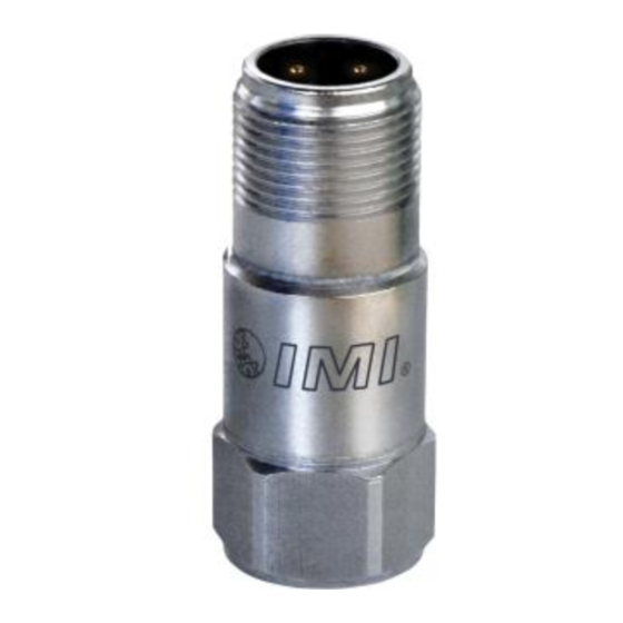
INDUSTRIAL MONITORING INSTRUMENTATION DIVISION sensor – model 603C01 The sensor supplied with the kit is a general purpose industrial accelerometer, Model 603C01. Please refer to the enclosed specifications on the 603C01 for proper operation of the sensor. headphones – model 070A47 The headphones are stereo-type with built-in, individual volume controls. - Page 28 2 – ESD sensitivity This equipment is designed with user safety in mind; however, the protection provided by the equipment may be impaired if the equipment is used in a manner not specified by PCB Piezotronics, Inc. caution 1 – ESD sensitivity Cables can kill your equipment.
- Page 29 INDUSTRIAL MONITORING INSTRUMENTATION DIVISION warranty IMI instrumentation is warranted against defective material and workmanship for 1 year unless otherwise expressly specified. Damage to instruments caused by incorrect power or misapplication, is not covered by warranty. If there are any questions regarding power, intended application, or general usage, please consult with your local sales contact or distributor.
-
Page 30: Customer Service
IMI, a division of PCB Piezotronics, guarantees Total Customer Satisfaction. If, at any time, for any reason, you are not completely satisfied with any IMI product, IMI will repair, replace, or exchange it at no charge. You may also choose, within the warranty period, to have your purchase price refunded. - Page 31 Model 687A02 Handheld Vibration Meter Installation and Operating Manual For assistance with the operation of this product, contact PCB Piezotronics, Inc. Toll-free: 800-959-4464 24-hour SensorLine: 716-684-0001 Fax: 716-684-3823 E-mail: imi@pcb.com Web: www.imi-sensors.com...
- Page 32 Assistance is needed to safely operate equipment PCB Piezotronics is an ISO-9001 certified company whose Damage is visible or suspected calibration services are accredited by A2LA to ISO/IEC Equipment fails or malfunctions 17025, with full traceability to SI through N.I.S.T.
- Page 33 CAUTION Refers to hazards that could damage the instrument. NOTE Indicates tips, recommendations and important information. The notes simplify processes and contain additional information on particular operating steps. The following symbols may be found on the equipment described in this manual: This symbol on the unit indicates that high voltage may be present.
- Page 34 PCB工业监视和测量设备 - 中国RoHS2公布表 PCB Industrial Monitoring and Measuring Equipment - China RoHS 2 Disclosure Table 有害物质 镉 汞 铅 (Pb) 六价铬 (Cr(VI)) 多溴联苯 (PBB) 多溴二苯醚 (PBDE) 部件名称 (Hg) (Cd) 住房 PCB板 电气连接器 压电晶体 环氧 铁氟龙 电子 厚膜基板 电线 电缆 塑料 焊接...
- Page 35 Component Name Hazardous Substances Lead (Pb) Mercury (Hg) Cadmium (Cd) Chromium VI Polybrominated Polybrominated Compounds Biphenyls (PBB) Diphenyl Ethers (Cr(VI)) (PBDE) Housing PCB Board Electrical Connectors Piezoelectric Crystals Epoxy Teflon Electronics Thick Film Substrate Wires Cables Plastic Solder Copper Alloy/Brass This table is prepared in accordance with the provisions of SJ/T 11364.
- Page 36 INDUSTRIAL MONITORING INSTRUMENTATION DIVISION The Model 687A01 & 687A02 Hand Held Vibration Meter Kits Operating Guide with Enclosed Warranty Information 3425 Walden Avenue, Depew, New York 14043-2495 Phone (716) 684-0003 Fax (716) 684-3823 Toll Free Line 1-800-959-4IMI MANUAL NUMBER: 18411 MANUAL REVISION: B ECN NUMBER: 18769...
- Page 37 INDUSTRIAL MONITORING INSTRUMENTATION DIVISION table of contents Introduction ........................page 3 Figure 1 – Model 687A01 Hand Held Vibration Meter Kit..........page 3 Description........................page 4 Sensor – Model 603C01 ....................page 5 Headphones – Model 070A47 ..................page 5 Magnetic Mounting Base –...
-
Page 38: Introduction
INDUSTRIAL MONITORING INSTRUMENTATION DIVISION introduction The Model 687A01 Hand Held Vibration Meter Kit consists of a digital vibration meter, a general purpose accelerometer, an accelerometer cable assembly, magnet, and headphones. The kit is designed for general purpose, overall vibration readings on all types of machines. When unpacking the kit, be sure to note that the following accessories are included: ... -
Page 39: Description
INDUSTRIAL MONITORING INSTRUMENTATION DIVISION description The meter provides two types of measurements — overall acceleration and overall velocity. In the velocity mode, the meter measures in the frequency range of 10 Hz to 1 kHz, and complies with ISO2954 standard. It measures overall RMS velocity to a maximum of two inches per second. -
Page 40: Sensor - Model 603C01
INDUSTRIAL MONITORING INSTRUMENTATION DIVISION sensor – model 603C01 The sensor supplied with the kit is a general purpose industrial accelerometer, Model 603C01. Please refer to the enclosed specifications on the 603C01 for proper operation of the sensor. headphones – model 070A47 The headphones are stereo-type with built-in, individual volume controls. - Page 41 2 – ESD sensitivity This equipment is designed with user safety in mind; however, the protection provided by the equipment may be impaired if the equipment is used in a manner not specified by PCB Piezotronics, Inc. caution 1 – ESD sensitivity Cables can kill your equipment.
- Page 42 INDUSTRIAL MONITORING INSTRUMENTATION DIVISION warranty IMI instrumentation is warranted against defective material and workmanship for 1 year unless otherwise expressly specified. Damage to instruments caused by incorrect power or misapplication, is not covered by warranty. If there are any questions regarding power, intended application, or general usage, please consult with your local sales contact or distributor.
-
Page 43: Customer Service
IMI, a division of PCB Piezotronics, guarantees Total Customer Satisfaction. If, at any time, for any reason, you are not completely satisfied with any IMI product, IMI will repair, replace, or exchange it at no charge. You may also choose, within the warranty period, to have your purchase price refunded. - Page 44 Installation and Operating Manual This manual contains the 080A131, 603C01, 687A02 installation and operating manuals that comprise a Model 687A01 Handheld Vibration Meter Kit. For assistance with the operation of this product, contact PCB Piezotronics, Inc. Toll-free: 800-959-4464 24-hour SensorLine: 716-684-0001 Fax: 716-684-3823 E-mail: imi@pcb.com...
- Page 45 Assistance is needed to safely operate equipment PCB Piezotronics is an ISO-9001 certified company whose Damage is visible or suspected calibration services are accredited by A2LA to ISO/IEC Equipment fails or malfunctions 17025, with full traceability to SI through N.I.S.T.
- Page 46 CAUTION Refers to hazards that could damage the instrument. NOTE Indicates tips, recommendations and important information. The notes simplify processes and contain additional information on particular operating steps. The following symbols may be found on the equipment described in this manual: This symbol on the unit indicates that high voltage may be present.
- Page 47 PCB工业监视和测量设备 - 中国RoHS2公布表 PCB Industrial Monitoring and Measuring Equipment - China RoHS 2 Disclosure Table 有害物质 镉 汞 铅 (Pb) 六价铬 (Cr(VI)) 多溴联苯 (PBB) 多溴二苯醚 (PBDE) 部件名称 (Hg) (Cd) 住房 PCB板 电气连接器 压电晶体 环氧 铁氟龙 电子 厚膜基板 电线 电缆 塑料 焊接...
- Page 48 Component Name Hazardous Substances Lead (Pb) Mercury (Hg) Cadmium (Cd) Chromium VI Polybrominated Polybrominated Compounds Biphenyls (PBB) Diphenyl Ethers (Cr(VI)) (PBDE) Housing PCB Board Electrical Connectors Piezoelectric Crystals Epoxy Teflon Electronics Thick Film Substrate Wires Cables Plastic Solder Copper Alloy/Brass This table is prepared in accordance with the provisions of SJ/T 11364.
- Page 49 Model Number Revision: F HANDHELD VIBRATION METER KIT 687A01 ECN #: 47534 Performance ENGLISH OPTIONAL VERSIONS Frequency Response(+10 to -20 %) 600 to 60,000 cpm 600 to 60,000 cpm Optional versions have identical specifications and accessories as listed for the standard model except where noted below.
- Page 50 Model 687A02 Handheld Vibration Meter Installation and Operating Manual For assistance with the operation of this product, contact PCB Piezotronics, Inc. Toll-free: 800-959-4464 24-hour SensorLine: 716-684-0001 Fax: 716-684-3823 E-mail: imi@pcb.com Web: www.imi-sensors.com...
- Page 51 Assistance is needed to safely operate equipment PCB Piezotronics is an ISO-9001 certified company whose Damage is visible or suspected calibration services are accredited by A2LA to ISO/IEC Equipment fails or malfunctions 17025, with full traceability to SI through N.I.S.T.
- Page 52 CAUTION Refers to hazards that could damage the instrument. NOTE Indicates tips, recommendations and important information. The notes simplify processes and contain additional information on particular operating steps. The following symbols may be found on the equipment described in this manual: This symbol on the unit indicates that high voltage may be present.
- Page 53 PCB工业监视和测量设备 - 中国RoHS2公布表 PCB Industrial Monitoring and Measuring Equipment - China RoHS 2 Disclosure Table 有害物质 镉 汞 铅 (Pb) 六价铬 (Cr(VI)) 多溴联苯 (PBB) 多溴二苯醚 (PBDE) 部件名称 (Hg) (Cd) 住房 PCB板 电气连接器 压电晶体 环氧 铁氟龙 电子 厚膜基板 电线 电缆 塑料 焊接...
- Page 54 Component Name Hazardous Substances Lead (Pb) Mercury (Hg) Cadmium (Cd) Chromium VI Polybrominated Polybrominated Compounds Biphenyls (PBB) Diphenyl Ethers (Cr(VI)) (PBDE) Housing PCB Board Electrical Connectors Piezoelectric Crystals Epoxy Teflon Electronics Thick Film Substrate Wires Cables Plastic Solder Copper Alloy/Brass This table is prepared in accordance with the provisions of SJ/T 11364.
- Page 55 Model Number Revision: C HANDHELD VIBRATION METER 687A02 ECN #: 47534 Performance ENGLISH OPTIONAL VERSIONS Frequency Response(+10 to -20 %) 600 to 60,000 cpm 600 to 60,000 cpm Optional versions have identical specifications and accessories as listed for the standard model except where noted below.
- Page 56 Model 603C01 603-Series, 6 channel sensor kit Installation and Operating Manual For assistance with the operation of this product, contact the PCB Piezotronics, Inc. Toll-free: 800-959-4464 24-hour SensorLine: 716-684-0001 Fax: 716-684-3823 E-mail: imi@pcb.com Web: www.imi-sensors.com...
- Page 57 Assistance is needed to safely operate equipment PCB Piezotronics is an ISO-9001 certified company whose Damage is visible or suspected calibration services are accredited by A2LA to ISO/IEC Equipment fails or malfunctions 17025, with full traceability to SI through N.I.S.T.
- Page 58 CAUTION Refers to hazards that could damage the instrument. NOTE Indicates tips, recommendations and important information. The notes simplify processes and contain additional information on particular operating steps. The following symbols may be found on the equipment described in this manual: This symbol on the unit indicates that high voltage may be present.
- Page 59 PCB工业监视和测量设备 - 中国RoHS2公布表 PCB Industrial Monitoring and Measuring Equipment - China RoHS 2 Disclosure Table 有害物质 镉 汞 铅 (Pb) 六价铬 (Cr(VI)) 多溴联苯 (PBB) 多溴二苯醚 (PBDE) 部件名称 (Hg) (Cd) 住房 PCB板 电气连接器 压电晶体 环氧 铁氟龙 电子 厚膜基板 电线 电缆 塑料 焊接...
- Page 60 Component Name Hazardous Substances Lead (Pb) Mercury (Hg) Cadmium (Cd) Chromium VI Polybrominated Polybrominated Compounds Biphenyls (PBB) Diphenyl Ethers (Cr(VI)) (PBDE) Housing PCB Board Electrical Connectors Piezoelectric Crystals Epoxy Teflon Electronics Thick Film Substrate Wires Cables Plastic Solder Copper Alloy/Brass This table is prepared in accordance with the provisions of SJ/T 11364.
- Page 63 Model 687A02 Handheld Vibration Meter Installation and Operating Manual For assistance with the operation of this product, contact PCB Piezotronics, Inc. Toll-free: 800-959-4464 24-hour SensorLine: 716-684-0001 Fax: 716-684-3823 E-mail: imi@pcb.com Web: www.imi-sensors.com...
- Page 64 Assistance is needed to safely operate equipment PCB Piezotronics is an ISO-9001 certified company whose Damage is visible or suspected calibration services are accredited by A2LA to ISO/IEC Equipment fails or malfunctions 17025, with full traceability to SI through N.I.S.T.
- Page 65 CAUTION Refers to hazards that could damage the instrument. NOTE Indicates tips, recommendations and important information. The notes simplify processes and contain additional information on particular operating steps. The following symbols may be found on the equipment described in this manual: This symbol on the unit indicates that high voltage may be present.
- Page 66 PCB工业监视和测量设备 - 中国RoHS2公布表 PCB Industrial Monitoring and Measuring Equipment - China RoHS 2 Disclosure Table 有害物质 镉 汞 铅 (Pb) 六价铬 (Cr(VI)) 多溴联苯 (PBB) 多溴二苯醚 (PBDE) 部件名称 (Hg) (Cd) 住房 PCB板 电气连接器 压电晶体 环氧 铁氟龙 电子 厚膜基板 电线 电缆 塑料 焊接...
- Page 67 Component Name Hazardous Substances Lead (Pb) Mercury (Hg) Cadmium (Cd) Chromium VI Polybrominated Polybrominated Compounds Biphenyls (PBB) Diphenyl Ethers (Cr(VI)) (PBDE) Housing PCB Board Electrical Connectors Piezoelectric Crystals Epoxy Teflon Electronics Thick Film Substrate Wires Cables Plastic Solder Copper Alloy/Brass This table is prepared in accordance with the provisions of SJ/T 11364.
- Page 69 Model 080A131 Curved Surface Magnet Installation and Operating Manual For assistance with the operation of this product, contact PCB Piezotronics, Inc. Toll-free: 800-959-4464 24-hour SensorLine: 716-684-0001 Fax: 716-684-3823 E-mail: imi@pcb.com Web: www.imi-sensors.com...
- Page 70 Assistance is needed to safely operate equipment PCB Piezotronics is an ISO-9001 certified company whose Damage is visible or suspected calibration services are accredited by A2LA to ISO/IEC Equipment fails or malfunctions 17025, with full traceability to SI through N.I.S.T.
- Page 71 CAUTION Refers to hazards that could damage the instrument. NOTE Indicates tips, recommendations and important information. The notes simplify processes and contain additional information on particular operating steps. The following symbols may be found on the equipment described in this manual: This symbol on the unit indicates that high voltage may be present.
- Page 72 PCB工业监视和测量设备 - 中国RoHS2公布表 PCB Industrial Monitoring and Measuring Equipment - China RoHS 2 Disclosure Table 有害物质 镉 汞 铅 (Pb) 六价铬 (Cr(VI)) 多溴联苯 (PBB) 多溴二苯醚 (PBDE) 部件名称 (Hg) (Cd) 住房 PCB板 电气连接器 压电晶体 环氧 铁氟龙 电子 厚膜基板 电线 电缆 塑料 焊接...
- Page 73 Component Name Hazardous Substances Lead (Pb) Mercury (Hg) Cadmium (Cd) Chromium VI Polybrominated Polybrominated Compounds Biphenyls (PBB) Diphenyl Ethers (Cr(VI)) (PBDE) Housing PCB Board Electrical Connectors Piezoelectric Crystals Epoxy Teflon Electronics Thick Film Substrate Wires Cables Plastic Solder Copper Alloy/Brass This table is prepared in accordance with the provisions of SJ/T 11364.
- Page 75 Model 603C01 603-Series, 6 channel sensor kit Installation and Operating Manual For assistance with the operation of this product, contact the PCB Piezotronics, Inc. Toll-free: 800-959-4464 24-hour SensorLine: 716-684-0001 Fax: 716-684-3823 E-mail: imi@pcb.com Web: www.imi-sensors.com...
- Page 76 Assistance is needed to safely operate equipment PCB Piezotronics is an ISO-9001 certified company whose Damage is visible or suspected calibration services are accredited by A2LA to ISO/IEC Equipment fails or malfunctions 17025, with full traceability to SI through N.I.S.T.
- Page 77 CAUTION Refers to hazards that could damage the instrument. NOTE Indicates tips, recommendations and important information. The notes simplify processes and contain additional information on particular operating steps. The following symbols may be found on the equipment described in this manual: This symbol on the unit indicates that high voltage may be present.
- Page 78 PCB工业监视和测量设备 - 中国RoHS2公布表 PCB Industrial Monitoring and Measuring Equipment - China RoHS 2 Disclosure Table 有害物质 镉 汞 铅 (Pb) 六价铬 (Cr(VI)) 多溴联苯 (PBB) 多溴二苯醚 (PBDE) 部件名称 (Hg) (Cd) 住房 PCB板 电气连接器 压电晶体 环氧 铁氟龙 电子 厚膜基板 电线 电缆 塑料 焊接...
- Page 79 Component Name Hazardous Substances Lead (Pb) Mercury (Hg) Cadmium (Cd) Chromium VI Polybrominated Polybrominated Compounds Biphenyls (PBB) Diphenyl Ethers (Cr(VI)) (PBDE) Housing PCB Board Electrical Connectors Piezoelectric Crystals Epoxy Teflon Electronics Thick Film Substrate Wires Cables Plastic Solder Copper Alloy/Brass This table is prepared in accordance with the provisions of SJ/T 11364.
Need help?
Do you have a question about the IMI Sensors 603 Series and is the answer not in the manual?
Questions and answers