
Subscribe to Our Youtube Channel
Related Manuals for Nautilus Hyosung MONiMAX5300


Summary of Contents for Nautilus Hyosung MONiMAX5300
- Page 1 Service Manual MONiMAX5300 System V01.00.04 (2016. 1. 25) © 2016 Nautilus Hyosung Inc. All Rights Reserved.
- Page 2 Updated all chapters by Model Name of ATM changed Update “Chapter7. SPR (Receipt Printer)” V01.00.04 2016/01/25 © 2016 Nautilus Hyosung All Rights Reserved. The content of this specification is protected by copyright laws. 2016. 1. 25. 5th Release © 2016 Nautilus Hyosung Inc. All Rights Reserved.
-
Page 3: Table Of Contents
Chapter7. Receipt Printer Appearance/Functional Diagram ····························································································· 7-1 Disassembly/Assembly Diagrams of Modules and Sensors ···························································· 7-5 Oiling Criteria ·················································································································· 7-12 Dip Switch Settings ·············································································································· 7-14 Cable Connection Diagram ··································································································· 7-15 Interface Specifications ········································································································· 7-16 © 2016 Nautilus Hyosung Inc. All Rights Reserved. - Page 4 Oiling Standard ···················································································································· 8-29 Cleaning Standard ··············································································································· 8-31 Setting Specifications ············································································································ 8-32 Cable Connection Diagram ···································································································· 8-33 Interface Specification ··········································································································· 8-34 Chapter9. Card Reader Overview ···························································································································· 9-1 Troubleshooting ·················································································································· 9-2 Preventive Maintenance ······································································································ 9-4 © 2016 Nautilus Hyosung Inc. All Rights Reserved.
- Page 5 Conventions ................................. 1-2 Abbreviations of ATM ............................1-2 Safety Precautions (English) ..........................1-4 Précautions pour la sécurité (French) ......................... 1-6 Related Documents ............................. 1-8 Overview ................................1-9 Basic Features ..............................1-10 © 2016 Nautilus Hyosung Inc. All Rights Reserved. Chapter1-I...
-
Page 6: Chapter1. Preface
▶ All measurements in this manual are in metric and U.S. standards. ▶ All information described in this manual is a licensed product of Nautilus Hyosung. Some of the information in this manual may differ according to the network processor to be connected and may be subsequently updated by the bank’s needs or the... -
Page 7: Conventions
Voice Converter for Visually Disabled Persons (ADA) Europay, Mastercard, Visa Elementary Program Encryption PIN Pad Hardware Interface International Standard Organization Journal Printer Liquid Crystal Display Magnetic Card Unit Operation Panel for Customers to Operate 2016 Nautilus Hyosung Inc. All Rights Reserved. - Page 8 Power Supply Personal Identification Number Panel Control Board Printer (mainly Receipt Printer) Switch Sensor and Indications Unit Service Provider Slip Printer (Receipt Printer) Text Terminal Unit (OPL or SPL) Vacuum Fluorescent Display © 2016 Nautilus Hyosung Inc. All Rights Reserved.
-
Page 9: Safety Precautions
4. The equipment is to be secured to the building structure before operation 5. A security container shall be permitted to optionally be provided with a secondary lock, but improper use of the secondary lock feature will reduce the security level of the ATM. 2016 Nautilus Hyosung Inc. All Rights Reserved. - Page 10 ▪ If the above-mentioned abnormalities occur, immediately turn off the power, unplug the equipment and contact the service center. ▪ If you ignore these symptoms, the equipment may catch on fire or cause electric shock. © 2016 Nautilus Hyosung Inc. All Rights Reserved.
-
Page 11: Précautions Pour La Sécurité (French)
• Ne pas retirer le couvercle. Seul le technicien d'entretien est autorisé à ouvrir le couvercle. • Ne pas toucher. Vous pouvez avoir un choc électrique. • Assurez-vous d'éteindre l'appareil lors de l'entretien de l'équipement. 2016 Nautilus Hyosung Inc. All Rights Reserved. - Page 12 2. RISQUE D'EXPLOSION SI LA BATTERIE EST REMPLACEE PAR UN TYPE INCORRECT. DISPOSER POUR UTILISATION DES BATTRIES SELON LES INSTRUCTIONS 3. POUR LES APPAREILS RACCORDES, LA PRISE DOIT ETRE INSTALLEE PRES D’EQUIPEMENT POUR ÊTRE FACILEMENT ACCESSIBLE © 2016 Nautilus Hyosung Inc. All Rights Reserved.
-
Page 13: Related Documents
▶ The related documents are listed as follows. If needed, please contact staffs of our technical support team and maintenance team. ▪ Operator Manual ▪ Installation Manual ▶ For the contact of maintenance staffs of Nautilus Hyosung, see the E-mail addresses and telephone numbers provided separately. 2016 Nautilus Hyosung Inc. All Rights Reserved. -
Page 14: Overview
▪ Specifications of expendable parts ▪ Facility specifications All information described in this manual is a licensed product of Nautilus Hyosung. It is the policy of Nautilus Hyosung to improve products as new technology, components, software, and firmware become available. Therefore Nautilus Hyosung reserves the right to change specifications without notice. -
Page 15: Basic Features
(15.1” Filter) Flicker SPR/CDU/MCR Flicker High Bright LED Guide Light PIN Light PIN PAD Light High Bright LED Speaker / Sound ADA Support Earphone Jack Customer Input Method Pin-Pad Metal Key Cap EPP 1-10 2016 Nautilus Hyosung Inc. All Rights Reserved. - Page 16 <Note!> Your MX5300 may not contain all the devices described in this section. Some devices are optional and some devices cannot be used in combination with other devices (mutually exclusive combinations). © 2016 Nautilus Hyosung Inc. All Rights Reserved. 1-11...
- Page 17 Chapter 2 System Configuration Contents About the MX5300 ............................... 2-1 The Exterior Overview ............................2-2 Hardware Configuration ............................2-3 System Block Diagram ..........................2-3 Cable Linking Diagram ..........................2-4 © 2016 Nautilus Hyosung Inc. All Rights Reserved. Chapter2-I...
-
Page 18: Chapter2. System Configuration
Allows tellers to calculate and close amount faster than the existing manual calculation. Allows easy and quick installation and maintenance. © 2016 Nautilus Hyosung Inc. All Rights Reserved. -
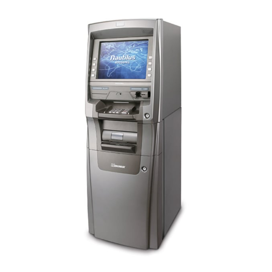
Page 19: The Exterior Overview
The fascia provides the interface between the customer and MX5300. The customer selects transactions and requests information at the fascia. Customer Customer Display with Display with Function Key touch screen Receipt Printer Slot Card Reader Entry Slot Encryption Pin Pad © 2016 Nautilus Hyosung Inc. All Rights Reserved. -
Page 20: Hardware Configuration
Service Manual Chapter2. System Configuration Hardware Configuration System Block Diagram ► System Block Diagram Sidecar PNC ► System Block Diagram of MX5300 with optional CE Sidecar PNC © 2016 Nautilus Hyosung Inc. All Rights Reserved. -
Page 21: Cable Linking Diagram
Chapter2. System Configuration Service Manual Cable Linking Diagram ► Control Equipment Linking Diagram ► Control Equipment Linking Diagram of MX5300 with optional CE © 2016 Nautilus Hyosung Inc. All Rights Reserved. - Page 22 Service Manual Chapter2. System Configuration ► Device Interface Linking Diagram ► Device Interface Linking Diagram of MX5300 with optional CE © 2016 Nautilus Hyosung Inc. All Rights Reserved.
- Page 23 Chapter2. System Configuration Service Manual ► OPL Linking Diagram ► OPL Linking Diagram of MX5300 with optional CE © 2016 Nautilus Hyosung Inc. All Rights Reserved.
- Page 24 Service Manual Chapter2. System Configuration ► Power Linking Diagram ► Power Linking Diagram of MX5300 with optional CE © 2016 Nautilus Hyosung Inc. All Rights Reserved.
- Page 25 Chapter2. System Configuration Service Manual ► Ground Cable Linking Diagram ► Ground Cable Linking Diagram of MX5300 with optional CE © 2016 Nautilus Hyosung Inc. All Rights Reserved.
- Page 26 Associated electronic boards ........................3-4 Encryption PIN Pad ............................. 3-7 Common Occurred Problem List ........................3-8 Troubleshooting ............................3-8 Panel Control Board ............................3-9 Functionality ..............................3-9 Bar Code Reader ............................... 3-10 © 2016 Nautilus Hyosung Inc. All Rights Reserved. Chapter3-I...
-
Page 27: Chapter3. User Handling Unit
(15.1” Filter) Guide Light Flicker SPR/CDU/MCR Flicker High Bright PIN Light PIN PAD Light High Bright Audio Guidance Support Speaker ADA Audio Guidance Support Ear Phone Jack Barcode Reader 2D Barcode Scanner © 2016 Nautilus Hyosung Inc. All Rights Reserved. -
Page 28: Operation Panel For Customer (Opl)
- DE (Data Enable) & H-Sync & V-Sync mode - RoHS Compliant ► General Specification Parameter Specification Unit Remarks Active Area 304.128(H) × 228.096(V) Pixel No. Pixels 1024(H) ×768(V) Pixel Pitch 0.297(H) ×0.297(V) Pixel Arrangement RGB Vertical stripe © 2016 Nautilus Hyosung Inc. All Rights Reserved. -
Page 29: Handling Precautions
- Do not re-adjust variable resistor or switch etc. - When returning the module for repair or etc., Please pack the module not to be broken. We recommend to use the original shipping packages. © 2016 Nautilus Hyosung Inc. All Rights Reserved. -
Page 30: Associated Electronic Boards
1) +12V Bypass : for +12V Inverter 2) +24V Bypass : for +24V Inverter 3) AP1501 : +5V(Max 3A) 4) RC1117-3.3V : +3.3V(Typ 1.5A), LCD Panel 5) AP1120S(Dual Regulator) : +3.3V(Typ 800mA), +1.8V(Typ 800mA) Core © 2016 Nautilus Hyosung Inc. All Rights Reserved. - Page 31 3. ODS Menu - Main Menu - Mode Change 2-digital 1-analog Exit 1 Analog: Analog Input 2 Digital: Digital Input - Bright Change Exit 1-bright 2-contrast 1 Bright: Bright Change 2 Contrast: Contrast Change © 2016 Nautilus Hyosung Inc. All Rights Reserved.
- Page 32 3 Phase : Phase Change 4 Horizontal Position: Horizontal Position Change 5 Vertical Position: Vertical Position Change - Tool Exit 1 OSD Setting: OSD Setting Change 2 Initialization: Initialization Setting (T.B.D) 3 Resolution: Resolution Change © 2016 Nautilus Hyosung Inc. All Rights Reserved.
-
Page 33: Encryption Pin Pad
Boot firmware download is Common for OPEN available for CLOSE. USB/Serial Power Connector USB EPP Serial Connector USB EPP USB Connector USB EPP Power Connector Serial EPP Serial Connector Serial EPP © 2016 Nautilus Hyosung Inc. All Rights Reserved. -
Page 34: Common Occurred Problem List
1. If LED1 is off, check the cable connection to see if the power supply is okay. 2. If LED1 is on and LED2 is off, it means EPP is in abnormal operation. Therefore, replace the EPP © 2016 Nautilus Hyosung Inc. All Rights Reserved. -
Page 35: Panel Control Board
▪ Control the POWER CONTROL signals: Power ON/OFF, AC STOP/RECOVER, Battery OFF ▪ Check SENSOR Signals: Door Sensor, Earphone insertion detect ▪ Power Distribution: Supply the Pin Pad Power. Supply the Card Reader Power PNC Board © 2016 Nautilus Hyosung Inc. All Rights Reserved. -
Page 36: Bar Code Reader
▶ This bar code reader is an automatic identification and optical device. It scans the image using CMOS image sensor and transfer the data gathered by decoding the corresponding bar code to higher device. 3-10 © 2016 Nautilus Hyosung Inc. All Rights Reserved. - Page 37 Main Board ................................4-3 Layout & Jumper Setting ..........................4-4 Optional Main Board ............................4-15 Introduction ..............................4-15 Jumper setting ............................4-18 Connection ..............................4-19 HDD ................................... 4-31 ODD ................................... 4-32 © 2016 Nautilus Hyosung Inc. All Rights Reserved. Chapter4-I...
-
Page 38: Overview
USB Hub used to communicated with some devices like cash dispenser, card reader, receipt printer, EPP. The following picture will show you the manor component and location used in Control Electronics © 2016 Nautilus Hyosung Inc. All Rights Reserved. -
Page 39: Disassembly Procedure
5. To take apart electronic board or card you want to replace, just disconnect cables or unscrew a couple of fixing screws 6. The assembly order is the opposite of the disassembling order. © 2016 Nautilus Hyosung Inc. All Rights Reserved. -
Page 40: Main Board
- Parallel port x1, Serial port (x2 for 845PA/PAP, x1 for 845GA/GAP) Multi I/O - USB 2.0 connector x2, headers x4 (connecting cable option) - Audio connector Line-in, Line-out, MIC & Game Prot header © 2016 Nautilus Hyosung Inc. All Rights Reserved. -
Page 41: Layout & Jumper Setting
Service Manual Layout & Jumper Setting ► Layout & Jumper Setting ► Jumpers Jumper Name Description CMOS RAM Clear 3-pin Block Keyboard Power On Enable/Disabled 3-pin Block CPU Frequency Select 3-pin Block © 2016 Nautilus Hyosung Inc. All Rights Reserved. - Page 42 Reset switch / Power On Button lead) Button) Wake On-LAN Headers 3-pin Block SFAN1, FAN Headers 3-pin Block SYSFAN2, CPUFAN IR infrared module Headers 5-pin Block CDIN CD Audio-In Headers 4-pin Block © 2016 Nautilus Hyosung Inc. All Rights Reserved.
- Page 43 The ATX Power Supply which fully support Pentium 4 processor must including this connector for support extra 12V voltage to maintain system power consumption. Without this connector might cause system unstable because the power supply can not provide sufficient current for system. © 2016 Nautilus Hyosung Inc. All Rights Reserved.
- Page 44 10. Floppy drive Connector (34-pin block): FDD This connector supports the provided floppy drive ribbon cable. After connecting the single plug end to motherboard, connector the two plugs at other end to the floppy drive. © 2016 Nautilus Hyosung Inc. All Rights Reserved.
- Page 45 • For performance issues, we strongly suggest you don’t install a CD-ROM or DVD- ROM drive on the same IDE channel as a hard disk. Otherwise, the system performance on this channel may drop. © 2016 Nautilus Hyosung Inc. All Rights Reserved.
- Page 46 The power LED is light on while the system power is on. Connect the power LED from the system case to this pin. 6. Power switch : PWR BTN This 2-pin connector connects to the case-mounted power switch to power ON/OFF the system. © 2016 Nautilus Hyosung Inc. All Rights Reserved.
- Page 47 You must configure the setting through the BIOS setup to use the IR function. 9. CD Audio-In Headers (4-pin): CDIN CDIN are the connectors for CD-Audio Input signal. Please connect it to CD-ROM CD-Audio output connector. 4-10 © 2016 Nautilus Hyosung Inc. All Rights Reserved.
- Page 48 Bank 0, 1 (DIMM1) DDRDDR266/DDR333 64MB1.0GB DDR SDRAM Module Bank 2, 3 (DIMM2) DDRDDR266/DDR333 64MB1.0GB DDR SDRAM Module Generally, installing DDR SDRAM modules to your motherboard is very easy, you can © 2016 Nautilus Hyosung Inc. All Rights Reserved. 4-11...
- Page 49 Some expansion cards need an IRQ to operate. Generally, an IRQ must exclusively assign to one use. In a standard design, there are 16 IRQs available but most of them are already in use. 4-12 © 2016 Nautilus Hyosung Inc. All Rights Reserved.
- Page 50 If using PCI cards on shared slots, make sure that the drivers support “Shared IRQ” or that the cards don’t need IRQ assignments. Conflicts will arise between the two PCI groups that will make the system unstable or cards inoperable. © 2016 Nautilus Hyosung Inc. All Rights Reserved. 4-13...
- Page 51 AGP 2X (3.3V) or AGP 4X (1.5V). But the factory default setting is 2X (3.3V). If you install this AGP card in motherboard without change the jumper setting to 4X (1.5V), it will burn the motherboard. 4-14 © 2016 Nautilus Hyosung Inc. All Rights Reserved.
-
Page 52: Optional Main Board
PS/2 type keyboard and mouse Watchdog timer software programmable USB 2.0 Support up to 6 ports Video output Support Dual Independent display (CRT + DVI only) Ethernet Single 10/100Mbps Realtek RTL8100C AC’97 ALC65 Audio © 2016 Nautilus Hyosung Inc. All Rights Reserved. 4-15... - Page 53 Chapter4. Control Electronics Service Manual ► Block Diagram 4-16 © 2016 Nautilus Hyosung Inc. All Rights Reserved.
- Page 54 Service Manual Chapter4. Control Electronics © 2016 Nautilus Hyosung Inc. All Rights Reserved. 4-17...
-
Page 55: Jumper Setting
► The Function Pin Setting of UART (COM1~COM4) In order to set the valid function of UART(COM1~COM4), you should install these jumpers to correct location. The connector JCOM345678 combines the pins from COM3 to COM8. 4-18 © 2016 Nautilus Hyosung Inc. All Rights Reserved. -
Page 56: Connection
SYS_FAN1 S_ATA1 Serial ATA Connectors S_ATA2 Digital I/O Connector DIO1 F_PANEL1 PWR & RST Buttons and Indicators CD_IN1 Internal CD Audio Input LINE_OUT1 Internal Audio Output CPU12V1 ATX-12V CPU Power Source © 2016 Nautilus Hyosung Inc. All Rights Reserved. 4-19... - Page 57 Two 6-pin mini DIN connectors (KB/MS1) is located on the mounting bracket for easy connection to a keyboard or a PS/2 mouse. ► VGA Connector The product has a built-in 15-pin VGA connector directly connects to your CRT monitor. 4-20 © 2016 Nautilus Hyosung Inc. All Rights Reserved.
- Page 58 The product provide 4 external Universal Serial Bus(USB) port connectors for USB peripherals. It is also equipped with one built-in 10/100Mbps Ethernet controllers. You can connect it to your LAN through RJ45 LAN connectors. © 2016 Nautilus Hyosung Inc. All Rights Reserved. 4-21...
- Page 59 Chapter4. Control Electronics Service Manual ► Audio Input and Output Connector The product is equipped with high quality AC97 compatible codec to provide a complete integrated audio solution for system. 4-22 © 2016 Nautilus Hyosung Inc. All Rights Reserved.
- Page 60 Service Manual Chapter4. Control Electronics ►IDE Disk Drive Connector You can attach the IDE(Integrated Device Electronics) hard disk drives on one channels. The connectors support Ultra-DMA100 IDE devices © 2016 Nautilus Hyosung Inc. All Rights Reserved. 4-23...
- Page 61 Chapter4. Control Electronics Service Manual ► Floppy Disk Drive Connector The product board is equipped with a 34-pin daisy-chain drive connector cable. 4-24 © 2016 Nautilus Hyosung Inc. All Rights Reserved.
- Page 62 Service Manual Chapter4. Control Electronics ► Internal Serial Port Connector The product offers eight internal high speeds UART, accessed through the 10-pin cable connector or 60-pin cable connector. © 2016 Nautilus Hyosung Inc. All Rights Reserved. 4-25...
- Page 63 Chapter4. Control Electronics Service Manual 4-26 © 2016 Nautilus Hyosung Inc. All Rights Reserved.
- Page 64 Shift Keyed IR (ASKIR) interface. If you want to use the IrDA port, you have to configure SIR or ASKIR model in the BIOS under Peripheral Setup COM2. Then the normal RS- 232 COM 2 will be disabled. © 2016 Nautilus Hyosung Inc. All Rights Reserved. 4-27...
- Page 65 BIOS can recognize the fan speed. Please note that only specified fan can issue the rotation signals. ► Serial ATA Connectors The product provides 2 Serial ATA ports to connect with Serial ATA devices. 4-28 © 2016 Nautilus Hyosung Inc. All Rights Reserved.
- Page 66 There are several PWR & RST buttons and indicators for monitoring and controlling your CPU board. The product provides you with digital input / output. These pins can be programmed by user. ► Internal Audio Source Connectors The internal © 2016 Nautilus Hyosung Inc. All Rights Reserved. 4-29...
- Page 67 These connectors are for an ATX power supply plugs. The power supply plugs are designed to fit these connectors in only one orientation. Find the proper orientation and push down firmly until the connectors completely fit. 20 11 10 1 4-30 © 2016 Nautilus Hyosung Inc. All Rights Reserved.
-
Page 68: Hdd
► It is a storage device of CE module within ATM System (generic auxiliary storage device) to take installation CD to allow for OS and AP program installation. The figure below is a sample picture of HDD. © 2016 Nautilus Hyosung Inc. All Rights Reserved. 4-31... -
Page 69: Odd
► It is a storage device of CE module within ATM System (generic auxiliary storage device) to take installation CD to allow for OS and AP program installation. The figure below is a sample picture of ODD. 4-32 © 2016 Nautilus Hyosung Inc. All Rights Reserved. - Page 70 Chapter 5 Power Supply Contents Overview ................................5-1 Specification ................................. 5-1 © 2016 Nautilus Hyosung Inc. All Rights Reserved. Chapter5-I...
-
Page 71: Chapter5. Power Supply
INPUT UNDER VOLTAGE 110Vac, 220Vac : 50% ~ 70% (Normal Watt : PROTECTION 150W) FREQUENCY 47~63Hz(NORMAL:50/60Hz) DISTORTION EFFICIENCY 65% MIN(at MAX LOAD) HOLD-UP TIME 16.7ms MIN INRUSH CURRENT 60A MAX LEAKAGE CURRENT 3.5mA MAX © 2016 Nautilus Hyosung Inc. All Rights Reserved. - Page 72 Unit Channel +5VSB(Stand- BATTERY BATTERY (Charge) (Discharge) Voltage 4.75 ~ 5.25 27 ± 10% 25.2 ~ 22.8 Current 0 ~ 0.5 Method SWITCHING SWITCHING BATTERY MODE Ripple mVp-p Noise Vp-p Shoot ±3 © 2016 Nautilus Hyosung Inc. All Rights Reserved.
- Page 73 - Output shall not exceed 144W(+3.3V,+5V,+12V,-5V,-12V outputs’ Power is 144W) 4) Aging test shall be tested on condition of total power 221W - Or tested by connecting up Main Board System(945M/B). ► Signal Output Specification © 2016 Nautilus Hyosung Inc. All Rights Reserved.
- Page 74 +24V 18AWG/UL1007 WHITE +12V 18AWG/UL1007 GREEN MOLEX 18AWG/UL1007 BLACK (5569-08P) -12V 18AWG/UL1007 BLUE +24V 18AWG/UL1007 WHITE 18AWG/UL1007 BLACK 18AWG/UL1007 BLACK 4. CDU Division PIN No. Configuration Size Color Remark 18AWG/UL1007 18AWG/UL1007 BLACK © 2016 Nautilus Hyosung Inc. All Rights Reserved.
- Page 75 PIN No. Configuration Size Color Remark +3.3V 16AWG/UL1007 BROWN MOLEX 16AWG/UL1007 BLACK (5559-02P) 9. Battery Division PIN No. Configuration Size Color Remark BATTERY(+) 18AWG/UL1015 WHITE BATTERY BECH-N 18AWG/UL1015 BLACK (1-480703- BATTERY(-) 18AWG/UL1015 BLACK © 2016 Nautilus Hyosung Inc. All Rights Reserved.
- Page 76 Active of this signal means LOW-N battery should Replaced, display of error code required P OFF-N 0V(OPEN) Stand-by switch go to off position <Note!> 1) CABLE UL1007 22AWG 2) CONNECTOR MOLEX 5559-12P © 2016 Nautilus Hyosung Inc. All Rights Reserved.
- Page 77 Chapter 6 Safe Unit Contents Dial Lock ................................6-1 How to open the dial lock ..........................6-1 Optional Lock 1: Electronic Lock ......................... 6-4 Optional Lock 2: Cencon Lock ..........................6-6 © 2016 Nautilus Hyosung Inc. All Rights Reserved. Chapter6-I...
-
Page 78: Chapter6. Safe Unit
5 Turn the dial to the RIGHT. When the lock is open, the dial will stop between 90 and 0. To lock the combination lock, turn the dial four complete rotations to the LEFT. © 2016 Nautilus Hyosung Inc. All Rights Reserved. - Page 79 When testing you must make the final turn to the stopping point (90 - 0) to be certain the bolt retracts. CAUTION! After changing the combination always dial the new combination and retract the combination lock bolt several times before shutting and locking the vault or safe door. © 2016 Nautilus Hyosung Inc. All Rights Reserved.
- Page 80 (bolts extended) position before turning the dial to extend the lock bolt. If you notice any resistance DO NOT force the dial to turn. Do not turn the safe handle to the locked position with the safe door open as this may damage the safe. © 2016 Nautilus Hyosung Inc. All Rights Reserved.
-
Page 81: Optional Lock 1
The replacement of batteries at least once annually is recommended. <Note!> If battery is depleted and will not allow lock to open, follow instructions below. Lock contains a non-volatile memory, even with batteries removed the lock will retain all programming. © 2016 Nautilus Hyosung Inc. All Rights Reserved. - Page 82 5. Carefully position the keypad over the mounting screws and slide the keypad Housing down. Ensure there are no wires or cables trapped between the input pad and the safe door. Pinched cables can result in a short circuit. © 2016 Nautilus Hyosung Inc. All Rights Reserved.
-
Page 83: Optional Lock 2
CW = Clockwise; CCW = Counter Clockwise 2. Enter the factory combination of 50-25-50 by sequentially pressing those six buttons. The LCD will display the entered number. © 2016 Nautilus Hyosung Inc. All Rights Reserved. - Page 84 If the bolt does not retract, you can be assured the lock is secured. Helpful Hint: At any point while entering the combination during an opening sequence, if you notice that an incorrect number was pressed on the keypad, you may clear the © 2016 Nautilus Hyosung Inc. All Rights Reserved.
- Page 85 The best thing to do in analyzing the lock level is to write down the entire string and then pick out the portions of it that are significant to you, or if you are experiencing a problem with the lock, report the entire string to the Tech Support group. © 2016 Nautilus Hyosung Inc. All Rights Reserved.
- Page 86 Record the new combination and store it in a secure place. If this combination is lost or forgotten, there is no alternate way to open the lock. 12. POC Remove Change Key EOP Remove the change key. EOP (End Operation) is displayed. © 2016 Nautilus Hyosung Inc. All Rights Reserved.
- Page 87 15. OPr Retract Bolt Turn the Dial to the right (CW) to retract the bolt. 16. Close Door 17. Extend Bolt Turn the Dial to the left (CCW) to extend the bolt. 6-10 © 2016 Nautilus Hyosung Inc. All Rights Reserved.
- Page 88 Oiling Criteria for Each Module ........................7-13 DIP Switch Settings ............................7-14 Cable Connection Diagram ..........................7-15 Interface Specifications ............................7-16 Upper Unit Interface ........................... 7-16 Interface Connector Diagram ........................7-16 Interface Connector ............................ 7-17 © 2016 Nautilus Hyosung Inc. All Rights Reserved. Chapter7-I...
-
Page 89: Appearance/Functional Diagram
Service Manual Chapter7. SPR (Receipt Printer) Appearance/ Functional Diagram Appearance & Dimension ► Appearance ► Dimensions © 2016 Nautilus Hyosung Inc. All Rights Reserved. -
Page 90: Diagram For Sensors And Electromagnetic Components
Diagram for Sensors and Electromagnetic Components ► Sensors and electromagnetic components of Receipt Printer are arranged as shown in the following figure. Table shows names and description of the sensors and the parts. © 2016 Nautilus Hyosung Inc. All Rights Reserved. - Page 91 :OFF paper Paper Returning Returns the DEFAULT Internal Motor Motor paper :OFF Drives the DEFAULT Cutter Motor Internal Motor cutter :OFF Returns the DEFAULT Returning Motor PM20S paper :OFF © 2016 Nautilus Hyosung Inc. All Rights Reserved.
-
Page 92: Block Diagram
MOTOR 232C DRV 232C DRV L293DD L293DD MAX232 MAX232 I/O Port I/O Port LM339 LM339 SENSOR SENSOR DIP S/W DIP S/W 회수 회수 WITHDRAWAL 2803 2803 MOTOR MOTOR SMA4032 SMA4032 SOLENOID SOLENOID © 2016 Nautilus Hyosung Inc. All Rights Reserved. -
Page 93: Disassembly/Assembly Diagrams Of Modules And Sensors
2. Pull out the TPH cable and the sensor cable from the main PCBA. 3. Remove the screws connected to the frame left/right (M3, 4 places) to remove the TPH support assembly. © 2016 Nautilus Hyosung Inc. All Rights Reserved. - Page 94 ► Disassembling MS3 (Jam Sensor) 1. Remove the screw (M3, 1 place) at the bottom of the guide outlet assembly from the removed TPH support assembly to remove the MS3 (Jam sensor). © 2016 Nautilus Hyosung Inc. All Rights Reserved.
- Page 95 ► Disassembling MM3 (Returning Motor) 1. Remove the screws (M2, 2 places) at the bottom of the guide outlet assembly from the removed TPH support assembly to remove the MM3 (Returning motor). © 2016 Nautilus Hyosung Inc. All Rights Reserved.
- Page 96 1. Remove the screws from the TPH support assembly (Guide outlet pivot, M3, 2 places) to remove the guide outlet assembly. 2. Remove the screws that fasten the TPH and bracket (M3, 4 places) to remove the TPH. © 2016 Nautilus Hyosung Inc. All Rights Reserved.
- Page 97 4. Remove the special screws (M3, 2 places) that are the upper/lower pivot of the base assembly to remove the upper base bracket. Then, remove the BH screws (M3, 4 places) to remove the main PCBA. © 2016 Nautilus Hyosung Inc. All Rights Reserved.
- Page 98 Chapter7. SPR (Receipt Printer) Service Manual ► Disassembling Bracket Tension Assembly 1. Remove the screws (M3, 2 places) that are connected to the base assembly to remove the assembly and bracket tension 7-10 © 2016 Nautilus Hyosung Inc. All Rights Reserved.
- Page 99 1. Remove the next bolt (M3, 1 place) from the base bracket assembly and lift up the upper bracket. 2. Plug out the MS1 cable from the main PCBA. 3. Remove the screw that connects the frame right and the end sensor assembly to remove the MS1. © 2016 Nautilus Hyosung Inc. All Rights Reserved. 7-11...
-
Page 100: Oiling Criteria
- Be sure that lubricant does not contaminate micro switch, sensor, timing pulley, timing belt, package, printing head or magnetic head. 7-12 © 2016 Nautilus Hyosung Inc. All Rights Reserved. -
Page 101: Oiling Criteria For Each Module
1. Apply the grease evenly all over the gears. Oiling Lubricant Part Name Amount Interval Position Type Roller Gear Gear Blade Grease Initial Oiling Idle Gear Gear Blade Grease Initial Oiling © 2016 Nautilus Hyosung Inc. All Rights Reserved. 7-13... -
Page 102: Dip Switch Settings
<Note!> DIP S/W setting after turning on the Receipt Printer P/S will not be recognized. (Turn on and off the Receipt Printer P/S or reset it after setting the DIP S/W) 7-14 © 2016 Nautilus Hyosung Inc. All Rights Reserved. -
Page 103: Cable Connection Diagram
Service Manual Chapter7. SPR (Receipt Printer) Cable Connection Diagram ► Receipt Printer Cable Connection Diagram Residual Transport Jam Sensor Detection Sensor Motor I/F (MS3) (MS7) (MM3) END Detection Sensor (MS1) © 2016 Nautilus Hyosung Inc. All Rights Reserved. 7-15... -
Page 104: Interface Specifications
3. CPU Serial I/F Port: Connect to the upper unit (P3.0 RxD, P3.1 TxD) 4. I/F Connector (P1) - Manufacturer: AMP - Model Name: RJ45-8P ► PIN Specifications CONFIG 1,4,6,7,8 Interface Connector Diagram ► Receipt Printer I/F Connector Diagram 7-16 © 2016 Nautilus Hyosung Inc. All Rights Reserved. -
Page 105: Interface Connector
Print Motor & Cutter I/F Printer Head Module TPH I/F CN3_A Near End Sensor CN3_B Paper dispensing/Jam Sensor Paper Set (Paper Availability) CN3_C Detection Sensor Power I/F Host I/F Paper Dispensing Motor DIP S/W © 2016 Nautilus Hyosung Inc. All Rights Reserved. 7-17... - Page 106 Cassette Guide Adjustment for Multiple Denominations ................8-26 Oiling Standard ..............................8-29 Cleaning Standard ............................. 8-31 Setting Specifications............................8-32 Dip S/W Specifications ..........................8-32 Cable Connection Diagram ..........................8-33 Main B/D ..............................8-33 Interface Specifications ............................8-34 © 2016 Nautilus Hyosung Inc. All Rights Reserved. Chapter8-I...
-
Page 107: Appearance/Functional Diagram
Service Manual Chapter8. CDU Appearance/Functional Diagram ► CDU for Business Hour-MX5300 The following figures show the three sectional diagrams of the CDU. CDU is 775.20mm high and 468.10 mm wide. © 2016 Nautilus Hyosung Inc. All Rights Reserved. - Page 108 Chapter8. CDU Service Manual ► CDU for Level 1-MX5300 The following figures show the three sectional diagrams of the CDU. CDU is 775.20mm high and 497.00 mm wide. © 2016 Nautilus Hyosung Inc. All Rights Reserved.
- Page 109 Service Manual Chapter8. CDU ► Cassette The following figures show three sectional diagrams of the cassette. Cassette is 137.50mm high, 217.00mm wide and 342mm long. © 2016 Nautilus Hyosung Inc. All Rights Reserved.
-
Page 110: Actuator Diagram
Chapter8. CDU Service Manual Actuator Diagram ► Six actuators are used. The following figure shows their location. © 2016 Nautilus Hyosung Inc. All Rights Reserved. -
Page 111: Sensor Diagram
Service Manual Chapter8. CDU Sensor Diagram ►The following figure shows the location of 34 sensors in this system. <Note!> A = Sensor far from the board. B = Sensor close to the board. © 2016 Nautilus Hyosung Inc. All Rights Reserved. -
Page 112: Unit Block Diagram
Chapter8. CDU Service Manual Unit Block Diagram ► Unit Block Diagram © 2016 Nautilus Hyosung Inc. All Rights Reserved. -
Page 113: Module And Sensor Replacement
The CDU contains a total of 34 sensors including 24 returning path sensors, 1 gate operation detection sensor, 4 cassette position detection sensors, 4 remaining note detection sensors and 1 encoder sensor. © 2016 Nautilus Hyosung Inc. All Rights Reserved. -
Page 114: Returning Path Sensor
4. From the removed sensor bracket, remove the M3 sensor screws (1 place each) of the sensor which will be replaced. 5. Replace the sensor. 6. Assemble the unit in the reverse order - 4~1. CS41BD CS41AD © 2016 Nautilus Hyosung Inc. All Rights Reserved. - Page 115 4. From the removed sensor bracket, remove the M3 sensor screws (1 place each) of the sensor which will be replaced. 5. Replace the sensor. 6. Assemble the unit in the reverse order - 4~2. © 2016 Nautilus Hyosung Inc. All Rights Reserved.
- Page 116 6. Assemble the unit in the reverse order - 4~1. Make sure to fasten the spacer and the screw end is not protruding out to the other side of the bracket. 8-10 © 2016 Nautilus Hyosung Inc. All Rights Reserved.
- Page 117 3. Remove the sensor bracket. 4. Remove the M3 sensor fastening screws from the removed sensor bracket. 5. Replace the sensor. 6. Assemble the unit in the reverse order - 4~1. © 2016 Nautilus Hyosung Inc. All Rights Reserved. 8-11...
- Page 118 6. Assemble the unit in the reverse order - 4~1. Make sure to fasten the spacer and the screw end is not protruding out to the other side of the bracket. 8-12 © 2016 Nautilus Hyosung Inc. All Rights Reserved.
- Page 119 4. Remove the M3 sensor fastening screws of the sensor to replace from the removed sensor bracket. 5. Replace the sensor. 6. Assemble the unit in the reverse order - 4~1. © 2016 Nautilus Hyosung Inc. All Rights Reserved. 8-13...
- Page 120 6. Assemble the unit in the reverse order - 4~1. Make sure to fasten the spacer and the screw end is not protruding out to the other side of the bracket. 8-14 © 2016 Nautilus Hyosung Inc. All Rights Reserved.
- Page 121 6. Assemble the unit in the reverse order - 4~1. Make sure to fasten the spacer and the screw end is not protruding out to the other side of the bracket. © 2016 Nautilus Hyosung Inc. All Rights Reserved. 8-15...
- Page 122 5. Assemble in the reverse order - 3~1. <Note!> When reassembling the CS3, pull the solenoid and adjust the detection bracket to the center of the sensor while the screw is still loose. Then, tighten the screw. 8-16 © 2016 Nautilus Hyosung Inc. All Rights Reserved.
- Page 123 4. To insert the sensor, insert the part ① first, then press part ② to lock. 5. Assemble in the reverse order - 3~1. <Note!> Make sure that the sensor always faces towards the center of the encoder shaft as shown in the following figure. © 2016 Nautilus Hyosung Inc. All Rights Reserved. 8-17...
-
Page 124: Regular Position Sensor
4. Remove the MP3 sensor screws (2 places each) from the removed sensor bracket. 5. Replace the sensor. 6. Assemble the unit in the reverse order - 4~1. <Note!> Adjust the cassette position when mounting it until a click sound is heard. 8-18 © 2016 Nautilus Hyosung Inc. All Rights Reserved. -
Page 125: Remaining Note Sensor
<Note!> Adjust the sensor by running the variable resistance so that it generates a current below 1.0V if there is cash available and above 3.0V if no cash is available. © 2016 Nautilus Hyosung Inc. All Rights Reserved. 8-19... -
Page 126: Module Replacement
3. Remove the board M3 screws (4 places in the main board, 8 places in the FM board (6 screws), Dip S/W Setting : 6-33page) 4. Replace the board. 5. Assemble in the reverse order - 4 ~ 1. 8-20 © 2016 Nautilus Hyosung Inc. All Rights Reserved. - Page 127 2. Remove the power cable from the main motor. 3. Unscrew the main motor fixing screws (M5, 4 places). 4. Remove the main motor assembly and replace it. 5. Assemble in the reverse order - 4 ~ 1. © 2016 Nautilus Hyosung Inc. All Rights Reserved. 8-21...
- Page 128 4. Unscrew the solenoid fixing screws (M4, 4 places). 5. Assemble in the reverse order – 4 ~ 1 after replacing a solenoid assembly. Adjust the gate according to the standard. 8-22 © 2016 Nautilus Hyosung Inc. All Rights Reserved.
- Page 129 2. Remove the M4 screw (1 pace) and E-Ring to remove the clutch as shown in the above figure. Then, remove the M4 screws (3 places) as shown in the figure below. © 2016 Nautilus Hyosung Inc. All Rights Reserved. 8-23...
- Page 130 <Note!> When replacing the clutch assembly, adjust the tension pulley so that belt tension is about 100g (①) to the direction and about 200g ~ 300g (②) to the direction when the timing belt is pressed by about 3mm (use the tension gauge). 8-24 © 2016 Nautilus Hyosung Inc. All Rights Reserved.
-
Page 131: Adjustment Standard
3. Adjust the solenoid position so that the gate is 1.5mm away from the shaft, when pulling the gate as shown in the right below figure. 4. Fix the solenoid M4 screws (2 places). © 2016 Nautilus Hyosung Inc. All Rights Reserved. 8-25... -
Page 132: Cassette Guide Adjustment For Multiple Denominations
Greater than 68mm GUIDE + SCR M3*11 11mm Less than71mm SPACER 2 BLACK GUIDE + SCR M3*14 Less than 68mm 14mm US Dollar SPACER 3 BLACK ►Example of the Upper Guide Setting (Dollar-66mm) 8-26 © 2016 Nautilus Hyosung Inc. All Rights Reserved. - Page 133 2. Put the hook parts of Side Guide into the holes of Guide Assembly Position, and then push it toward the pick-up assembly direction until you can see the screw hole. (see figure below) © 2016 Nautilus Hyosung Inc. All Rights Reserved. 8-27...
- Page 134 : At first, put the Side Guide under the Push-Spring and then insert the hook parts into the holes of Guide Assembly Position) 3. Assemble the SCR:PH(+):S/W:F/W(L):M3*6:W/Zn in the M3 Screw Assembly Hole 8-28 © 2016 Nautilus Hyosung Inc. All Rights Reserved.
-
Page 135: Oiling Standard
Lubricate the friction part Gate bush Mobil (1) between the bush and the gate shaft (2 places) Gear support gear Initial AlbaniaGreaseEP1 teeth surface Oiling Initial Gate spring hook AlbaniaGreaseEP1 Oiling © 2016 Nautilus Hyosung Inc. All Rights Reserved. 8-29... - Page 136 Chapter8. CDU Service Manual Gear support spring Initial AlbaniaGreaseEP1 hook Oiling Note separate Initial assembly gear teeth AlbaniaGreaseEP1 Oiling surface 8-30 © 2016 Nautilus Hyosung Inc. All Rights Reserved.
-
Page 137: Cleaning Standard
CS7 / CS17 / CS27 / CS43 dust using a CS6 / CS16 / CS26 / CS42 soft brush Guide entrance Remove the Note foreign separate Roller objects and ASS’Y dust using a soft brush © 2016 Nautilus Hyosung Inc. All Rights Reserved. 8-31... -
Page 138: Setting Specifications
#1, #6, #7 : ON Default 3 CASSETTE #2, #4, #6 : ON Default 4 CASSETTE #3, #5, #6 : ON Default ▲ Mounting 2, 3 Cassettes) ▲ Mounting 4 Cassettes 8-32 © 2016 Nautilus Hyosung Inc. All Rights Reserved. -
Page 139: Cable Connection Diagram
Sensor Unit Motor, Clutch, Solenoid Additional Sensor Unit RS-232C Comm. PLD Download POWER (VCC, +12V, +24V, GND) DIP S/W signal DC/DC Power Unit CN10 FM B/D Connection Unit CN12 2 Sheet I/F © 2016 Nautilus Hyosung Inc. All Rights Reserved. 8-33... -
Page 140: Interface Specification
► Data rate 9600BPS ►Error detection method None Parity, Framing Error, Overrun Error, Bcc Check ►Character configuration START BIT DATA 8 BITS PARITY BIT STOP BIT ► Data Protocol 1. Normal condition 8-34 © 2016 Nautilus Hyosung Inc. All Rights Reserved. - Page 141 Service Manual Chapter8. CDU 2. Abnormal condition - CDUM can respond only when the request from the GP is received © 2016 Nautilus Hyosung Inc. All Rights Reserved. 8-35...
- Page 142 Troubleshooting ..............................9-2 Troubleshooting Tools and Procedure ......................9-2 Trouble Verification ............................9-2 Field Repair Scope (Recommendation) ......................9-3 Troubleshooting Procedure ........................... 9-3 Preventive Maintenance ............................9-4 Cleaning a Card Reader ..........................9-4 © 2016 Nautilus Hyosung Inc. All Rights Reserved. Chapter9-I...
-
Page 143: Overview
Type Dip type Magnetic Stripe ISO 1, 2 Read EMV Level-1 Supported IC Card Reject Capacity 50EA 1mm/card Card Return Available for Power Failure Via system battery Anti-Skimming Enable With anti-skimming bezel © 2016 Nautilus Hyosung Inc. All Rights Reserved. -
Page 144: Troubleshooting
Copy the files to a USB drive. Send the data to Hyosung for more detailed analysis. However, in order to study the fault using the software file, the time of the fault occurrence is critical. Analysis by Hyosung on the fault may take time. © 2016 Nautilus Hyosung Inc. All Rights Reserved. -
Page 145: Field Repair Scope (Recommendation)
4. Determine if the error can be corrected in the field. 5. Take prompt measures if possible. Otherwise, replace the card reader. 6. When replacing a card reader, keep journal and log files. © 2016 Nautilus Hyosung Inc. All Rights Reserved. -
Page 146: Preventive Maintenance
1. Using canned air, dust out any accumulated debris inside the card reader. This task must be performed from the front and rear of the ATM. 2. Clean magnetic head with a cleaning card. 3. Through diagnostics, test the functionality of the card reader. © 2016 Nautilus Hyosung Inc. All Rights Reserved.
Need help?
Do you have a question about the MONiMAX5300 and is the answer not in the manual?
Questions and answers