Advertisement
Quick Links
©2004 Teleflex Incorporated (USA)
INSTALLER: THESE INSTRUCTIONS CONTAIN IMPORTANT SAFETY INFORMATION AND MUST BE FORWARDED TO THE BOAT OWNER.
These instructions describe how to install cable and drive assemblies to 'The Back Mount Rack' system helms.
BEFORE STARTING INSTALLATION: THOROUGHLY READ THESE
INSTRUCTIONS – AS WELL AS THE INSTRUCTIONS PROVIDED BY
THE ENGINE MANUFACTURER. FAILURE TO FOLLOW EITHER OF
THESE INSTRUCTIONS, OR INCORRECT ASSEMBLY, CAN RESULT
IN LOSS OF CONTROL AND CAUSE PROPERTY DAMAGE OR
INJURY.
DO NOT SUBSTITUTE PARTS FROM OTHER MANUFACTURERS,
AS THEY MAY CAUSE A SAFETY HAZARD FOR WHICH TELEFLEX
INC., USA CANNOT ACCEPT RESPONSIBILITY.
TO AVOID EXCESSIVE STEERING LOADS, AND TO GET THE BEST
STEERING PERFORMANCE, THE OUTBOARD MOTOR OR
OUTDRIVE TRIM TABS AND TILT POSITION MUST BE ADJUSTED
AS INSTRUCTED IN THE MOTOR MANUFACTURER'S OPERATION
MANUAL. FAILURE TO DO SO CAN AFFECT THE PERFORMANCE
OF THE BOAT AND ITS SAFE OPERATION.
First install the helm mounting plate (supplied with the bezel kit) to the
dashboard according to the instructions packed with the helm. If
installing the optional tilt steering system, then install the tilt mounting
plate (supplied with the helm) according to instructions packed with the
helm.
NOTE: CABLE AND DRIVE ASSEMBLIES ARE SUPPLIED
LUBRICATED AND READY FOR INSTALLATION. DO NOT ADD ANY
LUBRICANT TO EITHER ASSEMBLY. USE OF OTHER LUBRICANTS
CAN CAUSE DAMAGE TO THE STEERING CABLE, RESULTING IN
THE CABLE SEIZING OR PREMATURE WEAR. KEEP THE CABLE
AND DRIVE ASSEMBLY CLEAN DURING INSTALLATION, AS DIRT
WILL DAMAGE THE SYSTEM AND CAUSE PREMATURE WEAR.
WARNING
CABLE AND DRIVE ASSEMBLIES MUST NOT BE DISASSEMBLED
FOR ANY REASON.
FAILURE OF THE SYSTEM, WHICH COULD RESULT IN PROPERTY
DAMAGE OR PERSONAL INJURY.
6/04
Manufactured by
Teleflex, Inc. USA
640 North Lewis Road
Limerick, PA 19468 (USA)
610/495-7011
www.teleflexmarine.com
These cables are designed to work with the SH 5200 series helms only.
WARNING
REASSEMBLY MAY LEAD TO TOTAL
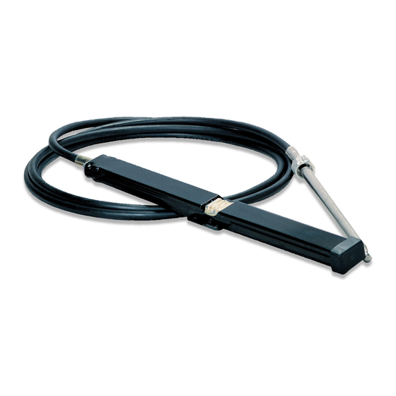
SSC 134XX/135XX/154XX
SINGLE/DUAL CABLE & DRIVE ASSEMBLY
CABLE ROUTING
Steering cables, if possible, should be routed to the starboard side of
the boat in order to balance engine torque. When routing the steering
cable, select a path with as few bends as possible and as gradual as
possible. A MINIMUM BEND RADIUS OF 8" MUST BE
MAINTAINED. WHERE CONDITIONS DICTATE, ONE BEND IN THE
CABLES IMMEDIATELY AT THE HELM CAN BE A 6' RADIUS, BUT
SHOULD BE AVOIDED, IF POSSIBLE. Sharp or frequent bends will
result in hard steering and premature cable wear. When it is necessary
to pass through a bulkhead, a 1½" diameter hole is required. Cable(s)
should be clamped or tied at regular intervals for support.
CAUTION: CABLE(S) MUST NOT BE BUNDLED TOGETHER
WITH ELECTRICAL WIRING. CABLE(S) MUST NOT REST
ON SHARP EDGES WHICH CAN CAUSE CHAFING.
BOLTS & WASHERS
FROM HELM KIT
FIGURE 1 (VIEWED FROM BACK OF HELM)
INSTALLING CABLE AND DRIVE ASSEMBLY
Place the cable and drive assembly on top of the helm unit taking care
that the pinion gear of helm unit meshes with gear teeth on rack. Turn
helm shaft to accomplish this. Fasten cable and drive assembly to rack
using (4) ¼-20 x 1" long locking patch bolts and (4) ½" OD flat washers
provided with the helm (see Figure 1). Make sure the washers are under
the head of the bolt. Tighten all 4 bolts equally and securely.
Mount the helm/cable and drive assembly to the helm (or the optional tilt)
mounting plate, following the instructions packed with the helm.
Page 1 of 2
THE BACK MOUNT RACK SYSTEM
INSTRUCTIONS
6" MINIMUM RADIUS BEND
PERMISSIBLE AT THIS POINT
(8" MINIMUM ELSEWHERE)
ONLY! (8" MIN. ELSEWHERE)
IS-SC134/135/154
Advertisement

Related Manuals for Teleflex Marine SSC 134 Series


Summary of Contents for Teleflex Marine SSC 134 Series
- Page 1 SSC 134XX/135XX/154XX Manufactured by Teleflex, Inc. USA SINGLE/DUAL CABLE & DRIVE ASSEMBLY 640 North Lewis Road THE BACK MOUNT RACK SYSTEM Limerick, PA 19468 (USA) 610/495-7011 INSTRUCTIONS www.teleflexmarine.com ©2004 Teleflex Incorporated (USA) INSTALLER: THESE INSTRUCTIONS CONTAIN IMPORTANT SAFETY INFORMATION AND MUST BE FORWARDED TO THE BOAT OWNER. These instructions describe how to install cable and drive assemblies to 'The Back Mount Rack' system helms.
- Page 2 After mounting, install the bezel and steering wheel following the To fine tune the steering, install the connection kit without adjusting the second cable tube. Turn the steering wheel so that you get a feel instructions packed with the bezel kit (ref. ISSB39526). For tilt of the load to move the engine.