Table of Contents
Advertisement
Quick Links
Advertisement
Table of Contents

Related Manuals for Bopp & Reuther Vortex VTX3 K i Ex

Summary of Contents for Bopp & Reuther Vortex VTX3 K i Ex
- Page 1 VTX3 VTX3 VTX3 VTX3 Supplementary Instructions Supplementary Instructions Supplementary Instructions Supplementary Instructions Vortex flowmeter Equipment category II 2 G, EPL Gb in protection type intrinsic safety "i" © Bopp & Reuther Messtechnik GmbH 12/2018 - Z-EN-09001-id-A Exi-Gb...
-
Page 2: Table Of Contents
CONTENTS VTX3 1 Safety instructions 1.1 General notes ........................3 1.2 EU conformity ........................3 1.3 Safety instructions......................3 2 Device description 2.1 Device description ......................4 2.2 Type code .......................... 4 2.3 Marking..........................5 2.4 Flammable products ......................7 2.5 Equipment category ...................... -
Page 3: Safety Instructions
SAFETY INSTRUCTIONS VTX3 1.1 General notes This additional instruction applies to explosion-protected versions of vortex flowmeters with protection type intrinsic safety "i", equipment category II 2 G and EPL Gb. It completes the standard manual for the non-explosion protected versions. The information given in this instruction contains only the data relevant to explosion protection. -
Page 4: Device Description
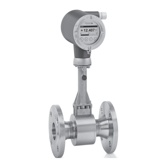
DEVICE DESCRIPTION VTX3 2.1 Device description Vortex flowmeters measure and display the flow of flammable and non-flammable gases and ® liquids. The signal converter includes either a 4...20 mA signal output with optional HART communication or a bus connection. There are bus connections available according to the FISCO model for connecting to the Foundation Fieldbus or Profibus PA. -
Page 5: Marking
DEVICE DESCRIPTION VTX3 2.3 Marking The marking of the devices in accordance with the description code is shown on the nameplates below. On both the compact devices and the remote versions, the main plate is located on the signal converter housing. On the remote versions there is an additional marking on the flow sensor. - Page 6 DEVICE DESCRIPTION VTX3 Figure 2-5: Example of the nameplates for the remote version 1 Device version VT3X W 2 Production order number 3 Serial number 4 Year of manufacture 5 Ex data according to KIWA 18 ATEX 0041X 6 Permissible ambient temperature range 7 Maximum values intrinsically safe circuits 8 Safety instructions, disposal and data matrix 9 Internet address of the manufacturer...
-
Page 7: Flammable Products
DEVICE DESCRIPTION VTX3 2.4 Flammable products Atmospheric conditions: Atmospheric conditions: Atmospheric conditions: Atmospheric conditions: The standard atmospheric conditions under which it may be assumed that Ex equipment can be operated are: • Temperature: -20...+60°C / -4...+140°F • Pressure: 80...110 kPa (0.8...1.1 bar) / 11.6...15.9 psi •... -
Page 8: Types Of Protection
DEVICE DESCRIPTION VTX3 2.6 Types of protection The marking is: ATEX II 2 G Ex ia IIC T6...T2 Gb II 2 G Ex ia IIC T6...T2 Gb II 2 G Ex ia IIC T6...T2 Gb II 2 G Ex ia IIC T6...T2 Gb (compact version, flow sensor in remote version) II 2 G Ex ia IIC T6 Gb II 2 G Ex ia IIC T6 Gb... - Page 9 DEVICE DESCRIPTION VTX3 The maximum permissible product temperatures listed in the tables are valid under the following conditions: The measuring device is installed and operated in accordance with the manufacturer's • installation instructions. It must be ensured that the flowmeter is not heated by the effects of additional heat radiation •...
- Page 10 DEVICE DESCRIPTION VTX3 Max. permissible product and ambient temperatures with signal converter or connection box mounted above the flow sensor Temperature class in °C Temperature class in °C Nominal size DN15…25 200 200 DN40…50 200 195 DN80…100 200 165 DN150...300 200 200 1 Permanent service temperature of connecting cable and cable entry min.
- Page 11 DEVICE DESCRIPTION VTX3 Max. permissible product and ambient temperatures with signal converter or connection box mounted at side or underneath the flow sensor Temperature class in °C Temperature class in °C Nominal size DN15…25 200 200 DN40…50 200 200 DN80…100 200 200 DN150...300 200 200...
- Page 12 DEVICE DESCRIPTION VTX3 Max. permissible product and ambient temperatures for devices with painted flow sensors / signal converters or connection box mounted above the flow sensor Temperature class in °C Temperature class in °C Nominal size DN15…25 DN40…50 DN80…100 DN150...300 1 Permanent service temperature of connecting cable and cable entry min.
- Page 13 DEVICE DESCRIPTION VTX3 Max. permissible product and ambient temperatures for devices with painted flow sensors / signal converters or connection box mounted at side or underneath the flow sensor Temperature class in °C Temperature class in °C Nominal size DN15…25 120 120 DN40…50 120 120...
- Page 14 DEVICE DESCRIPTION VTX3 Max. permissible product and ambient temperatures with signal converter in stainless steel (bright) or connection box in stainless steel (bright) mounted above the flow sensor Temperature class in °C Temperature class in °C Nominal size DN15…25 200 180 DN40…50 200 160 DN80…100...
- Page 15 DEVICE DESCRIPTION VTX3 Max. permissible product and ambient temperatures with signal converter in stainless steel (bright) or connection box in stainless steel (bright) mounted at side or underneath the flow sensor Temperature class in °C Temperature class in °C Nominal size DN15…25 200 200 DN40…50...
-
Page 16: Electrical Data
DEVICE DESCRIPTION VTX3 2.8 Electrical data Signal circuits Signal circuits Signal circuits Signal circuits The vortex flowmeter signal circuits may only be connected to separate, certified, intrinsically safe isolating amplifiers or zener barriers connected to separate, intrinsically safe circuits with the following maximum values per circuit: Device version Circuit... -
Page 17: Installation
INSTALLATION VTX3 3.1 Mounting Mounting and setup must be carried out according to the applicable installation standards (e.g. EN 60079-14) by qualified personnel trained in explosion protection. The information given in the manual and these instructions must always be observed. Vortex flowmeters must be installed in such a way that •... -
Page 18: Special Conditions
INSTALLATION VTX3 3.2 Special conditions Electrostatics If the installation takes place in hazardous areas of group IIC, the instructions for electrostatics Electrostatic charge must be observed. For further information refer to on page 23. Thermal and electrical data Observe the maximum ambient and product temperatures and electrical data. For further Ambient temperature / temperature classes information refer to on page 8 and refer to... -
Page 19: Electrical Connections
ELECTRICAL CONNECTIONS VTX3 4.1 General notes The separate intrinsically safe signal circuits are electrically connected in the terminal compartment of the signal converter. The circuits are designed in protection type "intrinsically safe" and galvanically isolated from ground (test voltage ≥ 500 V The intrinsically safe flow sensor circuits are connected in the connection boxes on the wall bracket and on the flow sensor. -
Page 20: Inputs / Outputs
ELECTRICAL CONNECTIONS VTX3 4.3 Inputs / Outputs The terminal assignment is described in the manual. The signal circuits of the vortex flowmeters may only be connected to certified intrinsically safe slave units or circuits. For more information refer to chapter "Electrical data". The current output, the current input and the binary output are designed for connection to a certified, intrinsically safe circuit in protection type "intrinsic safety Ex ia IIC or Ex ib IIC". - Page 21 ELECTRICAL CONNECTIONS VTX3 For remote versions with pressure sensor, the connection of the flow sensor can either be made via the PA connection in the signal converter terminal compartment or via the external PA connection. Figure 4-2: Ground connection of the remote version 1 Electrical grounding connection on the flow sensor 2 Electrical grounding connection on the housing of the signal converter 12/2018 - Z-EN-09001-id-A Exi-Gb...
-
Page 22: Flow Sensor Circuits (Remote Version Only)
ELECTRICAL CONNECTIONS VTX3 4.5 Flow sensor circuits (remote version only) Observe the following points when connecting the flow sensor to the signal converter: • Use only the supplied connecting cable (max. length 50 m / 164 ft). • Before connecting or loosening the equipotential bonding cable, ensure there are no differences in potential. -
Page 23: Operation
OPERATION VTX3 5.1 Start-up Start-up is only permitted when the measuring device: • is correctly installed in the system and connected. • has been checked for the proper state with regard to its installation and connection requirements. The operator of the system has to check prior to start-up, if the start-up was in compliance with the national regulations for checks. -
Page 24: Service
SERVICE VTX3 6.1 Maintenance Maintenance work of a safety-relevant nature within the meaning of explosion protection may only be carried out by the manufacturer, his authorised representative or under the supervision of authorised inspectors. ® Treat cover threads as necessary with the lubricating paint UNIMOLY C220 For systems in hazardous areas, regular tests are required in order to maintain the proper condition. - Page 25 SERVICE VTX3 Take special note of the following figure and: • ensure that the converter insert type is the same by checking the nameplates. • the connecting cable of the flow sensor circuits is to be laid in the cutout provided between the converter insert and housing.
-
Page 26: Notes
NOTES VTX3 www.bopp-reuther.de 12/2018 - Z-EN-09001-id-A Exi-Gb... - Page 27 NOTES VTX3 12/2018 - Z-EN-09001-id-A Exi-Gb www.bopp-reuther.de...
- Page 28 Bopp & Reuther Messtechnik GmbH Am Neuen Rheinhafen 4 67346 SPEYER, Germany Tel: +49 6232 657-0 Fax: +49 6232 657-505 Web: www.bopp-reuther.de Email: info@bopp-reuther.de...
Need help?
Do you have a question about the Vortex VTX3 K i Ex and is the answer not in the manual?
Questions and answers