Chapters
Table of Contents

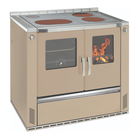
Related Manuals for Wamsler W3-90


Summary of Contents for Wamsler W3-90
- Page 1 Aufstell- und Bedienungsanleitung Instructions for Installation and Use Instructions de montage et d’utilisation Istruzioni per l’installazione e l’uso Kezelési és beállítási útmutató W3-90...
-
Page 2: Vorwort
Vorwort Sehr verehrter Kunde, wir beglückwünschen Sie zum Erwerb unseres Festbrennstoffherdes. Sie haben die richti- ge Wahl getroffen. Denn mit diesem Produkte haben Sie die Garantie für Hohe Qualität durch Verwendung bester und bewährter Materialien Funktionssicherheit durch ausgereifte Technik, die streng nach deutschen bzw. europäischen Normen geprüft ist ... -
Page 3: Table Of Contents
Inhaltsverzeichnis Vorwort ..........................2 Inhaltsverzeichnis ......................... 3 1. Installation ......................4 1.1 Sicherheitshinweise ..................... 4 1.2 Geräteaufbau ....................... 6 1.4 Aufstellraum......................8 1.5 Verbrennungsluft ....................9 1.6 Elektro-Anschluss ....................10 1.7 Sicherheitsabstände ..................11 1.8 Schornsteinanschluss ..................11 1.9 Wahl der Abgasanschlussrichtung ..............12 1.9.1 ... -
Page 4: Installation
Installation Sicherheitshinweise 1. Die Geräte sind nach DIN EN 12815 geprüft (Typenschild). 2. Bei der Aufstellung und dem abgasseitigen Anschluss sind die anwendbaren nationalen und europäischen Normen, örtliche und baurechtliche Vorschriften/Normen (z.B. DIN 18896, DIN 4705, DIN EN 13384, DIN 18160, DIN EN 1856-2, DIN EN 15287 u.a.) sowie feuerpolizeili- che Bestimmungen (z.B. - Page 5 22. Wenn Ausbesserungen oder Erneuerungen vorgenommen werden müssen, wenden Sie sich bitte rechtzeitig unter Angabe der genauen Art.Nr. und Fert.Nr. an Ihren Fachhändler. Es sind nur Original Wamsler - Ersatzteile zu verwenden. 23. Arbeiten, wie insbesondere Installation, Montage, Erstinbetriebnahme und Servicearbeiten sowie Reparaturen, dürfen nur durch einen ausgebildeten Fachbetrieb (Heizungs- oder Luf-...
-
Page 6: Geräteaufbau
Geräteaufbau W3-90 Legende: Serienzubehör: Primärluftregler - Backblech Stahlplatte - Bratrost Abgasanschlüsse - Deckelheber Anheizklappe - Russkratzer Schamotteverkleidung im Feuerraum - Schürhacken Rost - Schutzhandschuh Holzfang (Reling) - Rauchlochdeckel Seitenwand Aschekasten Sonderzubehör: 10. Sekundärluftregler - ISO Panel 11. Brennstoffwagen - Fettpfanne 12. - Page 7 Demontage/Montage der W3-90 Sockel -Blende Demontage Sockelblende zuerst leicht (ca. 1cm) noch vorne ziehen Sockelblende hinten rechts und links aushängen und leicht nach außen ziehen (schlüsselförmige Öffnung „A”) Sockelblende nach vorne abnehmen Montage Sockelblende von vorne montieren Sockelblende hinten beidseitig leicht auseinander ziehen und den Bolzen in die Öffnung einhängen...
-
Page 8: Aufstellraum
Höhenverstellung: Sockelblende entfernen durch das herausnehmen des Brennstoffwagens, sind die höheverstellbaren Füße zugänglich Mit Hilfe eines Imbus-Schlüssels (Grösse 5) oder einem Gabelschlüssels (Grösse 17mm) kann der Herd auf die gewünschte Höhe/ ins Wasser nachgestellt werden. Die passende Blende wird je nach Höhenbestellung (850 / 900 / 920 mm) mitgeliefert Vorschriften Für die Aufstellung und dem abgasseitigen Anschluss sind die anwendbaren nationalen... -
Page 9: Verbrennungsluft
Verbrennungsluft Für den Verbrennungsvorgang wird permanent Sauerstoff bzw. Luft benötigt. In der Regel reicht die vorhandene Luft im Aufstellraum aus. Bei gut abgedichteten Fenstern und Türen, Vorhandensein von mechanischen Entlüftun- gen (z.B. Küche oder Bad) oder weiteren Feuerstätten (auch Gastherme) in der Wohnung, kann die einwandfreie Luftversorgung empfindlich gestört werden. -
Page 10: Elektro-Anschluss
Wichtige Hinweise zum Thema raumluftabhängiger bzw. raumluftunabhängiger Be- trieb: (gültig für Deutschland. Stand Januar 2013) Punkt 1: Die Herde sind als raumluftabhängige Herde nach EN 12815 geprüft. Die Herde entnehmen die gesamte Verbrennungsluft über den zentralen Luftansaugstutzen aus dem Aufstellraum. An diesem Stutzen kann bauseits eine dichte Luftzuführung angeschlossen werden. -
Page 11: Sicherheitsabstände
Sicherheitsabstände Die Sicherheitsabstände von brennbaren Gegenständen und von tragenden Wänden aus Stahlbeton, sowie Stellwänden, die aus brennbaren Baustoffen hergestellt oder mit brenn- baren Baustoffen verkleidet sind, sind einzuhalten: Unterhalb der Herdplatte (von Oberkante Herd bis Fußboden) A ≥ 800 mm B ≥... -
Page 12: Wahl Der Abgasanschlussrichtung
Grad ansteigen. Rohre, die nicht wärmegeschützt oder senkrecht geführt sind, sollen nicht länger als 1 Meter sein. Es sind die Forderungen der Feuerungsverordnung (FeuVO), die jeweiligen Länderbauordnungen sowie für den Schornstein die DIN 4705, DIN EN 13384, DIN 18160 und der DIN EN 15287 zu beach- ten. -
Page 13: Elektrischer Schaltplan
Das Verbindungsstück darf nicht durch brennbare Bauteilen und Möbelteilen geführt wer- den. Bei einem seitlichen Anschluss, muss der Sicherheitsabstand zu brennbaren Bautei- len vom Hersteller des Verbindungsstückes eingehalten werden. Bild 1 1.9.3 Elektrischer Schaltplan Das Gerät darf nur von einem autorisierten Elektrofachmann gemäß den gültigen Vor- schriften und Richtlinien angeschlossen werden. -
Page 15: Brennstoffe / Einstellungen
Heizvorgang die max. Temperatur nicht erreicht werden, können die Geruchsbeläs- tigungen auch später nochmals auftreten. Maximale Aufgabemengen pro Brennstofffüllung W3-90 4,2 kg (6 - 7 Briketts) bei Nennwärmeleistung, max. 2,2 kg/h Braunkohlebriketts 4,0 kg (6 - 7 Briketts) bei Dauerbrand... -
Page 16: Verbrennungslufteinstellung
Verbrennungslufteinstellung Die Tabelle zeigt die erforderlichen Einstellungen nach Betriebsart und Brennstoff. Brenn- Primärluft- Anheizklappe- Sekundärluft- Brennstoff dauer in Stellung Stellung Stellung Anheizen Scheitholz ca. 1 Braunkohlebri- ca. 2 ketts Braunkohlebri- Dauerbrand ca. 12 ketts Außerbetriebnahme: Keinen Brennstoff mehr nachlegen Tabelle 2 Bedienung Bedienungselemente und Einstellungen 3.1.1... -
Page 17: Anheizklappe
3.1.3 Anheizklappe Zum Anzünden muss die Anheizklappe geöffnet und zum Kochen und Heizen geschlossen sein. Geschlossen (Kochen, Backen, Braten, Heizen) Offen ACHTUNG Eine offen stehende Anheizklappe während des Heizbetriebes führt zur Überhitzung des Herdes und damit zur Beschädigung von Herdteilen. Außerdem hat eine geöff- nete Anheizklappe einen erhöhten Brennstoffverbrauch zur Folge. -
Page 18: Anzünden
Anzünden Die Leistungsregulierung wird unter Beachtung der Brennstoffart je nach Zugstärke und gewünschter Heizleistung eingestellt. Mit Scheitholz insbesondere mit Weichholz, ist nur ein eingeschränkter Dauerbrand möglich. Braunkohlebriketts sind für den Dauerbrand über Nacht besonders geeignet, wenn sie auf eine satte Grundglut aufgelegt werden. Erstes Anheizen / Betrieb ... -
Page 19: Braten Und Backen Im Bratrohr
Braten und Backen im Bratrohr Der Herd ist mit einem Bratrohr aus Edelstahl mit Teleskopauszügen ausgestattet. Das Bratrohr hat eine Türe mit Glas, auf der ein Thermometer angebracht ist. Die angezeigte Temperatur dient nur als Anhaltspunkt beim Backen und Braten. Das Thermometer kann sich durch Überhitzung leicht verfärben. -
Page 20: Pflege Und Reinigung
Pflege und Reinigung 3.7.1 Gerät (Bild 4) Nach Öffnen der Heiztür ist der Rost vor jeder Brennstoffaufgabe mit Hilfe des Russkrat- zers und des Schürhakens zu reinigen. Der Aschebehälter (1) ist täglich zu entleeren. Mindestens jeden dritten Tag sollte die Schlacke vom Rost entfernt werden. -
Page 21: Lack- Und Emailoberflächen
3.7.2 Lack- und Emailoberflächen Die Pflege der äußeren Flächen ist nur bei kaltem Ofen zu empfehlen. Die lackierten Flä- chen sollten nicht gereinigt werden. Bei den emaillierten Flächen kann in besonderen Fäl- len vorher mit Wasser und Seifenlauge oder etwas Geschirrspülmittel behandelt und dann trocken gerieben werden. -
Page 22: Seitliches Schutzgitter
Vor dem Auswechseln versichern Sie sich, dass der Herd nicht benutzt wird, dass er kalt ist und dass die Glühbirne vorher nicht eingeschalten war. Den Elektroanschluss trennen und feststellen, ob wirklich keine Spannung mehr anliegt. Um die Glühbirne auszutauschen wird der Schutzdeckel entfernt, die Glühbirne ausgewechselt und der Glühbirnenschutz wieder montiert. -
Page 23: Störungsursachen Und Behebung
Störungsursachen und Behebung Ihr Herd ist nach den neuesten technischen Erkenntnissen gebaut. Dennoch können Störungen auftreten, die ihre Ursache im Schornstein, im Brennstoff oder im Abgasrohrsystem haben. Eine kurzzeitige Geruchs- und Rauchentwicklung bei der ersten Inbetriebnahme ist normal. Auf eine ausreichende Belüftung des Raumes ist zu achten. -
Page 24: Technische Daten
NOx (bezogen auf 13% O ≤ 150 mg/Nm Wirkungsgrad ≥ 80 % Netzspannung 230 V AC Glühbirne 15 W Maßzeichnung W3-90 850 (+20) 692 (+20) 900 (+20) 742 (+20) 920(+20) 762(+20) Stellfüße herausschrauben, Herdhöhe von +20 mm möglich Die angeführten Abmessungsangaben sind nur zur Information! Wir behalten uns das Recht von Konstruktionsänderungen vor, falls diese das technische Niveau erhöhen, oder die Quali-... -
Page 25: Entsorgung Des Gerätes
Wamsler Haus- und Küchentechnik GmbH • Adalperostr. 86 • • D-85737 Ismaning • Tel. +49 (0)89 / 320 84-0 • Fax +49 (0)89 / 320 84-238 info@wamsler.eu • www.wamsler.eu © Wamsler Haus- und Küchentechnik GmbH, 85737 Ismaning. Alle Rechte und Änderungen vorbehalten. Stand 04.2020... -
Page 26: Preface
Preface Dear Customer, Congratulations on your purchase of our solid fuel stove. You have made a good choice. Because this product guarantees you: High Quality thanks to use of top quality, proven materials Safe Running thanks to mature technology which has been tested for strict ad- herence to German and European standards ... -
Page 27: Table Of Contents
Table of Contents Preface ..........................26 Table of Contents ....................... 27 Safety measures ....................28 Parts ........................30 Instructions ......................31 Surrounding space .................... 32 Air supply ......................32 ... -
Page 28: Safety Measures
Installation Safety measures The stoves are tested to DIN EN 12815 (see identification plate). For installation and for flue gas connections, the requirements of the Fire Regula- tions (FeuVO in Germany) apply, as well as local building regulations such as the following technical standards DIN 4705, DIN EN 13384, DIN 18160, DIN EN 1856-2 and DIN EN 15287. - Page 29 19. If repairs or replacements are necessary, please contact your supplier with the necessary article numbers and serial numbers in good time. Only original WAMSLER replacement parts may be used. 20. Work such as installation, setup, commissioning and services, as well as repairs, must only be carried out by qualified personnel (heating system or space heating technicians).
-
Page 30: Parts
Parts W3-90 Key: Standard accessories: 1. Primary air control - Baking tray 2. Steel plate - Roasting grill 3. Flue gas connections - Lever to lift covers 4. Start damper - Soot scraper 5. Refractory clay layer in fire chamber - Fire iron 6. - Page 31 Disassembly / assembly of the W3-90 base cover dismantling 1. First pull the plinth cover slightly (approx. 1 cm) in front 2. Unhook the base panel at the rear on the right and the left side and pull it slightly outwards (key-shaped opening "A")
-
Page 32: Instructions
Height adjustment: 1. Remove the base cover 2. The height-adjustable feet are accessible by removing the fuel truck 3. With the help of an Allen key (size 5) or a fork key (size 17mm), the stove can be adjusted to the desired height / into the water 4. - Page 33 If the windows and doors are well insulated, if mechanical air extraction mechanisms are present ( e.g. in a kitchen or bathroom) or if there are other sources of fire (including gas boilers) in the home, then the supply of available air can be significantly impacted. If this is the case, the option exists to draw in air for burning directly from outdoors or from another, well-ventilated room (e.g.
-
Page 34: Electrical Connections
Important NOTES relevant to operation dependent on air supply from room or inde- pendent of air supply from room (valid for Germany – as of January 2013): The stoves have been tested under DIN EN 12815 as cookers relying on air sup- ply from room. -
Page 35: Safe Distances
Safe distances The following distances must be respected as safety margins from flammable objects and bearing walls made of reinforced concrete and partition walls made from flammable mate- rials or covered in flammable materials: Beneath the hob plate (from the top of the stove to the floor) A ≥... -
Page 36: Choice Of Flue Gas Connection Placement
The requirements of the Fire Regulations (FeuVO) apply, as well as local building regulations such as for the chimney standards DIN 4705, DIN EN 13384, DIN 18160 and DIN EN 15287. Connection pieces must be tested to DIN EN 1856-2. Measurement X (distance from flammable construction and other materials) must be as defined by the manufacturer of the connection piece. -
Page 37: Electrical Circuit Diagram
The connection piece must not be fed through flammable construction materials or furni- ture elements. When using a side connection, the safety distance from flammable ele- ments required by the manufacturer of the connection must be respected. Fig. 3 1.9.3 Electrical circuit diagram The stove may only be connected by a qualified professional electrician according to cur- rent rules and regulations. - Page 38 Action in case of chimney fire! If a chimney is not cleaned often enough, or if the wrong type of fuel is used (e.g. damp wood) or the air flow is maladjusted the chimney may catch fire. In this case close the air supply to the fire chamber and call the fire brigade.
-
Page 39: Fuels / Settings
Maximum fuel quantities per load W3-90 4,2 kg (6 - 7 briquettes) at nominal heat load Lignite briquettes... -
Page 40: Combustion Airflow Settings
Combustion airflow settings The settings must always be as shown. Primary Secondary air- Combus- Start damper Fuel airflow set- flow setting tion dura- setting ting tion in hrs Lighting Nominal heat Firewood approx. 1 load Nominal heat Lignite briquettes approx. 2 load Long-term Lignite briquettes... -
Page 41: Start Damper
3.1.3 Start damper For lighting the stove the start damper must be open and when cooking or heating it must be closed. Closed (cooking, baking, roasting, heating) Open PLEASE NOTE Leaving the start damper open when heating will cause the stove to overheat which will damage the stove and its parts. -
Page 42: Lighting
Lighting The performance control is set depending on the type of fuel as a function of the chimney draught and the desired heating level. With firewood and particularly with softwood, only a limited heating period is possible. Lignite briquettes are much better suited to burning overnight, if they are placed on top of a layer of glowing embers. -
Page 43: Closing Down
Please observe the following NOTES: Check that the start damper has been shut for at least 60 minutes. This ensures an even temperature throughout the oven. Only put in enough fuel to reach the desired tempera- ture. This temperature can then be maintained by adding small amounts of fuel during the roasting period. -
Page 44: Varnished And Enamel Surfaces
After finishing cleaning, the heating and hob plates must be replaced correctly. The clean- ing cover (4) under the oven needs to be closed tightly again. PLEASE NOTE: After every period of heating you should check the stove thoroughly. If repairs or replacements are necessary, please contact your supplier with the necessary article numbers and serial number in good time. -
Page 45: Sheet Steel
3.7.4 Sheet steel The steel sheet parts must be rubbed over with an acid-free sheet steel care product when at blood temperature. Cleaning is then done when the stove is cold. The special steel plates which radiate heat need to be taken care of regularly after each time you cook. -
Page 46: Troubleshooting
Troubleshooting Your stove has been built using modern technology. Even so, problems can arise, which may derive from the chimney, the fuel or the flue pipe system. There may briefly be smoke and an unpleasant smell the first time you use the stove: this is normal. -
Page 47: Technical Data
≤ 0.10 % Efficiency ≥ 80 % Mains current 230 V AC Bulb 15 W Dimensions W3-90 850 (+20) 692 (+20) 900 (+20) 742 (+20) 920(+20) 762(+20) screw feet can raise stove height by +20 mm Weight: Net 174 – 210 kg... - Page 48 Préface Cher client, Nous vous félicitons d’avoir fait l’acquisition de notre cuisinière à combustible solide. Vous avez fait le bon choix. Ce produit vous donne en effet la garantie d’une qualité élevée obtenue grâce à l’utilisation des matériaux les meilleurs et les mieux éprouvés, ...
- Page 49 Sommaire Installation Consignes de sécurité ..................50 Structure de l’appareil ..................52 Pièce d’emplacement ..................54 Air de combustion ....................55 Raccordements électriques ................57 Distances de sécurité ..................57 Raccordement à la cheminée ................58 Choix de la direction de l’évacuation des fumées ..........58 1.9.1 Raccordement par le haut (figure 1) ..............
-
Page 50: Installation
Installation Consignes de sécurité Les appareils ont été contrôlés selon les normes DIN EN 12815 (Plaque signalétique). Pour la mise en place des appareils et le raccordement aux cheminées d’évacuation des gaz, on devra observer les exigences énoncées par les directives concernant les appareils de chauffage (FeuFO en Allemagne) ainsi que les normes DIN 4705, DIN EN 13384, DIN 18160, DIN EN 1856-2 et DIN EN 15287. - Page 51 à votre commerçant spécialisé en lui indiquant exactement le numéro de référence et le numéro de fabrication. On ne peut utiliser que des pièces originales WAMSLER. Les travaux, tels que, en particulier, l’installation, le montage, la première mise en service, les travaux de maintenance ainsi que les réparations ne pourront être effectués que par une...
-
Page 52: Structure De L'appareil
Structure de l’appareil W3-90 Légende : Accessoires de série : 1. Réglage de l’air primaire - Plaque de four 2. Plaque d’acier - Gril 3. Raccordement pour les gaz d’évacuation - Levier de couvercle 4. Volet d’allumage - Brosse à suie 5. - Page 53 Démontage / montage du cache de fond W3-90 Démantèlement 1. Tirez d'abord le couvercle du socle légèrement (environ 1 cm) vers l'avant 2. Décrochez le panneau de base à l'arrière à droite et à gauche et tirez-le légèrement vers l'extérieur (ouverture en forme de clé "A") 3.
-
Page 54: Pièce D'emplacement
Réglage de la hauteur: 1. Retirez le cache de fond 2. Les pieds réglables en hauteur sont accessibles en retirant le camion de carburant 3. À l'aide d'une clé Allen (taille 5) ou d'une clé à fourche (taille 17 mm), le poêle peut être réglé... -
Page 55: Air De Combustion
Air de combustion De l’oxygène (de l’air) est nécessaire en permanence pour la combustion. Normalement l’air de la pièce où est placée la cuisinière suffit. L’alimentation en air peut être sérieusement perturbée si les portes et les fenêtres ferment hermétiquement, s’il existe des systèmes d’aspiration de l’air ambiant (par exemple dans la cuisine et la salle de bains), s’il existe d’autres foyers (aussi chauffe-eau et chauffage à... - Page 56 Consignes importantes concernant le fonctionnement d’appareils dépendants ou indépendants de l’air ambiant (valable pour l'Allemagne – selon la réactualisation des règlements et directives en la matière de janvier 2005) Les cuisinières ont été contrôlées selon la norme DIN EN 12815 comme cuisinières dont le fonctionnement dépend de l’air ambiant.
-
Page 57: Raccordements Électriques
Raccordements électriques Les cuisinières sont équipées d’un raccordement prévu pour l’éclairage du four. Le câble de raccordement se trouve à l’arrière de la cuisinière. Ce branchement devra être effectué par un électricien, conformément aux directives en vigueur. Tension de réseau AC 230 V Distances de sécurité... -
Page 58: Raccordement À La Cheminée
Raccordement à la cheminée La cheminée prévue pour le branchement devra résister au minimum à une température de 400 °C. TTENTION Avant de raccorder l’appareil, il est nécessaire, dans tous les cas de consulter le ramoneur responsable de la circonscription ! Les éléments de la conduite d’évacuation doivent être bien fixés les uns aux autres. -
Page 59: Raccordement Latéral (Figure 1)
1.9.2 Raccordement latéral (figure 1) Enlever la buse d’évacuation arrière (1) en dévissant les vis. Enlever le couvercle de l’habillage latéral (10) en dévissant les vis. A l’aide d’une pince coupante latérale 3x (11) découper les tôles d’isolation aux bords et les retirer. - Page 60 Mesures à prendre dans le cas d'un feu de cheminée ! Lorsque la cheminée n'a pas été suffisamment nettoyée, ou lorsqu’on emploie un combus- tible inapproprié (du bois humide, par exemple) ou bien lorsque l’air de combustion est mal réglé, un feu de cheminée peu se déclarer. Dans un tel cas fermez l’air de combustion du foyer et appelez les pompiers.
-
Page 61: Combustibles / Réglages Combustibles
à l’avenir. Quantité maximale de combustible à ne pas dépasser lors du chargement W3-90 4,2 kg (6 - 87briquettes de lignite) pour la puissance calori- fique nominale. -
Page 62: Réglage De L'air De Combustion
Réglage de l'air de combustion Les réglages doivent toujours être sur la position des marques placées sur l’appareil Durée de Réglage de Position du volet Position de l’air Combustible combustion l’air primaire d’allumage secondaire en heures Chauffer Bûches 1 env. Briquettes de lignite 2 env. -
Page 63: Volet D'allumage
3.1.3 Volet d’allumage Le volet d’allumage doit être ouvert pour l'allumage mais doit être fermé pendant le chauffage et la cuisson. Fermé (cuisson, cuire au four, rôtir, chauffer) Ouverte Attention ! Si le volet d’allumage reste constamment ouvert pendant le fonctionnement du chauffage, la cuisinière risque de surchauffer et des pièces peuvent être endomma- gées. -
Page 64: Allumer
Allumer Tout d’abord, on réglera la puissance en tenant compte du type de combustible et de la puissance de chauffage souhaitée. Les bûches, et plus particulièrement le bois tendre ne permettent qu’un feu continu limité. Les briquettes de lignites sont particulièrement bien adaptées au feu continu nocturne si elles sont placées sur une bonne couche de braises. -
Page 65: Rôtir / Faire Cuire Au Four
La table de cuisson ne doit pas être surchauffée : une surchauffe ne présente pas d’avantages pour la cuisson et endommage la cuisinière. Rôtir / faire cuire au four La cuisinière est équipée d’un four en acier spécial pourvue de rallonges télescopiques. Le compartiment four est muni d’une porte vitrée sur laquelle un thermomètre a été... -
Page 66: Nettoyage, Entretien Et Maintenance
Nettoyage, entretien et maintenance 3.7.1 Appareil (figure 4) Après avoir ouvert la porte de chargement, il est nécessaire de nettoyer la grille de tous les restes à l’aide de la brosse à suie et du tisonnier. Le bac à cendres devra être (1) vidé chaque jour. Tous les trois jours au minimum on doit enlever les scories de la grille. -
Page 67: Surface De Verre-Céramique
3.7.3 Surface de verre-céramique Nettoyez votre vitre et/ ou votre plaque de céramique avant la première utilisation à l’aide d’un chiffon humide propre. Appliquez ensuite quelques gouttes d’un produits de soin pour le verre céramique à l’aide d’un essuie-tout en papier sur la vitre / la plaque de céramique. Après avoir été... -
Page 68: Inoxydable Caillebotis
3.7.6 Inoxydable caillebotis 1. inoxydable caillebotis en acier, de levage (Figure 5) 2. Tirer vers l'avant 3. levage et Après démontage de la grille en acier inoxydable, peut le plateau de trou sous-jacente, être nettoyé. Remontage a lieu dans l'ordre inverse. Fig. -
Page 69: Causes De Perturbations, Solutions
Causes de perturbations, solutions Votre cuisinière est construite selon l’état des techniques le plus récent en la matière. Toutefois, des perturbations peuvent être provoquées par la cheminée, le combustible ou le système de tuyaux d’évacuation de gaz. Des dégagements de fumées et d’odeurs sont normaux à... -
Page 70: Caractéristiques Techniques Données Techniques
≤ 0,10 % Rendement d'exploitation ≥ 80 % Tension de réseau 230 V AC Lampe 15 W Dessins côtés W3-90 850 (+20) 692 (+20) 900 (+20) 742 (+20) 920(+20) 762(+20) Retirer les pieds réglables il est possible d’augmenter la hauteur de la cuisinière de 20 mm. - Page 71 Premessa Gentilissimo Cliente, ci complimentiamo con Lei per aver acquistato questa cucina a combustibile solido e per l’ottima scelta effettuata! Questo prodotto Le garantisce qualità elevata grazie all’utilizzo di ottimi materiali testati funzionamento sicuro grazie alle avanzate tecnologie rigorosamente testate se- condo le norme tedesche ed europee ...
-
Page 72: Indice
Indice Indice ..........................72 Installazione....................... 73 Avvertenze di sicurezza ..................73 Struttura stufa ....................75 Normative ......................76 Luogo di installazione ..................77 Aria di combustione ................... 78 Allacciamento elettrico ..................79 Distanze di sicurezza ..................80 Collegamento alla canna fumaria ..............80 Scelta della posizione dell’attacco di scarico fumi .......... -
Page 73: Installazione
Installazione Avvertenze di sicurezza 1. L’apparecchio e i suoi dispositivi sono stati testati sulla base della norma DIN EN 12815 (vedi targhetta di identificazione). 2. Per l’installazione e il collegamento del lato gas sono da rispettare la norma per gli impianti di combustione (FeuVO per Germania), i regolamenti edilizi locali, nonché... - Page 74 18. Per eventuali riparazioni o sostituzioni contattare tempestivamente il proprio rivendito- re avendo cura di comunicare l’esatto n° di articolo e di serie dell’apparecchio. Tutti i componenti dovranno essere sostituiti esclusivamente con pezzi originali WAMSLER. 19. Eventuali lavori, in particolare l’installazione, il montaggio, la prima accensione, non- ché...
-
Page 75: Struttura Stufa
Struttura stufa W3-90 Legenda: Accessori di serie: Regolatore aria primaria - Teglia da forno Piastra di acciaio - Graticola Raccordi scarico fumi - Apri-coperchi Valvola di accensione - Raschiatore per fuliggine Rivestimento in refrattario nel focolare - Attizzatoio Griglia - Guanto di protezione... - Page 76 Montaggio della copertura W3-90: Smontaggio: Tirare avanti la copertura (circa 1 cm). Tirare la parte posteriore della copertura su due lati, rimuovendo la l’apertura della copertura dal fissaggio (apertura in forma di buco della serratura) Tirare avanti la copertura per rimuoverla dall’apparecchio.
-
Page 77: Normative
É possibile aumentare l’altezza dell’apparecchio da 850mm a 900mm o da 900mm a 920mm, come segue: Rimuovere la copertura dell’apparecchio come già abbiamo spiegato. Dopo aver smontato il cassetto, abbiamo accesso ai 4 piedi per regolare l’altezza. É possibile regolare i piedi con una chiave a brugola 5 o con una chiave a bocca 17 (c) fino all’altezza necessaria. -
Page 78: Aria Di Combustione
Aria di combustione La combustione richiede sempre l’ingresso di aria e ossigeno. Solitamente è sufficiente l’aria presente nel locale di installazione. La presenza di finestre e porte chiuse ermeticamente, di ventilazioni meccaniche (ad es. in cucina o in bagno) o di altre stufe (anche caldaie a gas) nell’abitazione può disturbare in modo notevole la corretta alimentazione di aria. -
Page 79: Allacciamento Elettrico
Importanti AVVERTENZE relative al funzionamento a camera aperta o a camera sta- gna (valido per la Germania, aggiornamento risalente a gennaio 2013): Gli apparecchi sono testati come stufe a camera aperta in base alla norma DIN EN 12815. Le stufe prelevano tutta l’aria di combustione dal locale di installazione attraver- so il bocchettone di aspirazione centrale. -
Page 80: Distanze Di Sicurezza
Distanze di sicurezza Si devono rispettare le seguenti distanze dagli oggetti infiammabili e dalle pareti portanti in cemento armato, nonché da tramezzi realizzati o rivestiti in materiali infiammabili: sotto la piastra di cottura (dallo spigolo superiore fino al pavimento) A ≥ 800 mm B ≥... -
Page 81: Scelta Della Posizione Dell'attacco Di Scarico Fumi
Per il collegamento sono da rispettare la norma FeuVO per gli im- pianti di combustione, i regolamenti edilizi locali, nonché le norme DIN 4705, DIN EN 13384, 18160 e DIN EN 15287 per la canna fu- maria. I tratti di collegamento devono essere verificati secondo DIN EN 1856-2. -
Page 82: Schema Elettrico
Il tratto di collegamento non può passare attraverso elementi costruttivi o parti di mobili infiammabili. In caso di collegamento laterale, rispettare la distanza di sicurezza dagli ele- menti infiammabili indicata dal produttore del tratto di collegamento. Figura 7 1.9.3 Schema elettrico L’apparecchio può... - Page 83 Come comportarsi in caso di incendio della canna fumaria Una pulizia non completa della canna fumaria, l’utilizzo di combustibile non idoneo (per esempio legna troppo umida) o l’impostazione sbagliata dell’aria della combustione po- trebbero provocare un incendio della canna fumaria. In questo caso chiudere la presa d’aria della stufa e chiamare immediatamente i Vigili del Fuoco.
-
Page 84: Combustibili / Impostazioni
Quantità massime per ricarica di combustibile W3-90 4,2 kg (6 - 7 mattonelle) alla potenza termica nominale Mattonelle di lignite 4,0 kg (6 - 7 mattonelle) con fuoco continuo (altra impostazione, v. -
Page 85: Impostazione Aria Di Combustione
Impostazione aria di combustione La tabella mostra le impostazioni necessarie in base a tipo di funzionamento e combustibi- Aria secondaria Fuoco Valvola di Combustibile Aria primaria continuo accensione in h Riscaldamento Ceppi di legna ca. 1 Mattonelle di lignite PTN ca. -
Page 86: Valvola Di Accensione
3.1.3 Valvola di accensione La valvola deve essere aperta per l’accensione e chiusa per il riscaldamento e la cottura. Chiusa (cuocere, cuocere al forno, riscaldare) Aperta ATTENZIONE: Se la valvola di accensione rimane aperta durante il riscaldamento, può essere pro- vocato un surriscaldamento che danneggia i componenti della stufa. -
Page 87: Cucinare E Riscaldare
Accensione La regolazione della resa viene impostata tenendo conto del tipo di combustibile utilizzato in base al tiraggio e alla resa desiderata. Con i ceppi di legna, in particolare con la legna morbida, è possibile un funzionamento a fuoco continuo solo per un tempo limitato. Le mattonelle di lignite sono particolarmente idonee per un utilizzo notturno con fuoco conti- nuo, se disposte su un abbondante letto di brace. -
Page 88: Cuocere Al Forno
Cuocere al forno La cucina comprende un forno in acciaio inox con guide telescopiche. La porta del forno è in vetro con termometro integrato. La temperatura indicata serve solo come punto di riferi- mento per la cottura. Inoltre il forno è dotato di serie di una griglia e di una teglia. Si prega di osservare le presenti INDICAZIONI. -
Page 89: Manutenzione E Pulizia
Manutenzione e pulizia 3.7.1 Apparecchio (figura 4) Dopo aver aperto lo sportello e prima di ogni aggiunta di combustibile è necessario pulire la griglia mediante il raschiatore per fuliggine e l'attizzatoio. Il cassetto cenere (1) deve essere svuotato quotidianamente. Almeno una volta ogni tre giorni occorre eliminare le scorie dalla griglia. -
Page 90: Superfici In Vetroceramica
3.7.2 Superfici verniciate o smaltate La pulizia delle superfici esterne è da effettuare a stufa fredda. Pulire le superfici verniciate utilizzando solo acqua corrente (non strofinare). In casi particolari le superfici smaltate possono essere pretrattate con acqua saponata o detersivo per piatti e poi strofinate fino a completa asciugatura. -
Page 91: Decorativo Laterale
3.7.6 Decorativo laterale Sollevare il pezzo frontale (figura 5) Spingere in avanti il rivestimento decorativo Sollevare il rivestimento decorativo Rimontare il tutto in ordine ritroso Figura 5 Cause e risoluzione di anomalie Il Suo apparecchio è stato costruito in base a tecnologie d’avanguardia. Potrebbero tuttavia verificarsi delle anomalie legate alla canna fumaria, al combustibile o al sistema dei tubi di scarico. -
Page 92: Dati Tecnici
≤ 0,10 % Efficienza ≥ 80 % Tensione di rete 230 V AC Lampadine 15 W Disegno dimensionale W3-90 850 (+20) 692 (+20) 900 (+20) 742 (+20) 920 (+20) 762 (+20) Svitare i piedini, la stufa può essere alzata di 20 mm Peso: netto 174 –... -
Page 93: Előszó
Előszó Tisztelt Ügyfelünk! Gratulálunk szilárd tüzelésű tűzhelyünk megvásárlásához. Ön jól választott, mert ezzel a termékkel garantáljuk a következőket: Kiváló minőség a legjobb és bevált alapanyagok alkalmazása révén Működésbiztonság a kifejlesztett technika révén, melyet német ill. európai szabványok szerint szigorúan ellenőrzünk. Hosszú... -
Page 94: Tartalomjegyzék
Tartalomjegyzék Előszó ..........................93 Tartalomjegyzék ......................... 94 1. Beszerelés ........................95 1.1 Biztonsági figyelmeztetések ..................95 1.2 Készülék felépítése ....................97 1.3 Előírások ......................... 98 1.4 A beállítási tere ....................... 99 1.5 Égési levegő ......................100 1.6 Elektromos csatlakozás ..................102 1.7 Biztonsági távolságok ................... -
Page 95: Beszerelés
1. Beszerelés 1.1 Biztonsági figyelmeztetések A készüléket a DIN EN 12815 szerint vizsgáltuk (típustábla). A beállításhoz és a füstgáz elvezetéséhez a tüzelési rendelet, a mindenkori országos építési rend, valamint a DIN 4705, DIN EN 13384, DIN 18160, DIN EN 1856-2 és a DIN EN 15287 követelményeit kell figyelembe venni. A készülék megfelelő... - Page 96 18. Ha javítást vagy felújítást kell végezni, akkor a pontos cikkszám és gyártási szám megadása mellett időben forduljon a kereskedőhöz. Csak eredeti Wamsler-cserealkatrészeket szabad felhasználni. 19. Olyan munkákat, mint beszerelés, szerelés, első üzembe helyezés és szervizmunkák, valamint javításokat csak képzett szaküzem (fűtés vagy légfűtésszerelés) végezhet.
-
Page 97: Készülék Felépítése
1.2 Készülék felépítése W3-90 Magyarázat szériatartozékok primer-levegő szabályozó - sütőlemez tűzhelylap - sütőrostély füstgáz-csatlakozók - fedélemelő begyújtás segítő gomb - koromkaparó samottborítás a tűztérben - korlát rostély - védőkesztyű parázsfogó - füstnyílás-fedél oldalfal hamuláda Speciális tartozékok 10. szekunder-levegő szabályozó - ISO panel 11. - Page 98 W3-90 lábazat burkolat szerelése: Leszerelés: A burkolatot előre húzzuk (kb. 1 cm). A burkolatot két oldalt a hátsó részén széthúzzuk, kiakasztva a burkolat nyílását a rögzítőből.(kulcslyuk alakú nyílás) A burkolatot előre fe lé lehúzzuk a készülékről. Felszerelés: A burkolatot ráhúzzuk előlről a készülékre.
-
Page 99: Előírások
Lehetőség van a készülék magasságának növelésére 850-ről 900-ra vagy 920 mm-re, illetve 900-ról 920 mm-re az alábbiak szerint. Az előzőekben leírtak szerint eltávolítjuk a lábazat burkolatot. A fiók kiszerelése után válik hozzáférhetővé a 4db magasság állító láb, melyeket 5-ös imbusz kulcs vagy17-es villás kulcs (C) segítségével tudjuk állítani, míg a tűzhely el nem éri a kívánt magasságot. -
Page 100: Égési Levegő
1.5 Égési levegő Az égési folyamathoz folyamatosan oxigénre ill. levegőre van szükség. Rendszerint elegendő a beállítás terének levegője. Jól letömített ablakok és ajtók, a lakásban lévő mechanikus légtelenítők (pl. konyhában) vagy más tűzhelyek (gázkályhák is) a kifogástalan levegőellátást jelentősen zavarhatják. Ha ez bekövetkezik, akkor fennáll annak a lehetősége, hogy az égési levegőt közvetlenül kívülről, vagy egy másik, eléggé... - Page 101 Helyiség levegőjétől függő illetve független üzemeltetésre vonatkozó fontos figyelmeztetések: (érvényes Németországra. 2013. januári állapot) 1. pont: A tűzhelyeket helyiség levegőjétől függő tűzhelyként a DIN EN 12815 szerint vizsgálták. A tűzhelyek az egész égési levegőt a központi légszívó csonkon keresztül a beállítás teréből nyerik.
-
Page 102: Elektromos Csatlakozás
1.6 Elektromos csatlakozás A tűzhely a sütő megvilágításához elektromos csatlakozással van ellátva. A csatlakozó kábel a tűzhely hátoldalán található. Ezt a csatlakozást egy villanyszerelő- szakembernek kell az érvényes irányelvek szerint kiviteleznie! Hálózati feszültség: AC 230 V 1.7 Biztonsági távolságok Az éghető tárgyaktól, valamint acélbeton hordozó falaktól, éghető anyagokból gyártott vagy éghető... -
Page 103: Kéménycsatlakozás
1.8 Kéménycsatlakozás A csatlakozásra szánt kémény legyen legalább 400 C-ig terhelhető. FIGYELEM: A készülék csatlakoztatása előtt minden esetben kérje ki az illetékes kéményseprő tanácsát! Az összekötő elemek egymás között és a készüléken legyenek szilárdan rögzítettek és tömítettek. Nem nyúlhatnak be a szabad kéménykeresztmetszetbe. A tűzhely és a kémény közötti összekötő... -
Page 104: Oldalsó Csatlakozás (1. Kép)
1.9.2 Oldalsó csatlakozás (1. kép) a hátsó füstgázcsonkot (1) a csavar meglazításával el kell távolítani az oldalsó borítófedelet (10) a csavarok meglazításával el kell távolítani a szigetelő lemezeket 3x (11) oldalvágó segítségével a gerincen szét kell választani és el kell távolítani ... - Page 105 Intézkedések kéménytűz esetén! A kémény nem megfelelő tisztítása esetén, helytelen tüzelőanyag használatakor (pl. túl nedves fa) vagy hibás égési levegő beállítás esetén kéménytűz keletkezhet. Ebben az esetben zárja el az égési levegőt az égető berendezésen, és hívja a tűzoltókat. Sose próbálja meg saját maga vízzel oltani. ____________________________________________________________________...
-
Page 106: Tüzelőanyag / Beállítások
Ha az első fűtési folyamatnál a maximum hőmérsékletet nem érik el, akkor az erős szagképződés a későbbiekben még egyszer felléphet. Maximális rárakási mennyiség tüzelőanyag-töltésenként. W3-90 4,2 kg (6 - 7 brikett) névleges hőteljesítménynél Barnaszénbrikett 4,0 kg (6 - 7 brikett) tartós égésnél (más beállítás, lásd 2. -
Page 107: Égési Levegő Beállítás
2.2 Égési levegő beállítás A beállítás mindig a megnevezés magasságában legyen. Primer- Gyújtási Szekunder- Égési idő Tüzelőanyag levegő állás csapóajtó állás levegő állás órában Begyújtás Névl. hő- Tűzifa kb. 1 teljesítmény Barnaszén- Névl. hő- kb. 2 brikett teljesítmény Barnaszén- Tartós égés kb. -
Page 108: Begyújtás Segítő
3.1.3 Begyújtás segítő Begyújtáshoz a begyújtás segítőnek nyitva, főzéshez, sütéshez és fűtéshez zárva kell lennie. zárva (főzés, sütés, fűtés) nyitva FIGYELEM Fűtéskor nyitott tüzelőajtó a tűzhely túlmelegedéséhez, és ezáltal a tűzhely alkatrészeinek sérüléséhez vezet. Ezen kívül a nyitott tüzelőajtó miatt növekszik a tüzelőanyag-felhasználás. -
Page 109: Begyújtás
3.2 Begyújtás A teljesítményszabályozást a tüzelőanyag fajtájának figyelembe vételével a huzat erőssége és a kívánt fűtőteljesítmény szerint kell beállítani. Tűzifával, különösen puhafával csak korlátozott idejű tartós égés lehetséges. Barnaszénbrikettek különösen alkalmasak arra, hogy egy éjszakán át tartós égést biztosítsanak, ha tömör parázsalapra helyezik. Első... -
Page 110: Sütés
3.4 Sütés A tűzhely teleszkópos sütősínnel ellátott nemesacél sütővel van ellátva. A sütőnek üvegablaka van, melyen egy hőmérő található. A mutatott hőmérséklet csak támpontként szolgál a sütésnél. Ezen kívül a sütő szériában fel van szerelve egy rostéllyal és sütőlappal. A következő figyelmeztetéseket kell figyelembe venni: Bizonyosodjon meg arról, hogy a tüzelőajtó... -
Page 111: Ápolás És Tisztítás
3.7 Ápolás és tisztítás 3.7.1 Készülék (4. kép, 109. oldal) A tüzelőajtó kinyitása után a rostélyt a koromkaparó és a piszkafa segítségével minden tüzelőanyagtól meg kell tisztítani. A hamuládát (1) naponta tisztítani kell. Legalább minden harmadik nap el kell távolítani a salakot a rostélyról. -
Page 112: Lakk- És Zománcfelületek
3.7.2 Lakk- és zománcfelületek A külső felületek ápolása csak hideg kályha esetén javasolt. A lakkozott felületeket tiszta vízzel kell tisztítani (nem szabad súrolni). Zománcozott felületeknél különleges esetekben előzőleg szappanlúggal vagy valamilyen mosogatószerrel lehet kezelni a felületet, és aztán szárazra kell törölni. Figyelem: semmi esetre se használjanak szivacsot, súrolószert, agresszív vagy karcoló... -
Page 113: Oldalsó Díszburkolatok
3.7.6 Oldalsó díszburkolatok 1. Burkolat első részének kiemelése. (5.kép) 2. Burkolat előretolása 3. Burkolat leemelése a helyéről. Felszerelés fordított sorrendben: 5. kép 3.8 Zavart előidéző tényezők, elhárítás Az Ön tűzhelyét a korszerűbb műszaki ismeretek szerint készítették. Ennek ellenére felléphet olyan zavar, melynek oka a kéményben, a tüzelőanyagban vagy a füstgázelvezető... -
Page 114: Műszaki Adatok
A készülékből füst Tűztér ajtaja nyitva van. Ajtót bezárni. lép ki. Elégtelen huzat. Kéményseprő ellenőrizze a kéményt. Hibás szabályozás beállítás. A „Kezelés” és „Tüzelőanyag” fejezetekben utánanézni. Készülék elszennyeződött Készülék és a kéményhez vezető összekötő darab tisztítása 3. táblázat 4. Műszaki adatok 4.1 Adatok Készülék típusa W3 - 90... -
Page 115: Méretrajzok
4.2 Méretrajzok W3-90 850 (+20) 695 (+20) 900 (+20) 745 (+20) 920 (+20) 765 (+20) Lábakat kicsavarozni, tűzhely magassága +20 mm-rel állítható Súly: nettó 174 – 210 kg A feltüntetett méretadatok tájékoztató jellegűek. Fenntartjuk a szerkezetváltoztatás jogát, ha ezek növelik a műszaki színvonalat, vagy javítják a minőséget! - Page 116 Wamsler Haus- und Küchentechnik GmbH • Adalperostr. 86 • • D-85737 Ismaning • Tel. +49 (0)89 / 320 84-0 • Fax +49 (0)89 / 320 84-238 info@wamsler.eu • www.wamsler.eu © Wamsler Haus- und Küchentechnik GmbH, 85737 Ismaning. Alle Rechte und Änderungen vorbehalten. Art. Nr.: - 135478 Ausgabe 04/2020...
Need help?
Do you have a question about the W3-90 and is the answer not in the manual?
Questions and answers