Table of Contents
Advertisement
E2018 Lennox Industries Inc.
Dallas, Texas, USA
RETAIN THESE INSTRUCTIONS
FOR FUTURE REFERENCE
SLO185UFV SERIES UNITS ARE NOT FOR
USE IN ZONING APPLICATIONS!
WARNING
Improper installation, adjustment, alteration, ser
vice, or maintenance can cause injury or property
damage. Refer to this manual. For assistance or
additional information, consult a licensed profes
sional installer, or equivalent, or service agency.
WARNING
Do not store or use gasoline or other flammable va
pors and liquids in the vicinity of this or any other
appliance.
CAUTION
When venting this appliance, keep vent terminal
free of snow, ice and debris.
CAUTION
As with any mechanical equipment, personal injury
can result from contact with sharp sheet metal
edges. Be careful when you handle this equipment.
INSTALLATION
INSTRUCTIONS
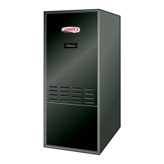
DAVE LENNOX SIGNATURE
COLLECTION OIL FURNACE
UPFLOW AIR DISCHARGE
SLO185UFV Series Units
OIL UNITS
507263-01
08/2018
Supersedes 06/2017
Table of Contents
. . . . . . . . . . . . . . . . . . . . . . . . . . . . . . . . . . . . . .
. . . . . . . . . . . . . . . . . . . . . . . . . . . . . . . . .
. . . . . . . . . . . . . . . . . . . . . . . . . . . . . . . . . .
. . . . . . . . . . . . . . . . . . . . . . . . . . . . . . . . . . . . . .
. . . . . . . . . . . . . . . . . . . . . . . . . . . . . .
. . . . . . . . . . . . . . . . . . . . . . . . . . . . . . . . . . .
. . . . . . . . . . . . . . . . . . . . . . . . . . . . . . . . . . . . .
. . . . . . . . . . . . . . . . . . . . . . . . . . . . . . . .
. . . . . . . . . . . . . . . . . . . . . . . . . . . . . . . . . . . . . .
. . . . . . . . . . . . . . . . . . . . . . . . . . . . . . . .
. . . . . . . . . . . . . . . . . . . . . . . . . . . . . . .
General
These instructions are intended as a general guide and do
not supersede local codes in any way. Only licensed pro
fessional technicians, or equivalent, can install and service
the Dave Lennox Signaturet Collection SLO185UFV oil
furnaces. In Canada, refer to CSA B139 for recommended
installation procedures. Consult authorities who have juris
diction before installation.
Never burn garbage or paper in the heating system.
Never leave papers near or around the unit.
Shipping & Packing List
1 - Assembled oil furnace
1 - Barometric draft control
1 - High fire oil nozzle (used to convert to high fire 105
and 141 inputs)
Check the components for shipping damage. If you find
any damage, immediately contact the last carrier.
Page 1
®
. . . . . . . . . . . . . . . . . . . . . . . .
. . . . . . . . . . . . . . . . . . .
. . . . . . . . . . . .
. . . . . . . . .
. . . . . . . . . . . . . . . . . . . .
. . . . . . . . . . . . . . . . . . . . . . . .
. . . . . . . . . . . . . . . . . . .
. . . . . . . . . . . . . . . . . . . . . . . . . .
. . . . . . . . . . . . .
. . . . . . . . . . . . . . . . . . . .
CAUTION
Litho U.S.A.
1
1
2
3
3
4
5
6
7
7
10
10
10
12
12
12
16
19
20
21
22
Advertisement
Table of Contents

Related Manuals for Lennox SIGNATURE SLO185UFV Series


Summary of Contents for Lennox SIGNATURE SLO185UFV Series
-
Page 1: Table Of Contents
Only licensed pro sional installer, or equivalent, or service agency. fessional technicians, or equivalent, can install and service the Dave Lennox Signaturet Collection SLO185UFV oil WARNING furnaces. In Canada, refer to CSA B139 for recommended installation procedures. -
Page 2: Slo185Ufv Unit Dimensions
SLO185UFV Unit Dimensions - Inches (mm) 3/4 (19) 3/4 (19) TOP FLUE OUTLET SUPPLY OPENING FLUE CONNECTION (On Heat TOP VIEW Exchanger) SIDE FLUE OUTLET CENTERING HOLE (Field Fabricate Either Side) ELECTRICAL INLET (Right Side Only) OIL PIPING INLET (Left Side Only) (1372) OPT. -
Page 3: Slo185Ufv Unit Parts Arrangement
SLO185UFV Unit Parts Arrangement HEAT EXCHANGER FLUE COLLAR CLEAN- CLEAN- OUT PORT OUT PORT LIMIT SWITCH OBSERVATION PORT VARIABLE SPEED BLOWER MOTOR BECKETT NX BURNER BLOWER CONTROL CAPACITOR INDOOR BLOWER Figure 2 SLO185UFV NX Burner Parts Arrangement Heat Shield Ignitor Air Tube Inlet Air Box Burner Control... -
Page 4: Requirements
2. Unit service and accessibility clearances Installation of Lennox oil-fired furnaces must conform with take precedence over fire protection clearances. the National Fire Protection Association Standard for the Table 2 Installation of Oil Burning Equipment, NFPA No. -
Page 5: Combustion & Ventilation Air
or clothes dryers are used at the same time as the furnace, Notice to Home Owner much more air is required to ensure proper combustion This furnace is equipped with safety devices that protect and to prevent a down‐draft situation. Insufficient amounts you and your property. -
Page 6: Locate & Level The Unit
When ducts are used, they shall be of the same cross-sec Equipment In Confined Space tional area as the free area of the openings to which they All Air From Inside connect. The minimum dimension of rectangular air ducts Chimney or Oil Ven shall be no less than 3”... -
Page 7: Adjustments
Level the unit from side to side and from front to rear. If the (figure 7) to remove the entire burner assembly from the furnace is not level, place fireproof wedges or shims be furnace. There is adequate wire to remove the burner with tween the low side of the furnace and the floor. -
Page 8: Venting
Indoor Coil Placement WARNING When matching a Lennox branded Acoil to an upflow oil This furnace is certified for use with type “L” vent. furnace, make sure coil width is appropriate for full air flow “B” vent must not be used with oil furnaces. - Page 9 10 - Extend the vent pipe into the chimney so that it is flush 13 - The vent pipe shall not be connected to a chimney with the inside of the chimney liner. Seal the joint be vent serving a solid fuel appliance or any mechanical tween the pipe and the liner.
-
Page 10: Flue Connections
6 - After it has been determined that each appliance re NOTE - The following are suggested procedures that should maining connected to the common venting system be followed when installing the supply air plenum. properly vents when tested as outlined above, return 1. - Page 11 Table 3 Fuel Pump Usage Pump Piping Application Maximum Lift (vacuum) One-Pipe System 8 ft. (6” Hg vacuum) Single-Stage Pump Two-Pipe System 10 ft. (12” Hg vacuum) 10 ft. or greater Two-Stage Pump Two-Pipe System (12” to 17” Hg vacuum) Oil Piping - One‐Pipe System Oil Piping - Two‐Pipe System AIR VENT...
-
Page 12: Oil Supply Line & Filter Connections
Table 6 Oil Supply Line & Filter Connections Oil Filters Cat. No. 10 micron filter (no mounting bracket) 81P89 One-Pipe Systems 10 micron filter (mounting bracket) 53P92 CAUTION 10 micron replacement cartridge for filter, 45 gph 53P93 Filter restriction indicator gauge 53P90 Do not install the bypass plug into the pump on one- pipe systems. - Page 13 IMPORTANT CAUTION Failure to use properly sized wiring and circuit If using a programmable thermostat, be sure to use breaker may result in property damage. Size wiring a type of thermostat that retains its memory in event and circuit breaker(s) per Product Specifications of a power loss.
- Page 14 Field Wiring Diagrams 1 Heat / 1 Cool 1 Heat / 2 Cool 1 Heat / 1 Cool 1 Heat / 2 Cool With Thermostat Dehumidification Mode With Thermostat Dehumidification Mode Figure 17 Page 14...
- Page 15 Field Wiring Diagrams (Continued) Dual Fuel Single-Stage Heat Pump Dual Fuel Two-Stage Heat Pump With Dual Fuel Control Mode With Dual Fuel Control Mode Dual Fuel Two-Stage Heat Pump With Dual Fuel Control Mode and Thermostat Dehumidification Mode Figure 18 Page 15...
-
Page 16: Blower Control
When the demand for cool is met, the blower ramps down Blower Control (A54) to 82% CFM for 60 seconds, then turns off. WARNING COOL (two‐stage systems) Electric shock hazard. Can cause This unit is factory-wired for single-stage cooling. For injury or death. - Page 17 CFM LED Heat Pump Applications The CFM LED located on the blower control flashes one time per 100 cfm to indicate selected blower speed. For example, if the unit is operating at 1000 CFM, the CFM LED will flash 10 times. To blower motor At times, the light may appear to flicker or glow.
- Page 18 Table 7 BLOWER DATA SLO185UF79/105V42 BLOWER PERFORMANCE 0 through 0.50 in. w.g. External Static Pressure Range Jumper Speed Positions “HEAT” Speed “ADJUST” “COOL” Speed Jumper .65 High Fire .50 Low Fire Setting 1500 1400 1200 1000 NORM 1500 1200 1400 1200 1000 –...
-
Page 19: Unit Start Up & Adjustments
Fuel Pump Pressure Adjustment Unit Start-Up & Adjustments Measure fuel pump pressure with unit off. Attach pressure Before starting unit, make sure the oil tank is adequately gauge to pump outlet. Turn unit on and check pressure and filled with clean No. 1 or No. 2 furnace oil. compare to table 9. -
Page 20: Service
10. Using a suitable thermometer, obtain and record the against the data given in the appropriate Lennox flue gas temperature at the service hole. Product Specifications bulletin. Additional informa... -
Page 21: Burner Control
7. Clean around the burner, blower deck and vestibule area. NOTE - A heat exchanger clean‐out kit ABRSH380 (35K09) is available from Lennox. The Kit includes one radiator brush (which consists of a tapered brush with a 36” spiral wire handle). -
Page 22: Troubleshooting
Table 10 Reset Button Operation Pushing the reset button will: If the burner is in the below state: Button Click Button Hold Button Hold (press < 1 second) (press > 1 second) (press 15+ seconds) Reset from Restricted o r f (Hard) Lockout Valve-on Delay, Trial for Disable the Burner:... - Page 23 Troubleshooting: Blower Control Operating Sequence Action System Response Thermostat calls for heat. ST9103A closes oil primary control TR-TW contacts. (W terminal is energized.) Ignition system and oil primary control start the furnace. Oil flows as long as cad cell senses flame. Call for heat energizes burner motor and blower ramping begins for heating mode.
- Page 24 Troubleshooting: Burner fails to start. Source Procedure Causes Correction Thermostat in OFF or COOL Switch to HEAT. Thermostat Check thermostat settings. Turn thermostat to higher tem Thermostat is set too low perature. Burner motor overload tripped Push reset button pump motor. Primary control tripped on safe...
- Page 25 Troubleshooting: Burner starts, but no flame is established. Source Procedure Causes Correction Check tank gauge or use dip No oil in tank Fill tank. stick. Coat dip stick with litmus paste If water depth exceeds 1 inch, Oil Supply Water in oil tank and insert into bottom of tank.
- Page 26 Troubleshooting: Burner starts and fires, but lock out on safety. Source Procedure Causes Correction Unbalanced fire Replace nozzle Reduce combustion air - check Too much air - -lean short fire If burner con combustion. tinues to run, Increase combustion air - check this may be Too little air - - long dirty fire Poor Fire...
- Page 27 Troubleshooting: Burner starts and fires, but short cycles (too little heat) Source Procedure Causes Correction Heat anticipator set too low Correct heat anticipator setting. Vibration at thermostat Correct source of vibration. Thermostat Check thermostat. Thermostat in the path of a Shield thermostat from draft or warm air draft relocate.
- Page 28 Troubleshooting: Burner runs continuously (too little heat). Source Procedure Causes Correction Too much combustion air Reduce combustion air. Air leaks into heat exchanger Correct cause of air leak. around inspection door, etc. Low CO less Adjust barometric draft con than 10%. Excessive overfire draft trol for correct draft.
Need help?
Do you have a question about the SIGNATURE SLO185UFV Series and is the answer not in the manual?
Questions and answers