Table of Contents
Advertisement
Quick Links
Advertisement
Table of Contents

Related Manuals for Time Electronics 5075


Summary of Contents for Time Electronics 5075
- Page 1 User Manual 5075 Digital Multimeter Version 1.1 June 2021 Time Electronics Ltd Unit 5, TON Business Park, 2-8 Morley Road, Tonbridge, Kent, TN9 1RA, United Kingdom. T: +44 (0) 1732 355993 | F: +44 (0) 1732 350198 mail@timeelectronics.co.uk | www.timeelectronics.com...
- Page 2 All rights reserved. Nothing from this manual may be multiplied, or made public in any form or manner, either electronically or hard copy, without prior written consent from Time Electronics Ltd. This also applies to any schematics, drawings and diagrams contained herein.
-
Page 3: Table Of Contents
Time Electronics User Manual 5075 Digital Multimeter v1.1 Contents Safety Guidelines........................... 5 Introduction ............................ 6 Installation ............................7 Rear Panel ............................. 7 Grounding Requirements ........................7 Power Requirements ..........................8 Setting the Line Voltage ........................8 GPIB (IEEE 488) Connection ........................ 8 Bench Use ............................. - Page 4 10.2 Connections ............................58 10.3 Operating the Scanner ........................59 10.4 Scanner Specifications ........................59 11 5075 Internal Componentry Information ..................60 11.1 Digital Board ............................60 11.2 Analogue Board ........................... 61 11.3 True RMS AC Voltage Measurements ....................62 11.4...
-
Page 5: Safety Guidelines
This manual contains information and warnings, which the operator should follow to ensure their own safety and continued operation of the instrument. The 5075 has been designed and tested in accordance with the recommendations of IEC 348 Class 1. Protection is assured by a direct connection via the power cable from ground to exposed metal parts and internal ground screens. -
Page 6: Introduction
A benchtop digital multimeter that combines high performance and accuracy with simple operation. With speed and precision, the 5075 measures from nanovolts to 10 kV, from picoamps to 30 Amps, from nano-ohms up to 1 GΩ, and from picofarads to 300 μF. It is ideal for users requiring a cost-effective DMM with multiple functions and exceptional resolution and accuracy up to 7½... -
Page 7: Installation
Time Electronics User Manual 5075 Digital Multimeter v1.1 Installation This chapter contains information about the power requirements, fuses and installation of the instrument into a 19” rack mount frame. Rear Panel Power Mains input and Scanner Inputs Current Switch voltage selector... -
Page 8: Power Requirements
Time Electronics User Manual 5075 Digital Multimeter v1.1 Power Requirements You can operate the multimeter from a single-phase source rated at 110 V AC, 220 V AC, or 240 V AC 50/60 Hz. Line voltage may vary by up to 10 % but must not exceed 250 V AC. -
Page 9: 19" Rack Mounting
Time Electronics User Manual 5075 Digital Multimeter v1.1 19” Rack Mounting Refer to Figure 3.1, removing the feet and Figure 3.2, rear fixing detail. To mount the instrument in a 19” rack you must first have the 19” rack mount kit (part # 9728). -
Page 10: Basic Operation Procedure
Dual Display Off • The 5075 will perform an internal calibration of the full scale, zero and linearity of its A/D converter every 5 minutes or when the internal temperature changes by more than one degree Celsius. This will take less than 1 second. -
Page 11: The Display
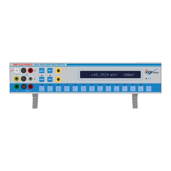
2 hrs. The Display The 5075 has a multipurpose display. Not only will it display the measured value, but it will also display its range and function. The display may also be used in a ‘dual display’ mode to simultaneously display the frequency of an ac voltage or current input. -
Page 12: Warning Messages
5075 Digital Multimeter v1.1 Warning Messages During operation, the 5075 may display messages indicating attention is required. For example, the internal temperature may be outside its specifications and will display an error message displaying this. Also, if the unit is out of its calibration period, a message will be displayed. The message... - Page 13 During a null the instrument will display: NULLING RANGE If the 5075 is in auto-range ‘Nulling Ranges’ will be displayed and all ranges will be nulled. An upper or lower case N will appear in the display to indicate a null value. An upper case N will show that there is a large offset (over 1% of full scale) and the lower case n will indicate a small offset.
- Page 14 150 ms, 250 ms, 500 ms, 1 s, 2 s, 4 s, 8 s, 16 s, 32 s and off. A unique feature of the 5075 is the Auto - Dynamic Filter which may be enabled in the menu options.
-
Page 15: Dc Voltage Measurements
In most cases the guard terminal may be connected to the V- terminal. Thermal EMF’s may also affect the readings. The terminals of the 5075 are made from Linear Crystal Oxygen Free Copper to minimise this effect. Nickel plated brass 4mm banana plugs should be avoided since they produce significant thermal EMF’s adding errors to the... - Page 16 Time Electronics User Manual 5075 Digital Multimeter v1.1 If noisy readings are encountered or when the source to be measured presents an unbalanced impedance to the measuring terminals, screened twisted pair cable should be used with the shield taken to the guard terminal and the guard input taken to the source of the common mode voltage.
- Page 17 8684. Connectors (6204) are available to make your own cables using UR43 or similar high voltage rated cable. No high voltage should be applied until full connection to the 5075 has been made. It is most important to connect the 4 mm V- terminal to ground before connecting the BNC plug.
-
Page 18: Dc Current Measurements
The same precautions may be applied for current measurement as for voltage measurement. Since the 5075 is capable of measuring very low currents, the use of screened twisted pair cable will help reduce any induced signals if necessary. At this level care should be taken, especially if the current source is mains powered. Careful earthing and guarding will reduce noise. - Page 19 Time Electronics User Manual 5075 Digital Multimeter v1.1 The table below shows the full scale, resolution and shunt resistance for each range. RANGE MAXIMUM RESOLUTION SHUNT RESISTANCE 3 uA 10 kΩ 10 uA 10 kΩ 30 uA 1 kΩ 100 uA 1 kΩ...
- Page 20 Time Electronics User Manual 5075 Digital Multimeter v1.1 4.6.1 Making a High Current Measurement Currents from 3 Amps up to 30 Amps may be measured using the separate high current terminals. If a high current has been applied for any length of time it may produce thermal EMF’s within the instrument from the current shunt.
-
Page 21: Resistance Measurements
For high value resistances most of the problems arise from 50/60 Hz line pick-up. The 5075 can be easily saturated by noise at high resistance and low source currents. Careful earthing and guarding will again help. - Page 22 Time Electronics User Manual 5075 Digital Multimeter v1.1 If the lead resistance is large in comparison to the value being measured, the readings will be inaccurate. Under these circumstances, the four terminal measurement method would give better readings however, the null function may be used to compensate for the lead resistance.
- Page 23 Time Electronics User Manual 5075 Digital Multimeter v1.1 4.7.2 Four Wire Resistance Measurements The use of four wire measurements for resistance, effectively eliminates any lead and connection resistances. Current is passed through the current leads and the voltage developed across the resistance is measured by the voltage terminals.
- Page 24 Time Electronics User Manual 5075 Digital Multimeter v1.1 4.7.3 Nulling with Four Wire Ohms If accurate measurements are to be made using four wire ohms it is recommended that the following procedure is used to null the lead resistance and any offsets before any measurements are made.
-
Page 25: Capacitance Measurements
Time Electronics User Manual 5075 Digital Multimeter v1.1 Capacitance Measurements To measure an unknown capacitor, select capacitance mode and set to auto-range. For large capacitances, ensure that they have been discharged prior to measurement. Use the connections shown below, observing polarity. Allow for lead capacitance in the test leads. -
Page 26: Using The Diode Tester
Time Electronics User Manual 5075 Digital Multimeter v1.1 Using the Diode Tester The diode test function will pass a current of 1mA through the diode under test and display the diode forward voltage. This function is particularly useful for zener diodes up to 10V. Forward voltage drops in... -
Page 27: True Rms Ac Voltage Measurements
Time Electronics User Manual 5075 Digital Multimeter v1.1 4.10 True RMS AC Voltage Measurements Measurement of AC Voltage is performed in much the same manner as DC measurements. DC voltage measurements can be made with little account taken of the lead resistance, as long as it is small in comparison to the input impedance of the DMM. - Page 28 Time Electronics User Manual 5075 Digital Multimeter v1.1 Table below shows the maximum resolution, maximum applied frequency and input impedance for each range. RANGE FREQUENCY RANGE MAXIMUM RESOLUTION INPUT IMPEDANCE 30 mV 40 Hz – 20 kHz 100 MΩ 300 mV 40 Hz –...
-
Page 29: True Rms Ac Current Measurements
When measuring low value AC currents from a mains powered source, there will be capacitive coupling from the output to earth. Whilst the 5075 input is floating respect to earth, there is still capacitive coupling to earth. This capacitive coupling may short or present a low resistance across the input. -
Page 30: Measuring Ac + Dc Voltage Or Current
Time Electronics User Manual 5075 Digital Multimeter v1.1 Table below shows the maximum frequency, resolution and shunt resistance for each range. RANGE FREQUENCY RANGE MAXIMUM RESOLUTION SHUNT RESISTANCE 30 uA 1 kHz 10 kΩ 300 uA 1 kHz 1 kΩ... -
Page 31: Frequency Measurement Using Ac Function
First select the measurement type, AC voltage or current, and then select the correct range. Connections for frequency measurement are shown below. With the 5075 displaying the correct AC voltage or current, press the 'FREQ' button to display the frequency reading. -
Page 32: Advanced Operation Procedure
Time Electronics User Manual 5075 Digital Multimeter v1.1 Advanced Operation Procedure Menu Options Options such as key beep, filter types and dual display modes can be altered via the menu. Calibration data and other information can be stored and viewed via this menu. - Page 33 Selecting this option will recalibrate the internal analogue to digital converter. This should be performed before recalibrating the instrument. Internal Temp This displays the internal temperature of the 5075 and is updated approximately every 5 minutes. The internal temperature is used to perform an internal calibration when the temperature varies by 1 C, thus insuring the temperature co-efficient of the unit remains negligible.
- Page 34 Time Electronics User Manual 5075 Digital Multimeter v1.1 Date Just as the time option, the date may be displayed or entered using this option. Press the E/User Func key to enter the date. The date must be entered in the DD/MM/YY format.
- Page 35 Sample Beep When this option is set on, the 5075 will beep when a new reading has been taken. This may be used as an indication of an updated reading for very long filter times. This is effective on filter times of 1 second and greater.
- Page 36 Time Electronics User Manual 5075 Digital Multimeter v1.1 Cal Date This will show the date of the last calibration. This may be altered if a calibration key has been plugged in. Cert No. The calibration certificate number may be displayed. This may be altered if a calibration key has been plugged in.
- Page 37 Time Electronics User Manual 5075 Digital Multimeter v1.1 Component Test The component testing function may be used for component selection. For example, if you were testing 1kΩ resistors to be within ± 1% of spec. Select the resistance function and select the 1kΩ range.
-
Page 38: Measurement Techniques
This chapter is an introduction to improving your readings using common measurement techniques and hints on how to get the best performance from your 5075 DMM. It has not been designed to be definitive or fully comprehensive but to be used as a guide only. -
Page 39: Using The Guard On Resistance
Time Electronics User Manual 5075 Digital Multimeter v1.1 Using the Guard on Resistance The Guard is equally effective on resistance as it is for voltage and current measurements and may be used in both two wire and four wire mode. -
Page 40: Input Impedance And Lead Capacitance
Time Electronics User Manual 5075 Digital Multimeter v1.1 Input Impedance and Lead Capacitance Input impedance is the equivalent resistance and capacitance as if you were looking into the DMM’s input terminals. With most DC measurements up to 10 V, input impedance of the DMM and the lead resistance is unimportant as long as the resistance of the circuit measured is small in comparison to the input impedance of the meter. - Page 41 Time Electronics User Manual 5075 Digital Multimeter v1.1 By minimising the temperature gradients within a circuit, thermal emfs are reduced. One method would be to place all junctions in close proximity and provide a good thermal connection to all of them. The thermal conductor must be chosen carefully as most electrical insulators do not conduct heat very well.
-
Page 42: Making High Value Resistance Measurements
Making High Value Resistance Measurements Low value, constant current measurement techniques must often be used to determine the value of a high resistance. This is also the method used in the 5075. This diagram shows the basis of constant current resistance measurement. -
Page 43: Dc Current Measurement Errors
When measuring current, a small voltage drop will appear across the meter due to the current shunt and protection devices. This voltage drop is called the ‘Burden Voltage’. With the 5075, the Burden Voltage has been kept to a minimum, generally up to a maximum of 100mV. -
Page 44: True Rms
DMM would display 11.1 V, an error of 11 %. Bandwidth Be aware that the accuracy of the 5075 is specified up to 20 kHz or 1 kHz and 60 Hz on the higher ranges. Particular limitations are applied because of the circuit configuration. Any signal outside of this range will not be an accurate measurement. -
Page 45: Zero Ac Input Error
This is due to random noise and the non-linear characteristics of the RMS converter to small inputs. This however should not be a problem as the 5075 has seven AC voltage ranges with long scale resolution. Also, the non-linearity error is dramatically reduced when an input is applied. -
Page 46: Ieee (Gpib) Operation
Repetitive calibration work can be speedily and accurately carried out, giving printed results if required. The 5075 is compatible with the IEEE - 488 (1978) interface bus. The IEEE - 488 standard defines a complete interface system for the interconnection of instruments and computers using a bit parallel, byte serial bi-directional bus. -
Page 47: Ieee Connector
Time Electronics User Manual 5075 Digital Multimeter v1.1 IEEE Connector The pin connections and dimensions of the IEEE connector are illustrated in Figure 7.1 and in Table 7.1. Figure 7.2 illustrates the connections. IEEE – 488 IEC - 625 STANDARD... -
Page 48: Ieee Address Selection
Local/Remote Operation The 5075 is switched into remote operation when a valid command is received on the IEEE bus. The unit will remain in remote control until the MENU/LOCAL key is pressed on the DMM or until the unit is switched off. -
Page 49: Ieee Command Format
QuickBasic language by Microsoft command. Refer to your IEEE controller for specific commands. The 5075 command string consists of commands from the 5075 Instruction set. These commands will instruct the 5075 to perform measurement functions or other operations. -
Page 50: Ieee Command List
Time Electronics User Manual 5075 Digital Multimeter v1.1 7.11 IEEE Command List RANGE DC VOLTAGE AC VOLTAGE DC CURRENT AC CURRENT OHMS CAPACITANCE FREQUENCY AUTORANGE OFF AUTORANGE ON 3 mV 3 mV 3 uA 3 uA 30 mΩ 30 nF... -
Page 51: Transmitted Value Format
Time Electronics User Manual 5075 Digital Multimeter v1.1 SCANNER CHANNEL MENU FUNCTIONS SERIAL No. CERTIFICATE No. CALIBRATION DATE CALIBRATION DUE DATE CALIBRATION TEMPERATURE CALIBRATION PERIOD DATE TIME INTERNAL TEMPERATURE IEEE ADDRESS OHMS COMPENSATION MODE COMPENSATION OFF COMPENSATION ON 7.12 Transmitted Value Format When the ‘D’... -
Page 52: Programming Example
Time Electronics User Manual 5075 Digital Multimeter v1.1 7.13 Programming Example The following simple demonstration program written in Basic takes one reading from the DMM. The IEEE interface card in your computer may be different from the one used in this example program. -
Page 53: Re-Calibration
Calibration periods may be chosen by the customer depending upon the accuracy required from the instrument. The 5075 may be calibrated at any time and any individual range may be calibrated. The 5075 will require recalibration when the below message appears on the display: CALIBRATION OUT OF DATE You may calibrate a range to a specific input value or to its full scale value. -
Page 54: Front Panel Re-Calibration
Also in the menu options, the calibration details should be updated, i.e. Cal Period, Cal Due, Cal Date, Cert Number. To avoid calibration errors, the 5075 will only alter its calibration factors in small steps. Therefore, large changes in value will require more than one attempt. -
Page 55: Specifications
Time Electronics User Manual 5075 Digital Multimeter v1.1 Specifications Technical/General Specifications For technical and general specifications, please see the 5075 Extended Specifications document that accompanies this user manual. It can also be downloaded at www.timeelectronics.com. Operating Information/Features 9.2.1 N Digits This changes the reading resolution, which can be changed from 4 up to 7 digits (depending on the scale selected). - Page 56 Time Electronics User Manual 5075 Digital Multimeter v1.1 9.2.7 Diode / Zener Diode Test The diode test function will passes a current of 1 mA through the diode under test and displays the diode forward voltage. May be used for zener diodes up to 10 V.
- Page 57 The Date and Time can be displayed or entered using this option. 9.2.18 Internal Temp The internal temperature of the 5075 can be displayed and is updated approximately every 5 minutes. The internal temperature is used to perform an internal calibration when the temperature varies by 1 C, thus ensuring the temperature co-efficient of the unit remains negligible.
-
Page 58: Scanner Option 9726
10.1 Fitting the Scanner (Option 9726) The scanner option for the 5075 DMM consists of an internally fitted relay board. This board contains 10 low thermal emf, multiple plated moving armature relays and its driver circuitry. Up to two boards may be fitted giving up to 20 channels. -
Page 59: Operating The Scanner
Time Electronics User Manual 5075 Digital Multimeter v1.1 10.3 Operating the Scanner The relays switch all 4 input terminals: V+, V-, I+, I– to one of 10/20 inputs via the 25 way ‘D’ connectors. It is important to observe the maximum ratings of the scanner option, which are detailed in the specifications section. -
Page 60: 5075 Internal Componentry Information
5075 Digital Multimeter v1.1 5075 Internal Componentry Information This chapter is a brief introduction to the technical details of the 5075 internal parts. The 5075 consists of two main boards with plug in modules. 1) The PSU and Processor board. -
Page 61: Analogue Board
Time Electronics User Manual 5075 Digital Multimeter v1.1 The LED’s on the front panel are driven by two 8 bit data latches, I.C. 21 and I.C. 22, both 74LS273. An additional PIA is used to drive the parallel printer port and also to provide the processor with information of installed options. -
Page 62: True Rms Ac Voltage Measurements
Time Electronics User Manual 5075 Digital Multimeter v1.1 11.2.3 Resistance Measurements Resistance is measured by passing a known current through the unknown resistance being measured. The voltage developed across this is then measured by the DC voltage circuit. Ohms law is then used to give the resistance. -
Page 63: Fault Diagnosis
The unit displays ‘Cal Factor Error’. The unit has a corrupted calibration factor and will need recalibrating. The 5075 occasionally resets to power on state. Excessive mains interference is causing the uP to stop. The watchdog circuit is causing the reset. Add additional mains filtering. -
Page 64: Fuse Replacement
12.2 Fuse Replacement The 5075 has three types of fuse fitted. The mains fuse must be of the 20 mm, HBC, Sand filled and ceramic body type. The internal DC supplies have two 1A, 20 mm anti-surge for the +15V and –15V rails and two 2A, 20 mm semi-delay (type T) fuses for the 5V and 5/12V rail. - Page 65 12.2.4 Replacing the Capacitance Range Fuse The capacitance range fuse may be found on the rear panel of the 5075, in between the current fuse holders and the rear input terminals. The fuse rating is 50 mA, Quick blow, 15 mm glass.
-
Page 66: Replacement Of Analog Or Digital Boards
Time Electronics User Manual 5075 Digital Multimeter v1.1 12.3 Replacement of Analog or Digital Boards Only qualified personnel should attempt replacement of the analogue or digital circuit boards. Recalibration will be required if the analogue board has been replaced or if the calibration RAM (I.C. -
Page 67: Replacing The Clock Backup Battery
12.4 Replacing the Clock Backup Battery The replacement battery must be as specified by Time Electronics. (Time Electronics part number 7638.) Replacing the real time clock backup battery is best done with the digital board removed from the case as described in the previous section. Also read the important safety notes about Lithium batteries. -
Page 68: Spare Parts List
Time Electronics User Manual 5075 Digital Multimeter v1.1 Spare Parts List 5075 spare parts listed below. Contact Time Electronics for availability and pricing. Main Parts 2593 ....Rear Panel Label 7511 ....Mains Transformer 2594 ....Front Panel Label 9039 ....Front Feet 2750 .... -
Page 69: Warranty And Servicing
Time Electronics’ total liability is limited to repair or replacement of the product. Note that if Time Electronics determine that the fault on a returned product has been caused by the user, we will contact the customer before proceeding with any repair. - Page 70 Returning Instruments Prior to returning your product please contact Time Electronics. We will issue a return merchandise authorization (RMA) number that is to accompany the goods returning. Further instructions will also be issued prior to shipment. When returning instruments, please ensure that they have been adequately packed, preferably in the original packing supplied.
Need help?
Do you have a question about the 5075 and is the answer not in the manual?
Questions and answers