
Subscribe to Our Youtube Channel
Related Manuals for Body Solid Endurance T100A


Summary of Contents for Body Solid Endurance T100A
- Page 1 T100A Z100 / Z300 Z500 Z700 T100 OWNER’S MANUAL PLEASE CAREFULLY READ THIS ENTIRE MANUAL BEFORE v. 091709 Endurance OPERATING YOUR NEW TREADMILL! T100A Treadmill ® User Manual v. T100A-030513...
-
Page 2: Table Of Contents
Table of Contents RefeRence DRawIngs......BefoRe You BegIn........III. IMPoRTanT safeTY InsTRucTIons..safeTY guIDelInes........6 - 9 asseMBlY InsTRucTIons......10 - 11 asseMBlY sTePs........12 - 17 VII. seTTIng uP YouR TReaDMIll....VIII. oPeRaTIng YouR TReaDMIll....oPeRaTIng THe console......20 - 22 PRogRaM feaTuRes........ -
Page 3: Reference Drawings
Reference Drawings note: Due to continuing product improvements, specifications and designs are subject to change without notice. Even though we have prepared this manual with extreme care, neither the publisher nor the author can accept responsibility for any errors in, or omission from, the information given. -
Page 4: Before You Begin
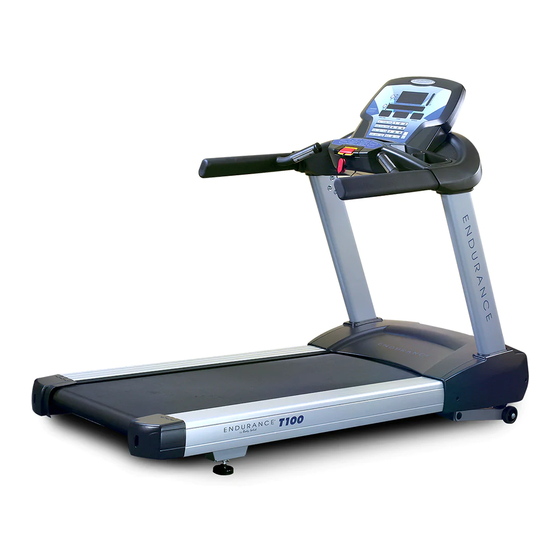
Before you Begin Thank you for purchasing the Endurance T100 Treadmill. To maximize your use of the equipment please study this Owner’s Manual thoroughly. Unpacking the eqUipment The T100 is carefully tested and inspected before shipment. We have shipped the unit in several pieces that require assembly. -
Page 5: Important Safety Instructions
Important Safety Instructions Before beginning any fitness program, you should obtain a complete physical examination from your physician. Il est conseille de subir un examen medical complet avant d’entreprendre tout programme d’exercise. Si vous avez des etourdissements ou des faiblesses, arretez les exercices immediatement. When using exercise equipment, you should always take basic precautions, including the following: Read all instructions before using the T100. -
Page 6: Safety Guidelines
Safety Guidelines Successful cardio training programs have one prominent feature in common...safety. Cardio training has some inherent dangers, as do all physical activities. The chance of injury can be greatly reduced or completely removed by using correct running techniques, proper breathing, maintaining equipment in good working condition, and by wearing the appropriate clothing. - Page 7 Important Electrical Information Safety Guidelines WARNING! NEVER use a RCD - Residual Current Device (U.S. ver.= GFCI) - wall outlet with this treadmill. As with any appliance with a large motor, the RCD/GFCI will trip often. Route the power mains cord away from any moving part of the treadmill including the elevation mechanism and eleCtriCal safety transport wheels.
- Page 8 Safety Guidelines This exercise equipment is designed and built for optimum safety for home use. However, certain precautions always apply whenever you operate any exercise equipment. Be sure to read the entire manual before assembly and operation of this machine. Also, please note the following safety precautions.
- Page 9 Safety Guidelines impORtant OpeRatiOn inStRUctiOnS ● NEVER operate this treadmill without reading and completely understanding the results of any operational change you request from the computer. ● Understand that changes in speed and incline do not occur immediately. Set your desired speed on the computer console and release the adjustment key.
-
Page 10: Assembly Instructions
Assembly Instructions professional installers are highly recommended! However, if you acquire the appropriate tools, obtain assistance, and follow the assembly steps sequentially, the process will take time, but is fairly easy. aSSembLY tipS Read all “NoteS” on each page before beginning each step. While you may be able to assemble the T100 using the illustrations only, important safety notes and other tips are included in the text. - Page 11 Hardware Pack Check List Assembly Pack Check List Step1 #117 - 3/8" x16.5 x2.0T x4H #116 -ψ3/8" x 35 x 2T Split Washer (6 pcs) Flat Washer (6 pcs) #144 - 3/8”-16 x 3” #134 - M5 x 12mm Button Head Socket Bolt (6 pcs) Phillips Head Screw (4 pcs) Step2 #134 - M5 x 12mm...
- Page 12 Step 1 Be careful to assemble all components in the sequence they are presented. Attach Right Upright (#34) to Frame Base using: one retaining Plate (#98) three 3/8”-16 x 3” button Head socket bolts (#144) three 3/8” lock Washers (#117) three 3/8”...
- Page 13 Step 1 Above shows STEP 1 assembled and completed.
- Page 14 Step 2 Be careful to assemble all components in the sequence they are presented. Connect Upper Computer Cable B (#41), Hand Pulse Assembly C & D (#37 & #38), Touch Pad/Backlit Cable E(#43) and Groud Wire F (#35) to the board on on back of the console (#28) Attach Console Assembly (#28) to Console Support (#5) using: Four M5x12mm Phillips Head Screws (#134)
- Page 15 Step 2 Above shows STEP 2 assembled and completed.
- Page 16 Step 3 Be careful to assemble all components in the sequence they are presented. Attached the console to Mounting Brackets (#3 & #4) using: Six M8x12mm Socket Head Cap Screws (#146) Connect Upper Computer Cable F (#41) to Lower Computer Cable A (#42) Attach the Mounting Brackets (#3 &...
- Page 17 Step 3 Above shows STEP 3 assembled and completed.
-
Page 18: Setting Up Your Treadmill
Setting up your Treadmill pLacement in YOUR hOme To make exercise a desirable daily activity for you, the treadmill should be placed in a comfortable and attractive setting. This treadmill is designed to use minimal floor space and to fit nicely in your home. Do not place or operate the treadmill outdoors. -
Page 19: Operating Your Treadmill
Operating your Treadmill tURn pOWeR On The On/Off switch for the treadmill is located next to the power supply cord receptacle on the front of the treadmill. Insert the power supply cord into the receptacle and flip the switch to the “ON”... - Page 20 Operation of Your Treadmill Operation of Your Treadmill getting familiar with the control panel Getting familiar with the control panel ■ Console Console Getting Started: getting Started: Power the treadmill on by plugging it into an appropriate wall outlet, then turn on the power switch located at the front of the treadmill below the motor hood.
-
Page 21: Operating The Console
Operating the Console quick-Start Operation: • Press and release the StaRt key to begin belt movement at 0.5 mph/0.8 kph, then adjust to the desired speed using the FaSt keys. • To slow tread-belt using the SLOW key to the desired speed. To stop the tread-belt press and release StOp key. - Page 22 Operating the Console Next to the Dot Matrix window are three LED lights labeled: Track, Speed and Incline, along with a DiSpLaY button. When the Track LED is lit the dot matrix displays the Track profile, when the Speed LED is lit the Dot matrix displays the Speed profile and when the Incline LED is lit the Dot Matrix displays the Incline profile.
-
Page 23: Program Features
Program Features The New TREADMILL offers twelve preset programs, HILL, FAT BURN, CARDIO, CALO- RIE, INTERVAL, STRENGTH, 5K RUN, 10K RUN, HR 1, HR 2, CUSTOM, a Gerkin protocol based Fitness Test and one Manual program. preset Features: to choose and start preset program: •... - Page 24 Program Features • There will be a 3 minute warm-up to begin. You can press the START button to bypass this and go straight to the workout. During the warm-up the clock will count down from 3 minutes. ( 5K RUN, 10K RUN, HR 1, HR 2, CUSTOM and the manual program don’t have a warm-up mode.) preset programs speed and incline settings The preset program speed and incline levels are shown in the chart below.
- Page 25 Program Features Message window is showing ”ADJUST BODY WEIGHT THEN PRESS enteR” now • with INCLINE window is blinking. After the weight is set, press “enteR” button to continue. • Message window is showing ”ADJUST TARGET CALORIES BURN THEN PRESS ENTER”...
- Page 26 Program Features • Now the message window is showing ”ADJUST INCLINE THEN PRESS ENTER”. The first column will be blinking again and INCLINE window is blinking too. The console is now ready for the incline settings. To set the incline value you want, Use Up/DOWn/FaSt/ SLOW keysto adjust the incline to your desired effort level for the first segment then press “enteR”.Repeat the same process used to set the speed values for programming the segments for incline.
- Page 27 Program Features 5 Km and 10Km Run: This program automatically sets a 5K or 10K (5 or 10 kilometer) distance as your goal. T display will show one loop that is the equivalent of 5 or 10 kilometers and the Distance w also show 5K or 10K to start.
- Page 28 Program Features before the test: • Make sure you are in good health; check with your physician before performing any exercise if you are over the age of 35 or persons with pre-existing health conditions. • Make sure you have warmed up and stretched before taking the test. •...
- Page 29 Program Features What your score means: VO2max for male and fitted female 18-25 26-35 36-45 46-55 56-65 years years years years years years excellent >60 >56 >51 >45 >41 >37 good 52-60 49-56 43-51 39-45 36-41 33-37 above average 47-51 43-48 39-42 35-38...
-
Page 30: Target Heart Rate
Target Heart Rate To obtain the greatest cardiovascular benefits from your exercise workout, it is important to work within your target heart rate zone. The American Heart Association (AHA) defines this target as 60% -75% percent of the Maximum Heart Rate. The Maximum Heart Rate may be roughly calculated by subtracting the user’s age from 220. - Page 31 Target Heart Rate Fitness saFety The Heart Rate chart indicates average rate zones for different ages. A variety of different factors (including medication, emotional state, temperature and other conditions) can affect the target heart rate zone that is best for you. Your physician or health care professional can help you determine the exercise intensity that is appropriate for your age and condition.
-
Page 32: Chest Strap Operation
Chest Strap Operation (Optional) Your Endurance ® T100 Treadmill has the capability to determine Heart Rate with the use of a Heart Rate Chest Strap. It is available as an optional accessory for use with your unit depending on the Endurance ® model purchased. In all Heart Rate Control programs, the console only accepts the heart rate signal from the chest strap transmitter while the pulse grip heart rate function is disabled. -
Page 33: Heart Rate Control Operation
Heart Rate Control Operation how the heart Rate control program Works: Heart Rate Control (HRC) uses your treadmill’s incline system to adjust your heart rate. In- creases and decreases in elevation affect heart rate much more efficiently than changes in speed alone. - Page 34 General Maintenace General Maintenance belt and bed - Your treadmill uses a very high-efficient low-friction bed. Performance is maximized when the bed is kept as clean as possible. Use a soft, damp cloth or paper Belt and Bed - Your treadmill uses a very high-efficient low-friction bed. Performance is towel to wipe the edge of the belt and the area between the belt edge and frame.
-
Page 35: General Maintenance
General Maintenance tReaDbeLt tRacking aDJUStment: The performance of your treadmill is dependent on the frame running on a reasonably level surface. If the frame is not level, the front and back roller cannot run parallel, and constant belt adjustment may be necessary. The treadmill is designed to keep the tread-belt reasonably centered while in use. -
Page 36: Troubleshooting Guide
Service Checklist - Diagnosis Guide Troubleshooting Guide Before contacting your dealer for aid, please review the following information. It may save you both time and expense. This list includes common problems that may not be covered under the treadmill’s warranty. PROBLEM SOLUTION/CAUSE Display does not light... -
Page 37: Setting/Service Guide
Setting/Service Guide calibration procedure: Remove the safety key Press and hold down the incLine and SpeeD buttons with one hand and replace the safety key with the other. Continue to hold both keys until the window displays “FactORY Setting”, then press the enteR key. You will now be able to set the display to show English or Metric settings. - Page 38 Setting/Service Guide maintenance menu: 1) Remove the safety key and press SpeeD and enteR keys at the same time then re- turn the safety key until “ENGINEERING MODE” is displayed, press enteR again. 2) You can now scroll through the menu using the Up /DOWn or FaSt/SLOW keys. Use the enteR key to run.
-
Page 39: Parts List
Parts List Description Main Frame Incline Bracket Interface Mounting Bracket, Left Interface Mounting Bracket, Right Console Support Deck Cross Brace A Deck Cross Brace B Belt Guide Right Belt Guide Left Front Roller Assembly W/Pulley Rear Roller Assembly Running Deck Running Belt Cushion A Cushion B... - Page 40 Parts List Description Right Upright Ground Wire Touch-Pad-Button Board 900m/m_Handpulse W/Cable Assembly A 900m/m_Handpulse W/Cable Assembly B Handpulse Wire (Upper) Handpulse Wire (Lower) 700m/m_Computer Cable (Upper) 1700m/m_Computer Cable (Lower) 700m/m_Pad/Backlit Cable Toggle switch Key Board AC Motor Inverter Incline Interface Board Filter Choke Motor Compartment Fan...
- Page 41 Parts List Description Incline Carriage Spacer Ø10 × Ø25 × 0.8T_Nylon Washer Sensor Rack Motor Cover Anchor 300m/m_Motor Ground Wire 450m/m_Connecting Wire(White) Retaining Plate Power Line Cord 5 × 20m/m_Tapping Screw Ø18 × Ø19 × 41L_Carriage Bolt M8 × 1.25 × 12L_Hex Head Bolt 3/8"-16 ×...
- Page 42 Parts List Description Ø3/8" × 25 × 2T_Flat Washer M10 × 1.5 × 40L_Socket Head Cap Bolt M10 × 1.5 × 80L_Socket Head Cap Bolt M10 × 1.5 × 100L_Socket Head Cap Bolt M8 × 1.25 × 55L_Flat Head Countersink Bolt M8 ×...
-
Page 43: Exploded View Diagram
Exploded View Diagram... - Page 44 Serial Number is Located on the Frame T100A Model Name Purchase Date : _______________________________ Serial Number : 008410-_______________________ Customer Tech Support Hotline Toll Free: 1-800-556-3113 Phone: 1-708-427-3555 Fax: 1-708-427-3556 Hours: M-F 8:30-5:00 CST E-Mail: service@bodysolid.com Copyright 2009. Body-Solid. All rights reserved. Body-Solid reserves the right to change design and specifications when we feel it will improve the product. Body-Solid machines maintain several patented and patent pending features and designs.
Need help?
Do you have a question about the Endurance T100A and is the answer not in the manual?
Questions and answers