Table of Contents
Advertisement
Advertisement
Table of Contents

Related Manuals for Body Solid Endurance T25


Summary of Contents for Body Solid Endurance T25
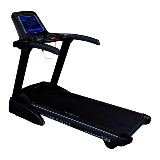
- Page 1 v. 091709 Endurance T25 Treadmill ® User Manual v. T25-20200720...
-
Page 2: Table Of Contents
Table of Contents IMPORTANT SAFETY INSTRUCTIONS......SAFETY gUIdElINES............ASSEMblY INSTRUCTIONS........... HARdWARE PACK CHECK lIST........ASSEMblY PART lIST............10 - 11 ASSEMblY STEPS............12 - 25 SETTINg UP YOUR TREAdMIll........26 - 29 OPERATINg THE CONSOlE..........30 - 33 PROgRAM FEATURES............34 - 37 gENERAl MAINTENANCE.......... -
Page 3: Important Safety Instructions
The T25 is designed for your enjoyment. by following these precautions and using common sense, you will have many safe and pleasurable hours of healthful exercise with your Endurance T25. After assembly, you should check all functions to ensure correct operation. If you experience problems, first recheck the assembly instructions to locate any possible errors made during assembly. -
Page 4: Safety Guidelines
Safety Guidelines Successful cardio training programs have one prominent feature in common...safety. Cardio training has some inherent dangers, as do all physical activities. The chance of injury can be greatly reduced or completely removed by using correct running techniques, proper breathing, maintaining equipment in good working condition, and by wearing the appropriate clothing. - Page 5 Important Electrical Information Safety Guidelines WARNING! NEVER use a RCD - Residual Current Device (U.S. ver.= GFCI) - wall outlet with this treadmill. As with any appliance with a large motor, the RCD/GFCI will trip often. Route the power mains cord away from any moving part of the treadmill including the elevation mechanism and eleCtriCal safety WARNINg!
- Page 6 Safety Guidelines This exercise equipment is designed and built for optimum safety for home use. However, certain precautions always apply whenever you operate any exercise equipment. be sure to read the entire manual before assembly and operation of this machine. Also, please note the following safety precautions.
- Page 7 Safety Guidelines IMPORTANT OPERATION INSTRUCTIONS ● NEVER operate this treadmill without reading and completely understanding the results of any operational change you request from the computer. ● Understand that changes in speed and incline do not occur immediately. Set your desired speed on the computer console and release the adjustment key.
-
Page 8: Assembly Instructions
Assembly Instructions Professional installers are highly recommended! However, if you acquire the appropriate tools, obtain assistance, and follow the assembly steps sequentially, the process will take time, but is fairly easy. ASSEMBLY TIPS Read all “NoteS” on each page before beginning each step. While you may be able to assemble the T25 using the illustrations only, important safety notes and other tips are included in the text. -
Page 9: Hardware Pack Check List
Hardware Pack Check List M8x80mm Button Head Cap Screw, 8pcs M8x15mm Button Head Cap Screw, 8pcs ST4.2x15mm Phillips Screw, 10pcs M8x30mm Socket Head Cap Screw, 4pcs M8 Washer, 16pcs... -
Page 10: Assembly Part List
Parts List 1. Main Frame, 1 pcs. 5. Upper Console, 1 pcs. 2. left Upright, 1 pcs. 3. Right Upright, 1 pcs. - Page 11 Parts List 4. lower Console, 1 pcs. 17. Safety Key, 1 pcs. 18. Power Cord, 1 pcs. 6. left Upright Cover, 1 pcs. 7. Right Upright Cover, 1 pcs. 9. left Outer Cover, 1 pcs. 8. left Inner Cover, 1 pcs. 11.
-
Page 12: Assembly Steps
Step 1 Be careful to assemble all components in the sequence they are presented. Note: Finger tighten all hardware in this step. DO NOT wrench tighten unless instructed. Look for Stickers to identify Left and Right Uprights. Attach left Upright (#2) to Main Frame (#1) using 4 - (#12) m8x50mm button Head Cap screw 1 - (#13) m8x15mm button Head Cap screw 5 - (#16) m8 Washer... - Page 13 Step 1 Above shows STEP 1 assembled and completed.
- Page 14 Step 2 Be careful to assemble all components in the sequence they are presented. Note: Finger tighten all hardware in this step. DO NOT wrench tighten unless instructed Insert left Upright Cover (#6) onto left Upright (#2). Insert Right Upright Cover (#7) onto Right Upright (#3).
- Page 15 Step 2 Above shows STEP 2 assembled and completed.
- Page 16 Step 3 Be careful to assemble all components in the sequence they are presented. Note: Wrench tighten all hardware at the end of Step 3B Connect Cable b from the Right Upright (#3) to Cable b from the lower Console (#4). Note: Be careful not to damage the cables.
- Page 17 Step 3 Above shows STEP 3 assembled and completed.
- Page 18 Step 4 Be careful to assemble all components in the sequence they are presented. Note: Wrench tighten all hardware at the end of Step 4B Connect Cables C from the lower Console (#4) to Cables C from the Upper Console (#5). Note: Be careful not to damage the cables.
- Page 19 Step 4 Above shows STEP 4 assembled and completed.
- Page 20 Step 5 Be careful to assemble all components in the sequence they are presented. Note: Please make sure the Deck of the Main Frame is fully folded up and locked. See Folding Instruction on Page 27. Attach left Inner Cover (#8) to Main Frame (#1) using 1 - (#14) st4.2x15mm Phillips screws Attach Right Inner Cover (#10) to Main Frame (#1) using 1 - (#14) st4.2x15mm Phillips screws...
- Page 21 Step 5 Above shows STEP 5 assembled and completed.
- Page 22 Step 6 Be careful to assemble all components in the sequence they are presented. Attach left Outer Cover (#9) and left Inner Cover (#8) together using: 2 - (#14) st4.2x15mm Phillips screws Attach Right Outer Cover (#11) and left Inner Cover (#10) together using: 2 - (#14) st4.2x15mm Phillips screws Note: Please make sure the Deck of the Main Frame is fully folded up and locked.
- Page 23 Step 6 Above shows STEP 6 assembled and completed.
- Page 24 Step 7 Be careful to assemble all components in the sequence they are presented. Connect Power Cord (#18) to the Main Frame (#1). Insert Safety Key (#17) onto the lower Console (#4).
- Page 25 Step 7 Above shows STEP 7 assembled and completed.
-
Page 26: Setting Up Your Treadmill
Setting up your Treadmill FOLDING THE TREADMILL 1. lift the deck of the treadmill up as shown in the drawing until you head the gas spring gives a snap sound. 2. Make sure the deck is in upright and locked position. - Page 27 Setting up your Treadmill 2. Pull back on the handrail until the treadmill will roll age latch (B) locks on the wheels, and carefully move it to the desired UNFOLDING THE TREADMILL N: Make sure that 1. Hold the rear end of the running deck with both hands. location.
- Page 28 Setting up your Treadmill PLACEMENT IN YOUR HOME To make exercise a desirable daily activity for you, the treadmill should be placed in a comfortable and attractive setting. This treadmill is designed to use minimal floor space and to fit nicely in your home. do not place or operate the treadmill outdoors.
- Page 29 Setting up your Treadmill MOVING THE TREADMILL This treadmill is easy to move around safely. To move the treadmill: 1. Turn the power switch off. 2. Unplug the power cord. 3. lift the deck of the treadmill up as shown in the drawing until you head the gas spring gives a snap sound.
-
Page 30: Operating The Console
Operating the Console CONSOLE LAYOUT OVERVIEW... - Page 31 Operating the Console DISPLAY OVERVIEW TIME: displays duration of the workout in minutes and seconds. PULSE: displays Heart Rate in beats per minute. DISTANCE: displays traveled distance during workout in miles/kilometers COLORIES: displays Calories burned during workout. SPEED: displays current speed during workout in mph INCLINE: displays current incline of your workout.
- Page 32 Operating the Console BUTTON OVERVIEW START/PAUSE : To start or pause workout. STOP : To stop workout and back to the Standby Mode. INCREASE SPEED : To increase workout speed . DECREASE SPEED : To decrease workout speed. INCREASE INCLINE : To increase workout incline level.
- Page 33 Operating the Console PROGRAM : To select different programs (Manual, Time Countdown, Distance Countdown, Calories Countdown, P01-P08, HP1-HP3). MARATHON TRAINING : To select Marathon training. distance is 26.3 miles WARM UP : To start a 3 minutes warm up. The speed is 1.0 MPH initially. The speed will increase gradually to 3.7 MPH.
-
Page 34: Program Features
Program Features PROGRAMS METRIC & STANDARD UNIT: The initial factory setting is in “Miles”. To switch between Miles & Kilometers, press QUICK SPEEd 2, 4, 6 at the same time. QUICK START: 1. In Standby mode, press the START button to enter QUICK START mode. 2. - Page 35 Program Features DISTANCE COUNTDOWN: 1. In Standby mode, press the PROgRAM button to choose dISTANCE COUNTdOWN mode. 2. Press INClINE ANd SPEEd buttons to change the dISTANCE setting. 3. Press START button to start the workout 4. during workout, SPEEd and INClINE can be changed using INClINE & SPEEd buttons.
- Page 36 Program Features HP01 - HP03 (HEART RATE SPEED CONTROL): 1. In Standby mode, press the PROgRAM button to choose HP01 - HP03 mode. 2. Press and hold PROgRAM button to enter AgE. AgE can be changed using INClINE & SPEEd buttons. 3.
- Page 37 Program Features...
- Page 38 General Maintenace General Maintenance Belt and Bed - Your treadmill uses a very high-efficient low-friction bed. Performance is Belt and Bed - Your treadmill uses a very high-efficient low-friction bed. Performance is maximized when the bed is kept as clean as possible. Use a soft, damp cloth or paper maximized when the bed is kept as clean as possible.
-
Page 39: General Maintenance
General Maintenance 调向左边 图 B 跑带调向右边 RUNNING BELT TRACKING ADJUSTMENT: The performance of your treadmill is dependent on the frame running on a reasonably level surface. If the frame is not level, the front and back roller cannot run parallel, and constant belt adjustment may be necessary. - Page 40 General Maintenance Belt Lubrication Procedure 1) Turn off the Power. 2) lift the running belt and check if there is any lubricant on the back of the running belt. If running belt needs to be lubricated, take a wiper to clean the running deck and rollers.
-
Page 41: Troubleshooting Guide
Troubleshooting Guide Problem/ Fault Possible Reason Corrective action Code 1.Not plugged in 1.Plug cord into outlet 2.Safety key not inserted 2.Insert safety key Treadmill will not 3.Switch on OFF 3.Turn switch to ON start 4.treadmill circuit breaker tripped 4.Lubricate treadmill belt and rest Running belt slips Running belt not tight enough Adjust running belt tension... -
Page 42: Parts List
Parts List DESCRIPTION MAIN FRAME ElEVATION FRAME FRONT bASE FRAME lEFT UPRIgHT RIgHT UPRIgHT lOWER CONSOlE FRAME UPPER CONSOlE FRAME lEFT bRACKET RIgHT bRACKET SPACER RUNNINg dECK RUNNINg bElT AC MOTOR INClINE MOTOR FRONT ROllER REAR ROllER POWER SWITCH OVERlOAd PROTECTOR POWER SOCKET POWER CORd MOTOR dRIVE bElT... - Page 43 Parts List DESCRIPTION lEFT INNER COVER RIgHT OUTER COVER RIgHT INNER COVER TAblET HOldER CONSOlE SUPPORT COVER FRONT CONSOlE COVER REAR CONSOlE COVER dISPlAY CONSOlE TOP COVER CONSOlE bOTTOM COVER KEY bOARd COVER lEFT UPRIgHT COVER RIgHT UPRIgHT COVER lEFT HANdRAIl COVER RIgHT HANdRAIl COVER SPRINg PlASTIC WASHER...
- Page 44 Parts List DESCRIPTION SPEAKER dISPlAY bOARd KEY bOARd INVERTER HANd PUlSE PlATE HEX HEAd bOlT, M10x45mm HEX HEAd bOlT, M10x60mm bUTTON HEAd CAP SCREW, M8x40mm bUTTON HEAd CAP SCREW, M8x50mm CARRIAgE bOlT, M8x20mm HEX HEAd bOlT, M8x70mm HEX HEAd bOlT, M8x60mm PAN HEAd PHIllIPS SCREW, M4x10mm PAN HEAd PHIllIPS SCREW, M4x15mm SOCKET HEAd CAP SCREW, M8x75mm...
- Page 45 Parts List DESCRIPTION CAblE, 800mm gROUNd CAblE, 600mm MAgNETIC RINg, Ø24.75xØ15.2x14.9mm MAgNETIC RINg, Ø39xØ13x31mm MAgNET, Ø20xØ8.5x36mm MAgNET, b5H lOWER CONSOlE ASSEMblY UPPER CONSOlE ASSEMblY...
-
Page 46: Exploded Drawing
Exploded Drawing... - Page 47 Exploded Drawing EXPlOdEd dRAWINg OF UPPER CONSOlE ASSEMblY EXPlOdEd dRAWINg OF lOWER CONSOlE ASSEMblY...
- Page 48 Serial Number is Located on the Upright Model Name : _______________________________ Purchase Date : _______________________________ Serial Number : 016057-_______________________ Customer Tech Support Hotline Toll Free: 1-800-556-3113 Phone: 1-708-427-3555 Fax: 1-708-427-3556 Hours: M-F 8:30-5:00 CST E-Mail: service@bodysolid.com Copyright 2009. Body-Solid. All rights reserved. Body-Solid reserves the right to change design and specifications when we feel it will improve the product. Body-Solid machines maintain several patented and patent pending features and designs.
Need help?
Do you have a question about the Endurance T25 and is the answer not in the manual?
Questions and answers