Table of Contents
Advertisement
Quick Links
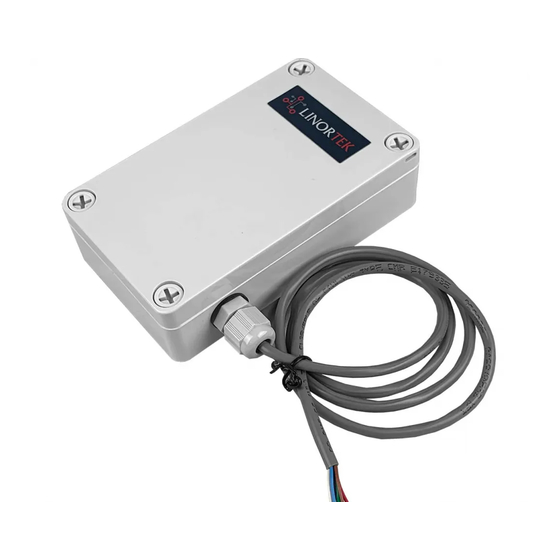
Thank you for purchasing the Linortek ITrixxWFMN Wireless Hour Meter. The iTrixx is an IoT controller and runtime meter with
digital inputs, analog inputs and relay outputs capable of tracking runtime hours of up to two different pieces of equipment. For the
complete setting instructions, please refer to the iTrixxWFMN Owners and Operation Manual, which can be downloaded here:
https://www.linortek.com/downloads/documentations/
W
'
B
HAT
S
IN
THE
OX
Please inspect the contents of your product kit. Each SERVER is sent in its own box and includes:
____One iTrixx WFMN SERVER
____One 12VDC Power Supply
____2 Wago Connectors
____One 2.2k Ohm Resistor Kit
____iTrixx WFMN Quick Setup Instruction
T
WFMN W
C
I
RIXX
IRE
HART
There is 1 cable on the iTrixxWFMNDi, and 3 cables on the iTrixxWFMNADi. From the top to bottom, they are marked as cable 1,
2, 3. See the chart below for explanation.
iTrixxWFMNDi Hardware
Cable 1: Analog Inputs (for iTrixxWFMNADi only)
Wire Color
Green
Brown
Red
White
Blue
Black
Cable 2: Relay Outputs (for iTrixxWFMNADi only)
Wire Color
Brown
Green
Red
Blue
White
Black
ITRIXXWFMN QUICK SETTING INSTRUCTION
Function
Ain1
Return
5V
Ain2
Return
5V
Function
Relay 1 NC
Relay 1 C
Relay 1 NO
Relay 2 NC
Relay 2 C
Relay 2 NO
iTrixxWFMNADi Hardware
Note
Analog 1
If 12V sensor, us a 12V power supply
Analog 2
If 12V sensor, us a 12V power supply
Note
Relay 1
Relay 2
1
Advertisement
Table of Contents

Related Manuals for Linortek ITRIXX-WFMN


Summary of Contents for Linortek ITRIXX-WFMN
- Page 1 ITRIXXWFMN QUICK SETTING INSTRUCTION Thank you for purchasing the Linortek ITrixxWFMN Wireless Hour Meter. The iTrixx is an IoT controller and runtime meter with digital inputs, analog inputs and relay outputs capable of tracking runtime hours of up to two different pieces of equipment. For the complete setting instructions, please refer to the iTrixxWFMN Owners and Operation Manual, which can be downloaded here: https://www.linortek.com/downloads/documentations/ B Please inspect the contents of your product kit. Each SERVER is sent in its own box and includes: ____One iTrixx WFMN SERVER ____One 12VDC Power Supply ____2 Wago Connectors ____One 2.2k Ohm Resistor Kit ____iTrixx WFMN Quick Setup Instruction WFMN W C RIXX HART There is 1 cable on the iTrixxWFMNDi, and 3 cables on the iTrixxWFMNADi. From the top to bottom, they are marked as cable 1, 2, 3. See the chart below for explanation. iTrixxWFMNDi Hardware iTrixxWFMNADi Hardware Cable 1: Analog Inputs (for iTrixxWFMNADi only) Note Wire Color Function Green Ain1 Analog 1 Brown Return If 12V sensor, us a 12V power supply White Ain2 Analog 2 Return Blue Black If 12V sensor, us a 12V power supply Cable 2: Relay Outputs (for iTrixxWFMNADi only) Note Wire Color...
- Page 2 Cable 3: Digital Inputs and Power Input Note Wire Color Function 1248VDC Power Input Black Ground Green DIN 1 A Input 1, 524VDC. If using a voltage above 12VDC for a digital input, you must use a 2.2K ohm resistor. White DIN 1 C Brown DIN 2 A Input 1, 524VDC. If using a voltage above 12VDC for a digital input, you must use a 2.2K ohm resistor. Blue DIN 2 C M CTIVATE ETER The ITrixxWFMN is designed to be integrated into existing equipment to monitor runtime. Installing your iTrixx will involve tapping circuits on the equipment you intend to monitor. The iTrixx Hour Meter has two separate hour counters. The hour counters may be activated in a number of different ways. 1. In the simplest setup the iTrixx may be activated whenever power is applied to the unit. In this case, if the iTrixx is on, it is counting. A voltage threshold is provided so the iTrixx may stop counting as power is lost to prevent memory corruption. In this way, you only need to connect the iTrixx to the same power source of the equipment you wish to collect running data, no other wiring required. 2. You may also use one of the inputs to turn counting on and off. There are two digital inputs in the iTrixx. The digital inputs allow iTrixx to detect an external on/off state of a sensor. To use the meter on a mobile equipment, a constant 1248VDC power source from a battery, and a separate 548VDC circuit that turns on and off with the vehicle. A constant power source is preferable to power your Wifi meter because it will always be on. If the meter has to boot up when your equipment is powered on, you may not have an accurate reading. The WiFi meter at idle draws approximately 70mA. It will not drain the battery unless it is left for an exceptionally long time. 3. Alternatively, it can be configured to follow one of the relays such that when the relay is activated the iTrixx will count (for iTrixxWFMNADi unit only). The relays on the iTrixxWFMNADi are dry contact relays and normally open. ...
- Page 3 NOT use external ground connections. Doing so may damage the SERVER or POE originating device. Once you are finished wiring the iTrixx to your equipment, you may then power on your equipment or reconnect the vehicle’s battery and configure your device. Y N ONNECT ETWORK 1. Before powering up the iTrixx To configure your iTrixx, you will need the following information during the setup process, we suggest you to gather that information before putting your device in Provissioning Mode, because once you put your device in Provisioning Mode, you will have 2 minutes to connect it to your network before this mode times out. 1) Your network name and your WiFi password. 2) Write down the last 6 characters of your device’s MAC address, this will be the password to login to your iTrixx server when you config the software on Telnet. You can find the MAC address at the back of your device. 3) Download the HourCollector desktop App from our website download page, this free tool can help you to find the IP address on your network, as well as for data collection/monitoring. Before downloading, ensure your computer has Java installed. Java is available for download here: https://www.java.com/en/. The Hour Collector app will automatically locate your iTrixx and allows for quick access. The Hour Collector app will not immediately locate the iTrixx if not connected via Ethernet. The iTrixx will appear once the HourCollector updates after receiving data from iTrixx devices. The HourCollector app updates every two minutes by default. You can download this tool here: https://www.linortek.com/downloads/supportprogramming/ 4) Open Telnet on your PC: You will need to use a Telnet client to configure your iTrixx server. To configure Telnet on Windows 8.1 or Windows 10, follow the steps below: • Open Control Panel • Select Programs • Under Programs and Features select Turn Windows features on or off • Scroll down and select the checkbox for Telnet Client and click OK 5) You will need to use your web browser to connect the iTrixx Server to your network, since the iTrixx config page is not encrypted,you will need to make sure when you put the config link http://wifihmconfig.com on your browser, and the browser will NOT change to https://wifihmconfig.com, otherwise, you can’t connect. Here are some samples how to change your browser settings in order to connect to the config page: • On Google Chrome, you can go to SettingsPrivacy and SecuritySafe Browsing, select No Protection. • On Firefox, go to Privacy & Security Setting, scroll down to the page, on HTTPSOnly Mode, select Don’t Enable HTTPSOnly Mode. • For other browsers, you can add wifihmconfig.com to your browser unprotected site so that you can access the config page. 2. Powering iTrixx Your iTrixx server is supplied with a 12VDC power supply. You may power your iTrixx server using this power supply for initial setup and software configuration. Once your initial setup is completed, you can wire your iTrixx to your equipment by tapping into a 12 – 48 VDC circuit on your equipment. ...
- Page 4 on Cable 3 to the negative wire (marked with white strip) on the power supply. Once powered, your iTrixx server is ready to be connected to your network. 3. Connecting iTrixx to WiFi Network After powering up the iTrixx server, you then need to connect it to your network. To connect, follow the steps below: 1) Open the cover of the iTrixx, locate the DFLT button, push and hold the DFLT button with a paper clip until the blue LED starts flashing. Your device is now in Provisioning Mode. You have 2 minutes to configure connect to your network before this mode times out. Once the Provisioning mode times out, you will need to repeat the first step and put it in Provisioning mode. 2) Use a WiFi enabled PC or a mobile device to connect to your server’s AP (WiFi enabled device is only required for the initial setup, once you have connected your iTrixx to your network, you can use any PC on the same network to config the device). If you use a PC, click the Network icon at the right side corner, the iTrixx will be displayed as a WiFi network named WiFiHM_xx:xx:xx (The x’s make up the last 6 characters of your device’s MAC address) 3) When prompted enter the password: wifihmpsk 4) Once connected you may receive a message stating there is no internet connection. Disregard this message. 5) Using your web browser, type in this UR: http://wifihmconfig.com. Note: Please make sure your browser doesn’t change http to https! 6) Enter the name of your WiFi network under Network Name and your WiFi password under Pass phrase 7) Click Connect. The Blue LED on your device will stop blinking and stay on solid. Your iTrixx server is now connected to your network, at this time, your computer should connect back to your network. If it’s not automatically switched to your network, click the network icon on your computer, and select the same network your iTrixx connected to in our previous step. Troubleshooting: If you are unable to connect the iTrixx to your WiFi network (error message: reject to connect), this is because your WiFi security blocks unrecognized SSIDs, please contact your IT department to whitelist the SSID for the iTrixx device. WiFi Connection Page Network List Sample IP ADDRESS Before using Telnet to config to your iTrixx, you will need to find its IP address from your network. The easiest way to find your server’s IP address is by using the Linortek Hour Collector app. Once you open the HourCollector App, it will display all iTrixx devices that you have installed on the same network. If you can’t find the IP address, press the RESET button with a paper clip and it will identify upon reboot. You may also find your device’s IP address by signing on to your router and searching the list of connected devices. Your iTrixx hour meter will be identified on your router as WiFiHM_xxxxxx where the x’s are the last 6 characters of the device’s MAC address. The Hour Collector app will display the following information:...
- Page 5 T ROGRAM RIXX FROM ELNET You will need to use a Telnet client to configure your iTrixx server. To configure Telnet on Windows 8.1 or Windows 10, follow these steps: 1) Open Control Panel 2) Select Programs 3) Under Programs and Features select Turn Windows features on or off 4) Scroll down and select the checkbox for Telnet Client and click OK To connect to the iTrixx server using your PC, follow these steps: 1) Search Command Prompt on your search bar (Windows 10), click and open Command Prompt 2) Enter telnet nnn.nnn.nnn.nnn 30316 where n is your device’s IP address 3) Once connected, it will prompt you for a password. By default, this password is the last 6 characters of its MAC address – without colons and all lower case– which can be found printed on the enclosure or the HourCollector App. (ex: cd56ef) 4) After entering your password, all available commands will be listed in the command prompt window. For details of how to use the commands, please refer to the manual Appendix 1: Available Commands. You can also download a TCP Telnet app for a mobile device to be able to send Telnet commands to the WFMN provided the mobile device is also connected to the same WiFi network (does not work on cellular network). S B C RIXX ERVER ASIC ONFIGURATION To configure your server, you will need to issue commands via the Telnet terminal. This section will cover the basic configuration of your device. For a full list of commands and syntax, see the following pages. IMPORTANT NOTE: Make certain to use the save command after making changes otherwise your changes will be lost when your server reboots. 1. Naming your server To make your iTrixx server more identifiable on your network, enter server=<name> replacing <name> with your desired server name. 2. Setting Time and Date By default, your server is configured for GMT. To adjust the time zone, enter timezone=x where x is your time zone offset. For example: timezone=5 for EST, timezone=4 for EDT if you are in Eastern DayLight Saving time. To check your server’s time, you may enter the command: time. This will display the current time and date formatted as: yyyymmddThhmmss followed by the time zone offset (ISO 8601). For example: 20200422T1330000400 for 4/22/2020 1:30pm GMT4.
- Page 6 S ONTACT UPPORT If you need assistance on setting your devices, please feel free to contact us: Phone: (001)3364856199 Email: support@linortek.com You can also start a chat from our website to reach our support teams. 0150800010C Winston Salem, NC 27127 1021 R003V003 i nfo@linortek.com www.linortek.com Printed in U.S.A. Information subject to change without notice.
Need help?
Do you have a question about the ITRIXX-WFMN and is the answer not in the manual?
Questions and answers