
Related Manuals for Linortek iTrixx-Ultra 300


Summary of Contents for Linortek iTrixx-Ultra 300
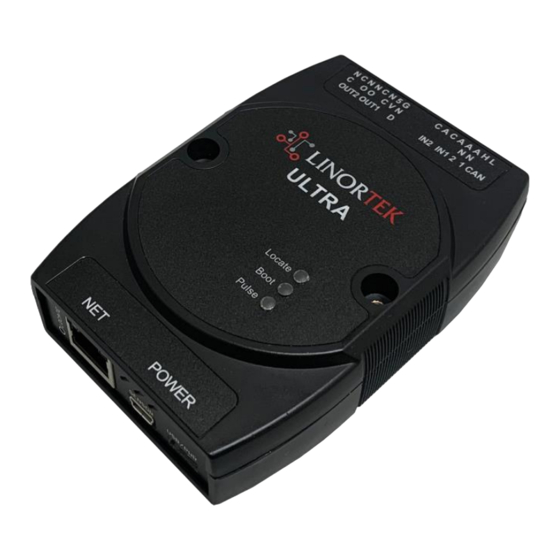
- Page 1 300 User Manual www.linortek.com Preliminary For Ultra 300 with Hour Meter Software...
-
Page 3: Table Of Contents
Contents LINORTEK ONE-YEAR LIMITED WARRANTY ..........................5 End-User License Agreement for Linortek Software and Documentation ................7 Getting Started ..................................9 Activate the Meter ................................10 Wiring the Server ................................10 Board Layout Reference ..............................10 Power Connection ................................11 Network Connection ................................. - Page 4 System ....................................33 Load/Reboot System Page ............................33 Data Collection ..................................35 Hour Collector App ................................35 DataCollector Pro App ..............................35 RESTful API ..................................35 MQTT....................................35 JSON file .................................... 35...
-
Page 5: Linortek One-Year Limited Warranty
(“Warranty Period”) when used in accordance with the operating instructions. A copy of a retail receipt is required as proof of purchase. If a hardware defect arises and a valid claim is received within the Warranty Period, at its option and to the extent permitted by law, Linortek will either (1) repair the hardware defect at no charge, using new or refurbished replacement parts, (2) exchange the product with a product that is new or which has been manufactured from new or serviceable used parts and is at least functionally equivalent to the original product, or (3) refund the purchase price of the product. - Page 6 It is important that you use licensed electricians and comply with electrical codes that are applicable to your location. These codes exist for your safety, as well as the safety of others. Linortek assumes no responsibility for any harm or damage resulting from a failure adhere to local laws, ordinances or regulations or...
-
Page 7: End-User License Agreement For Linortek Software And Documentation
5. Termination. This EULA is effective from the date you first use the Software and will continue for as long as you own the Linortek Product associated with it or until you or Linortek terminate this agreement under this section. You may terminate this EULA at any time upon written notice to Linortek at the address provided below. Linortek may terminate this EULA at any time if you fail to comply with any of the terms in this agreement. - Page 8 You also agree that the United Nations Convention on Contracts for the International Sale of Goods shall not apply. You agree that regardless of any statute or law to the contrary, any cause of action against us arising out of or related to the Linortek website, the Software or the Linortek Products must commence within one (1) year after the cause of action accrues or such cause of action shall be permanently barred.
-
Page 9: Getting Started
Getting Started Thank you for purchasing the Linortek ITrixx-Ultra 300. The Ultra 300 is an IoT controller and run-time meter. The Ultra 300 is equipped with two meters on the software that you can use to track equipment usage or uptime/downtime or as a counter. -
Page 10: Activate The Meter
Activate the Meter The iTrixx Hour Meter software has two separate hour counters with independent triggers. The hour counters may be activated in a number of different ways. 1. In the simplest setup the METER may be activated whenever power is applied to the unit. In this case, if the SERVER is on, it is counting. -
Page 11: Power Connection
Relay outputs: 2 relay outputs, ignal relay, 1 Form C, 1A @ 30VDC, #2 on the left Voltage output: This is used to drive external devices such as a sensor. The voltage supplied depends on what power source is used to power the ULTRA SERVER. Digital inputs: 2 digital inputs, 5VDC-48VDC (24VDC-48VDC must use the external resistor), #2 on the left Analog inputs: 2 analog inputs, isolated, #2 on the left CAN inputs (software not yet implemented) -
Page 12: Voltage Output Connection
The relays have 3 terminals labelled NO, C and NC which stand for Normally Open, Common and Normally Closed. When activated, the relay moves the connection from C-NC to C¬NO. If you want to make a connection when the relay is activated, connect your wires between C and NO. -
Page 13: Accessing The Server
Use of Chrome & Firefox browsers is recommended. Please note: If you prefer to use Internet Explorer, Internet Explorer saves Linortek Discoverer as a Zip file by default. In order to use the Discoverer, you will need to select Save as and rename the file as Linortek Discoverer.jar when you download. -
Page 14: Finding The Ip Address By Connecting To Usb Port On Your Pc
Click the device you want to use shown on the Discoverer program to launch the SERVER’s web pages in your browser. Click the Login button on the homepage. Default username/password is: admin/admin. You may change these as you desire or disable this feature in the settings menu. -
Page 15: Software Configuration
This page is static with no background activity and is a useful place to park if you are not using the SERVER and do not want to close the connection. The Ultra 300 has a different landing page from most Linortek devices. In addition to the normally displayed information, this page also displays the data from each of the two meters on your device. -
Page 16: Services
• TIME - Displayed along with the day of the week. This time may be set to be in a 12-hour format with AM/PM indicator or 24-hour format. • DATE – Current date is displayed here. • VOLTS – Voltage at the board is displayed. This may be useful if the SERVER is powered along with other equipment, voltage variance can be noted. - Page 17 Select Services – In/Out, the In/Out page is displayed below. The In/Out page has the relay controls and the input controls on one page. The Ultra 300 SERVER has two relay outputs, two digital inputs and two analog inputs. The relay is named as Relay 1 and Relay 2, digital input is named DIN1 and DIN2, analog input is named AN1 and AN2, you can change the names as desired.
- Page 18 Normal - relay physically on the SERVER • Latched - not currently supported • Remote - a relay on another Linortek device access over the network • Zigbee - a relay at a remote device access over an RF system •...
- Page 19 At the top of each input is a label (ex: DIN 1, AIN 2) specifying whether it is a digital input (DIN) or analog input (AIN) as well as the input number. This label will turn green when the input is enabled. Inside the Box will be any display configured from the Set Input page (see the pages below for the input setting details).
- Page 20 • Value - These are Min/Max values used for the display. This is useful for preventing a Meter from going past its end or setting the value of a VBar. This is the Value after the Corrector. The system cannot display a value past Max so be sure this is at least set to 1.
- Page 21 • AC Current 1 - AC current sensor 1 input from Ultra (AC current sensor connected to AIN1) • AC Current 2 - AC current sensor 2 input from Ultra (AC current sensor connected to AIN2) • AC Current 3 - Not used •...
-
Page 22: Hours Page
Hours Page After wiring your SERVER into your equipment and setting your trigger, you now need to activate & configure the hour meter. To reach the Hour Meter page, navigate to the Services dropdown menu and select Hours. On this page there are two identical columns;... -
Page 23: Tasks
13. Count Hours By - Each meter can record 999999.99 hours, decimal hours with 1/100 hour by default, you can change it to 1/10 if desired. Tasks The TASKS page displays the automatic events that can be programmed into the SERVER. You can schedule up to 32 condition-logic events in the SERVER. - Page 24 • Schedule Select - Determined by clicking on a schedule line from the previous page. • Schedule Name - Enter a 15-character Schedule Name. • USE - In order for a Schedule line to be active you must select the USE button. If there is an error detected in entering Schedule data, the USE box will automatically uncheck.
- Page 25 • Data B - Select Data B for the above device. Depending on the device selected the Data used for testing may have special properties. See above list. • Device C - is what to control. • Data C – Set property for Device C. Syntax is used as follows: •...
-
Page 26: Logs
Reset the Meter Automatically Using the Task In some cases, you might need to reset the meter at regular time, for example, daily. You can do so by setting a task on the TASKS page. Below is an example to reset meter#2 every day at 12:00am. Logs The Logs tab displays over 10,000 entries from actions taken by the SERVER or by users themselves. -
Page 27: Settings
Settings User and Admin Credentials Page Use this page from the Settings drop down menu. Here you can set up to 3 users for your Ultra 300 system. As a default only User 1 is Active. Here you can: • User Name and Password - Each user has their own credentials. -
Page 28: Settings Page
• Date - Set date using a yy/mm/dd format. • Time Zone - Set desired time zone. -5 for EST, -8 for PST, you can now add a :mm for setting part hour, for example, 5:30 is a time zone at 5 hours and 30 minutes. •... -
Page 29: Configure
• Select theme – Choose theme color: red/green/blue • Change Logo – Choose your Company’s Logo to replace Linortek logo (max size: 60kB, format: .png file) Configure Dynamic DNS Page Access this page from the Configure dropdown menu. From this page you can assign dynamic DNS settings. This page, along with proper port forwarding through the router, can enable global access to a device behind a NAT router or firewall. -
Page 30: Email Setup Page
Email Setup Page Setup an email account for the SERVER to use in sending email messages from various modules. Access this page from the Configure tab. • SMTP Server – Enter the outgoing mail server that you want to use. •... -
Page 31: Network Configuration Page
• MQTT Server: This section refers to the IP address that the MQTT Broker is hosted on. For example, a company may have a computer that runs the MQTT Broker, and all devices that want to connect to that broker needs its IP Address. In this example, the Broker’s IP address is “192.168.1.10”. -
Page 32: Ip Range Configuration Page
Access this page from the Configure dropdown menu. These settings allow the SERVER to remotely control the relays on other Linortek devices (Peer-to-Peer communication). This is done by selecting the Remote Device in the Schedule program or by setting up a relay as a REMOTE. There are 8 possible REMOTE locations. - Page 33 System The System page is used for software update or reset the software to factory default if needed. Load/Reboot System Page Click System – Load/reboot System, from here you can upload the software file if you need to update the software on your SERVER, or reset the device to factory default if needed.
- Page 34 get a message “MPFS Updated Successful”, then click the “Site main page”, you will be directed to the Login page. On the bottom of every page, you can see your Webpage Software version.
- Page 35 MQTT broker. For more information about the features for the app, as well as how to use the data saved by the app, please refer to the Linortek DataCollector App Setting Instruction, which can be downloaded from our website Download page at: https://www.linortek.com/downloads/documentations/...
Need help?
Do you have a question about the iTrixx-Ultra 300 and is the answer not in the manual?
Questions and answers