Planet MGSW Series Quick Installation Manual
Managed metro ethernet switch
Hide thumbs
Also See for MGSW Series:
- Quick installation manual (16 pages) ,
- Quick installation manual (19 pages)
Table of Contents
Advertisement
Quick Links
Advertisement
Table of Contents

Subscribe to Our Youtube Channel
Related Manuals for Planet MGSW Series


Summary of Contents for Planet MGSW Series
- Page 1 Managed Metro Ethernet Switch MGSW/MGSD Series Quick Installation Guide...
-
Page 2: Table Of Contents
Table of Contents 1. Package Contents ..................3 2. Requirements ..................... 4 3. Wiring DC Power Inputs ................5 4. Terminal Setup ................... 6 4.1 Logging on to Console ................. 7 4.2 Configuring IP Address ................. 8 4.3 Storing Current Switch Configuration ............. 9 5. Starting Web Management .................10 5.1 Logging in to the Managed Metro Switch ..........10 5.2 Saving Configuration ................13 6. Recovering Back to Default Configuration .............14... -
Page 3: Package Contents
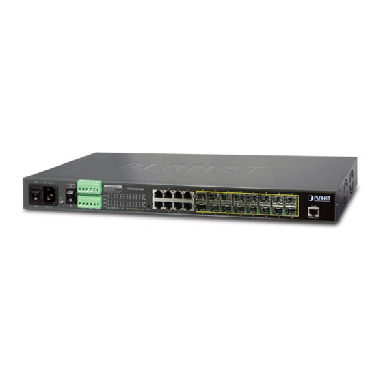
1. Package Contents Thank you for purchasing PLANET L3 and L2+ Managed Metro Ethernet Switches. The descriptions of these models are shown below: L3 24-port 100/1000BASE-X SFP + 4-port 10G SFP+ Managed MGSW-28240F Metro Ethernet Switch L2+ 16-port 100/1000BASE-X SFP + 8-port Gigabit TP Managed MGSW-24160F Metro Ethernet Switch L2+ 8-port 100/1000X SFP + 2-port 10/100/1000T Managed MGSD-1008F Metro Ethernet Switch “Managed Metro Switch” is used as an alternative name in this Quick Installation Guide. Open the box of the Managed Metro Switch and carefully unpack it. The box... -
Page 4: Requirements
2. Requirements z Workstations running Windows 10/XP/2003/Vista/7/8/2008, MAC OS X or later, Linux, UNIX, or other platforms are compatible with TCP/IP protocols. z Workstations are installed with Ethernet NIC (Network Interface Card) z Serial Port Connection (Terminal) The above workstations come with COM port (DB9) or USB-to-RS232 converter. The above workstations have been installed with terminal emulator, such as Tera Term, PuTTY or Hyper Terminal included in Windows XP/2003. -
Page 5: Wiring Dc Power Inputs
3. Wiring DC Power Inputs The Front Panel of the Managed Metro Switch indicates a DC inlet power socket and consists of one terminal block connector within 6 contacts. Please follow the steps below to insert the power wire. 100~240V AC DC POWER MGSD-10080F 1000... -
Page 6: Terminal Setup
4. Terminal Setup To configure the system, connect a serial cable to a COM port on a PC or notebook computer and to the DB9 type of serial port of the Managed Metro Switch. PC / Workstation with Terminal Emulation Software Managed Switch RS232 to RJ45 Cable Serial Port RJ45 Console Port Figure 4-1: Managed Metro Switch Console Connectivity A terminal program, such as Tera Term or PuTTY, is required to make the software connection to the Managed Metro Switch. -
Page 7: Logging On To Console
4.1 Logging on to Console Once the terminal is connected to the device, power on the Managed Metro Switch, and the terminal will display “running testing procedures”. Then, the following message asks to log in user name and password. The factory default user name and password are shown as follows and the login screen in Figure 4-3 appears. Username: admin Password: admin Figure 4-3: Managed Metro Switch Console Login Screen The user can now enter commands to manage the Managed Metro Switch. For a detailed description of the commands, please refer to the following chapters. -
Page 8: Configuring Ip Address
4.2 Configuring IP Address The Managed Metro Switch is shipped with default IP address shown below. IP Address: 192.168.0.100 Subnet Mask: 255.255.255.0 To check the current IP address or modify a new IP address for the Switch, please use the procedures as follows: Showing the Current IP Address 1. At the “#” prompt, enter “show ip interface brief”. 2. The screen displays the current IP address as shown in Figure 4-4. Figure 4-4: IP Information Screen Configuring IP Address 3. At the “#” prompt, enter the following command and press <Enter> as shown in Figure 4-5. -
Page 9: Storing Current Switch Configuration
The previous command would apply the following settings for the Managed Metro Switch. IP Address: 192.168.1.100 Subnet Mask: 255.255.255.0 4. Repeat step 1 to check if the IP address is changed. If the IP is successfully configured, the Managed Metro Switch will apply the new IP address setting immediately. You can access the Web interface of the Managed Metro Switch through the new IP address. -
Page 10: Starting Web Management
5. Starting Web Management The following shows how to start up the Web Management of the Managed Metro Switch. Note the Managed Metro Switch is configured through an Ethernet connection. Please make sure the manager PC must be set to the same IP subnet address. - Page 11 Default IP Address: 192.168.0.100 Default Username: admin Default Password: admin Figure 5-2: Login Screen 3. After entering the password, the main screen appears as Figure 5-3 shows. Figure 5-3: Web Main Screen of Managed Metro Switch...
- Page 12 The Switch Menu on the top of the Web page lets you access all the commands and statistics the Managed Metro Switch provides. The Switch Menu always contains one or more buttons, such as “Refresh”, “Save”, “Help” and “Logout”. Figure 5-4: Switch Menu Figure 5-5: Switch Menu - System If you are not familiar with Switch functions or the related param- eter, press “Help icon”...
-
Page 13: Saving Configuration
5.2 Saving Configuration To save all applied changes and set the current configuration as a startup configuration on the Web user interface, the startup-configuration file will be loaded automatically across a system reboot. 1. Click the Save icon on the top Switch Menu bar. 2. Press the “Save Configuration” button. 3. -
Page 14: Recovering Back To Default Configuration
6. Recovering Back to Default Configuration IP address has been changed or admin password has been forgotten – To reset the IP address to the default IP address “192.168.0.100” or reset the login password to default value, press the hardware-based reset button on the front panel for about 10 seconds. After the device is rebooted, you can log in the management Web interface within the same subnet of 192.168.0.xxx. -
Page 15: Customer Support
7. Customer Support Thank you for purchasing PLANET products. You can browse our online FAQ resource and User’s Manual on PLANET Web site first to check if it could solve your issue. If you need more support information, please contact PLANET switch support team. PLANET online FAQs: http://www.planet.com.tw/en/support/faq Switch support team mail address: support@planet.com.tw MGSW / MGSD series User’s Manual: https://www.planet.com.tw/en/support/downloads?&method=keyword&keyword=M GS&view=3#list (Please select your switch model name from the drop-down menu of Product Models.) Copyright © PLANET Technology Corp. 2018.
Need help?
Do you have a question about the MGSW Series and is the answer not in the manual?
Questions and answers