Table of Contents
Advertisement
Quick Links
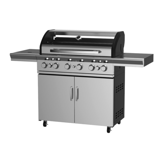
AVENIR
6 BURNER BBQ
Model No. GM172-054
Enhance your outdoor area with a Gasmate Avenir 6
burner BBQ complete with rear ceramic rotisserie burner
Create the ultimate outdoor kitchen by adding a
Gasmate Avenir Sink, Storage and/or Fridge Module to
your BBQ (sold separately)
Double skinned 304 grade stainless steel roasting
hood with viewing window and temperature gauge
304 grade stainless steel fascia, side shelves and
cabinet doors with powder coated cabinet trolley
Gasmate® is a registered trademark of: Sitro Group Australia Pty Ltd www.gasmate.com.au
Important: Retain these instructions for future use.
Flush mounted side burner for greater cooking versatility
Cast iron hotplates and grill with enamel warming rack
Stainless steel tubular burners lit by electronic ignition
Complete with hose and regulator
Assembled dimensions (mm): 1700W x 1180H x 580D
Total cooking area (mm): 960W x 460D
Approved to Australian and New Zealand Standards
Aber Living - Hamilton, N.Z. www.gasmate.co.nz
5201-07/20
Advertisement
Table of Contents

Related Manuals for Sitro Group Gasmate AVENIR


Summary of Contents for Sitro Group Gasmate AVENIR
- Page 1 304 grade stainless steel fascia, side shelves and cabinet doors with powder coated cabinet trolley Important: Retain these instructions for future use. Gasmate® is a registered trademark of: Sitro Group Australia Pty Ltd www.gasmate.com.au Aber Living - Hamilton, N.Z. www.gasmate.co.nz 5201-07/20...
-
Page 2: General Information
GENERAL INFORMATION If you are unable to correct the leak by tightening the connections, turn off the gas and contact the supplier IMPORTANT immediately. Read these instruction carefully prior to use. Always ensure the barbecue is kept away from flammable Familiarise yourself with the appliance before materials and the gas cylinder clear of any heat source. - Page 3 GENERAL INFORMATION FOR YOUR SAFETY • This barbecue must not be used indoors. • Only use in well ventilated areas. Failure to comply with these instructions could result in a fire or explosion which could cause serious • CARBON MONOXIDE HAZARD - USING THIS bodily injury, death or property damage.
-
Page 4: Protect Children
GENERAL INFORMATION Location of your Barbecue Tools You Will Need DO NOT use your barbecue in garages, porches, Standard Phillips-head screw driver (or cordless drill breezeways, sheds or other enclosed areas. Your and bits) and Adjustable spanner (open ended shifter) or barbecue is to be used OUTDOORS. -
Page 5: Exploded Diagram
EXPLODED DIAGRAM No. Description No. Description No. Description Fire Box Fat tray bracket Crossfire Bottom shelf Fat tray Big control knob Swivel Castor Fat tray front fascia Small control knob Locking Swivel Castor R/H side shelf assembly Ignitor Left side panel L/H side burner assembly Side burner Right side panel... - Page 6 ASSEMBLY INSTRUCTIONS STEP 1 Use 16x M6x15mm screws (A) and 16x M6 spring washers (E) to attach 2x swivel castors (3) and 2x locking swivel castors (4) to the base panel (2). STEP 2 Use 4x M6x12mm screw (B) to attach cabinet left side panel (5) and cabinet right side panel (6) to the base panel (4). Use 2x M4x12mm screw (D) attach Upper door bracket (7).
- Page 7 ASSEMBLY INSTRUCTIONS STEP 3 Use 5x M6x12mm screws (B) to attach cabinet back panel (8). Note: DO NOT tighten the screws of this step now. STEP 4 Use 4x M6x12mm screws (B) to attach cabinet horizontal shelf (9).
- Page 8 ASSEMBLY INSTRUCTIONS STEP 5 Use 4x M6x12mm screws (B) to attach the door handle (12) to door (10,11). STEP 6 Attach doors (10,11) to completed cabinet by inserting the bottom door locator into holes, then pressing down on the top locator insert them into top door locator.
- Page 9 ASSEMBLY INSTRUCTIONS STEP 7 Use 6x M6x12mm screws (B) to attach the flat tray bracket (13) to main cabinet. STEP 8 Attach hose and gas regulator assembly (23) to firebox assembly (1). Use 4x M6x12mm screws (B) to attach firebox to the cabinet, making sure that the locators insert into the base of the firebox (1).
- Page 10 ASSEMBLY INSTRUCTIONS STEP 9 Use 3x M5x12mm screws (C) to attach the flat tray front fascia (15) to the flat tray (14). STEP 10 Use 4x M6x15mm screws (A) leaving a 5mm gap & 1x M5x12mm screw (C) to attach the R/H side shelf assembly (16) to the firebox.
- Page 11 ASSEMBLY INSTRUCTIONS STEP 11 Use 4x M6x15mm screws (A) leaving a 5mm gap & 1x M5x12mm screw (C) to attach the L/H side burner assembly (17) to the firebox. Tighten both side shelves. STEP 12 Attach the main gas line to side burner using an adjustable spanner.
- Page 12 ASSEMBLY INSTRUCTIONS STEP 13 Insert side burner grid (18). STEP 14 Insert 4x flame tamers (19).
- Page 13 ASSEMBLY INSTRUCTIONS STEP 15 Insert the ignition wire into the end of the ignition pin. Note: Ensure that the side burner body is located over the injector. STEP 16 Insert 2x cooking grills (20) and 1x hotplate (21) into firebox.
- Page 14 ASSEMBLY INSTRUCTIONS STEP 17 Insert warming rack (22). STEP 18 Insert AA battery into the ignition pack with battery facing the correct way (+ facing out).
- Page 15 ASSEMBLY INSTRUCTIONS STEP 19 STEP 20 Step 12 Step 12 Step 13 Step 13 Step 12 Step 13 Attach the regulator to your gas cylinder. Attach the regulator to your gas cylinder. Step 12 Turn on the gas cylinder ensuring that all of the Turn on the gas cylinder ensuring that all of the Attach the regulator to your gas cylinder.
-
Page 16: General Assembly
GENERAL ASSEMBLY Connecting & Disconnecting to Gas Source Regulator Safety Feature Familiarize yourself with the general information and All QCC regulators (the part that attaches to the gas safety guidelines located at the front of this manual. cylinder to regulate the flow of gas) have a safety feature included that restricts gas flow in the event of a gas leak. -
Page 17: Lighting Procedure
LIGHTING PROCEDURE Burner Operation & Ignition System Check 9. Adjust the heat by turning each control knob to the “HIGH”/”LOW” position. 1. Open the hood of the barbecue before attempting to 10. To turn the barbecue ‘OFF’ turn the cylinder valve to light the burners. -
Page 18: Operating Procedure
OPERATING PROCEDURE Burn Off Cooking Surfaces meat to spit rod and place rod into barbecue using indentations in the sides of the fire box. Place a shallow We recommend operating your barbecue on its highest cooking dish or aluminium foil dish underneath the setting for 15-20 minutes prior to first use. -
Page 19: Care And Maintenance
CARE & MAINTENANCE Care of Cooking Surface As with all appliances, proper care and maintenance will keep them in top operating condition and prolong Use and care of the cooking surface is important. Do not their life. Your new gas barbecue is no exception. By use pans on the cooking surface. -
Page 20: Safe Appliance Locations
SAFE APPLIANCE LOCATIONS Within a partial enclosure that includes an overhead cover and no more than two walls This appliance shall only be used in an above ground (see Example 2 & 3). open-air situation with natural ventilation, without Within a partial enclosure that includes an overhead stagnant areas, where gas leakage and products of cover and more than two walls, the following will apply: combustion are rapidly dispersed by wind and natural... - Page 21 This page has been left intentionaly blank...
- Page 22 This page has been left intentionaly blank...
- Page 23 This page has been left intentionaly blank...
-
Page 24: Limited Warranty
2 YEAR LIMITED WARRANTY Aber Living warrants the purchaser of this product against defects in workmanship and material, for a period of up to 24 months from the date of purchase. The warranty is non-transferable and becomes void if used for commercial or rental purposes.
Need help?
Do you have a question about the Gasmate AVENIR and is the answer not in the manual?
Questions and answers