Table of Contents
Advertisement
Quick Links
Advertisement
Table of Contents

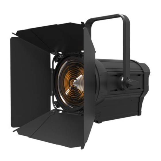
Summary of Contents for ACME Theatre Sport 150
-
Page 2: Table Of Contents
CONTENTS 1. Safety Instructions ..................2 2. Technical Specifications ................. 4 3. The Plate for Color Filter & Barn Door Installation ......... 5 4. How To Set The Unit ..................6 4.1 Control Panel ................... 6 4.2 Main Functions ..................7 5. -
Page 3: Safety Instructions
1. Safety Instructions Please read the instruction carefully which includes important information about the installation, usage and maintenance. WARNING Please keep this User Guide for future consultation. If you sell the unit to another user, be sure that they also receive this instruction manual. Important: Damages caused by the disregard of this user manual are not subject to warranty. - Page 4 Unit’s surface temperature may reach up to 41℃. DO NOT touch the housing bare-handed during its operation. Avoid any inflammable liquids, water or metal objects entering the unit. Once it happens, cut off the mains power immediately. DO NOT operate in dirty or dusty environment, do clean fixtures regularly. ...
-
Page 5: Technical Specifications
2. Technical Specifications Power Voltage: AC 100~240V, 50/60Hz Power Consumption: 190W Light Source: TS-150 CW/TS-1504 CW: C117C1222-150-011 TS-150 WW/TS-150 WW-W/TS-1504 WW: C117W1222-150-011 Color Temperature: 3150±150K, 5600±150K(optional) Optical: CRI: WW≥94, CW≥90 CQS: WW≥94, CW≥91 TLCI: WW≥96, CW≥96 Control: DMX Channel: 2/3 Channels Mode Control Mode: DMX, Art-Net, Primary/Secondary, Manual Firmware Upgrade: Update via DMX link Construction:... -
Page 6: The Plate For Color Filter & Barn Door Installation
Dimensions/Weight: 437x340x417mm, 8.6kgs 17"x13"x16"in, 19lbs Photometric Diagram: Distance(m) ° ° ° 14 Lux 6920 2300 1175 6240 2380 1215 ° 55 Lux 2240 2000 3. The Plate for Color Filter & Barn Door Installation Fig. 1 At first, please push the Lock Cap button by hand as the arrow ①, and move away the Lock as the arrow ②;... -
Page 7: How To Set The Unit
Fig. 2 Secondly, please insert the Barn Door into the outside slot from topside as arrow ④, and fasten the lock (Note: the Barn Door must be fastened into the inside of the lock’s hook ); then flip down the lock cap again as arrow⑤. 4. -
Page 8: Main Functions
3. Button: MENU To select the programming functions DOWN To go forward in the selected functions To go backward in the selected functions ENTER To confirm the selected functions 4. DIMMER: Automatically adjust the dimmer value 5. ZOOM: Automatically adjust the zoom value 6. - Page 9 DMX Setting Select DMX Setting, press ENTER button to confirm, use UP/DOWN button to select DMX Address, Art-Net Setup or Channel Mode. DMX Address Select DMX Address, press the ENTER button to confirm. Use the UP/DOWN button to adjust the DMX address from 1 to 511/510.
- Page 10 Art-Net Setup Select Art-Net Setup, press the ENTER button to confirm. Use the UP/DOWN button to select Ethernet IP Setup or Art-Net Port Setup. Once selected, press the ENTER button to save. Select Ethernet IP Setup, press the ENTER button to confirm. Use the UP/DOWN button to select IP Address or Subnet Mask.
- Page 11 Square Law: Light intensity control is finer at low levels and coarser at high levels. Inverse Square Law: Light intensity control is coarser at low levels and finger at high levels. Linear: The increase in light intensity appears to be linear as DMX value is increased. S-Curve: Light intensity control is finger at low levels and high levels and coarser at medium levels.
- Page 12 Invert Display Select Invert Display, press the ENTER button to confirm. Use the UP/DOWN button to select the No(normal display) or Yes(inverse display), press the ENTER button to save. Press the MENU button back to the last menu or let the unit idle 30 seconds to exit menu mode. Language Select Language, press the ENTER button to confirm.
-
Page 13: Control By Universal Dmx Controller
Reset Select Reset, press the ENTER button and the fixture will now reset. 5. Control By Universal DMX Controller 5.1 DMX512 Connection 1. At last unit, the DMX cable has to be terminated with a terminator. Solder a 120-ohm 1/4W resistor between pin 2(DMX-) and pin 3(DMX+) into a 3-pin XLR-plug and plug it in the DMX-output of the last unit. -
Page 14: Address Setting
6. 3 pin XLR connectors are more popular than 5 pins XLR. 3 pin XLR: Pin 1: GND, Pin 2: Negative signal (-), Pin 3: Positive signal (+) 5 pin XLR: Pin 1: GND, Pin 2: Negative signal (-), Pin 3: Positive signal (+), Pin4, Pin5 not used. 5.2 Address Setting If you use a universal DMX controller to control the units, you have to set DMX address from 1 to 512 so that the units can receive DMX signal. -
Page 15: Troubleshooting
2 Channels (Mode 1): CHANNEL VALUE FUNCTION DIMMER 000-255 0%100% ZOOM 000-255 0%100% 3 Channels (Mode 2): CHANNEL VALUE FUNCTION DIMMER 000-255 0%100% 000-255 DIMMER FINE ZOOM 000-255 0%100% 6. Troubleshooting Following are a few common problems that may occur during operation. Here are some suggestions for easy troubleshooting: A. -
Page 16: Fixture Cleaning
5. Check to see if the DMX cables run near or run alongside to high voltage cables that may cause damage or interference to DMX interface circuit. C. One of the channels is not working well 1. The stepper motor might be damaged or the cable connected to the PCB is broken. 2. - Page 20 Innovation, Quality, Performance...


Need help?
Do you have a question about the Theatre Sport 150 and is the answer not in the manual?
Questions and answers