Table of Contents
Advertisement
Original instructions
Part C: LK6 and LK8 transmitting units
1
description ............................................................................................................ 2
2
Technical data ....................................................................................................... 3
3
Technical data sheet ............................................................................................. 3
4
Plates ..................................................................................................................... 4
4.1 Plates on LK6 and LK8 units in a radio remote control ..................................... 4
5
Light signals .......................................................................................................... 5
6
General operating instructions ............................................................................ 7
6.1 Starting up the radio remote control ................................................................. 7
6.2 Command activation ........................................................................................ 9
6.3 Data Feedback Function .................................................................................. 9
6.4 Radio link interruption ...................................................................................... 9
6.5 Transmitting unit automatic switch off .............................................................. 9
6.6 Switching off the transmitting unit ................................................................... 10
7
Operation ............................................................................................................. 10
7.1 Battery ........................................................................................................... 10
7.2 ID internal tx memory ..................................................................................... 11
7.3 Power keyswitch ............................................................................................ 11
7.4 START pushbutton ........................................................................................ 13
7.5 FUNCTION pushbutton .................................................................................. 13
7.6 STOP pushbutton .......................................................................................... 13
8
Malfunction signalled by the transmitting unit ................................................. 14
AUTEC
Air series
index
LILK6E00-01
Advertisement
Table of Contents

Related Manuals for AUTEC Air LK6


Summary of Contents for AUTEC Air LK6
-
Page 1: Table Of Contents
7.1 Battery ......................10 7.2 ID internal tx memory ..................11 7.3 Power keyswitch .................... 11 7.4 START pushbutton ..................13 7.5 FUNCTION pushbutton .................. 13 7.6 STOP pushbutton ..................13 Malfunction signalled by the transmitting unit ..........14 AUTEC LILK6E00-01... -
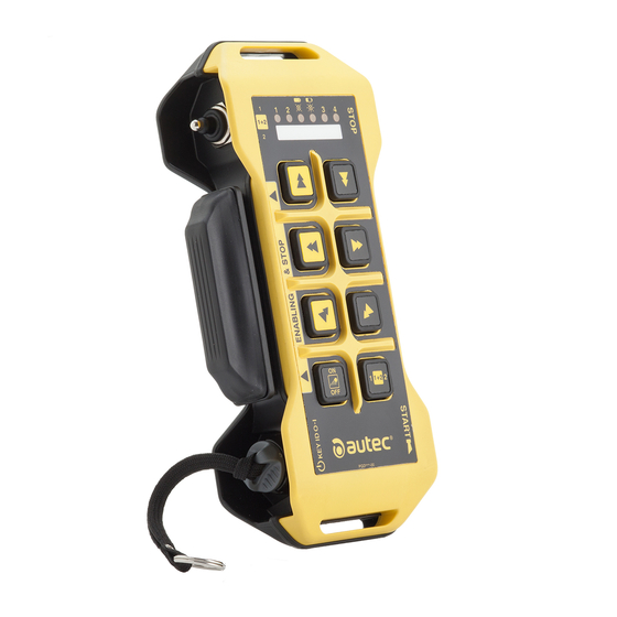
Page 2: Description
Description description Command pushbuttons Power keyswitch (if present) FUNCTION pushbutton Battery START pushbutton Actuator (selector, pushbutton) (if present) Technical data plate STOP pushbutton Radio remote control identification plate Transmitting unit identification plate DIP switches Battery housing Connector for "ID internal tx memory" LILK6E00-01 AUTEC - Air series... -
Page 3: Technical Data
A technical data sheet must always be kept toghether with this manual (always keep a copy of the technical data sheet when it is used for administrative purposes). The wiring of the receiving unit outputs must always reflect the wiring indicated in the technical data sheet. AUTEC - Air series LILK6E00-01... -
Page 4: Plates
Manufacturing year, bar transmitting unit code and transmitting Battery housing. identification plate unit identification number (TU ID). MODEL, TYPE and main transmitting unit technical data plate Battery housing. technical data, marking and possible radio remote control marks. LILK6E00-01 AUTEC - Air series... -
Page 5: Light Signals
... is steady on for 2s. The transmitting unit does not work correctly. … blinks slowly (one blink per The battery has less than 1h run time. second)..blinks fast. The battery has a 10min run time. AUTEC - Air series LILK6E00-01... - Page 6 The green Led [B] blinks and the red Led [A] is steady during start The UNPAIR procedure has been performed. See paragraph 6.3 to check the meaning of LEDs for Data Feedback function [C]. LILK6E00-01 AUTEC - Air series...
-
Page 7: General Operating Instructions
1. Insert a charged battery in the transmitting unit (see paragraph 7.1.1) 2. insert the power keyswitch in the transmitting unit (see paragraph 7.3.3) 3. press the START pushbutton until the green LED blinks slowly. AUTEC - Air series LILK6E00-01... - Page 8 PIN 3 shall not be included in the start up procedure if it coincides with the START command. 3. press the START pushbutton until the green LED blinks slowly. Note: default PIN CODE set by AUTEC is: - PIN 1=START pushbutton - PIN 2=FUNCTION pushbutton - PIN 3=START pushbutton.
-
Page 9: Command Activation
Press the START pushbutton to start the radio remote control. Transmitting unit automatic switch off The transmitting unit automatically switches off when: - the battery is flat (see paragraph 6.5.1) - the radio remote control is not used for a certain time (see paragraph 6.5.2) Press the START pushbutton to start the radio remote control. AUTEC - Air series LILK6E00-01... -
Page 10: Switching Off The Transmitting Unit
- when the STOP pushbutton is pressed. Operation Battery The Air series' transmitting units can only be powered by Autec rechargeable batteries. see the battery charger manual enclosed in the packaging with the battery charger for any warnings and instructions regarding the batteries. -
Page 11: Id Internal Tx Memory
2. rotate the power keyswitch clockwise. 7.3.4 power keyswitch removal Perform the following operations to remove the power keyswitch: 3. rotate the power keyswitch anticlockwise 4. pull the power keyswitch to remove it from the corresponding housing. AUTEC - Air series LILK6E00-01... - Page 12 If the PIN code is correct, the green LED turns steady on and the transmitting units switches off: this indicates that the address has been stored in the "BACK-UP UNIT". It is now possible to start the radio remote control and control the machine with the "BACK-UP UNIT" transmitting unit. LILK6E00-01 AUTEC - Air series...
-
Page 13: Start Pushbutton
To start working again after the STOP pushbutton has been pressed, do the following: - make sure that the working and usage conditions are safe - pull or turn the STOP pushbutton in the arrow direction to unlock it - start up the radio remote control. AUTEC - Air series LILK6E00-01... -
Page 14: Malfunction Signalled By The Transmitting Unit
The green and red Leds You're using a "BACK- are steady on. UP UNIT" with the "Key ID 0-1" or "ID internal Store the address in the "BACK-UP tx memory" of the UNIT" (see paragraph 7.3.5). transmitting unit that has been replaced. LILK6E00-01 AUTEC - Air series... - Page 15 The green Led blinks UNPAIR submenu and and the red Led is given in the document Contact the support service. steady on during start "Menu of Transmitting Unit (MTU)" has been carried out. AUTEC - Air series LILK6E00-01...
Need help?
Do you have a question about the Air LK6 and is the answer not in the manual?
Questions and answers