Table of Contents
Advertisement
Available languages
Available languages
Quick Links
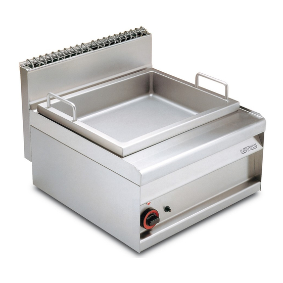
BRASIERA A GAS PER
USO PROFESSIONALE
GASBETRIEBENE BRATPFANNE
FÜR GROSSKÜCHEN
SAUTEUSE A GAZ
USAGE PROFESSIONNEL
GAS BRAT PAN
FOR PROFESSIONAL USE
GUISANDERA A GAS
PARA USO PROFESIONAL
ITALIA
= CATEGORIA II 2H3+
DEUTSCHLAND = KATEGORIE II 2ELL3B/P
ÖSTERREICH
= KATEGORIE II 2H3B/P
SCHWEIZ
= KATEGORIE II 2H3+
FRANCE
= CATEGORIE II 2E+3+
IT
DE
FR
GB
BR - 6G
BELGIQUE
= CATEGORIE I 2E+
LUXEMBOURG = CATEGORIE I 2E
NEDERLAND
= CATEGORIE I 2L
SUOMI
= KATEGORIA II 2H3B/P
II 2H3B/P
NORGE
= KATEGORI I 3B/P
DANMARK
= KATEGORI II 2H3B/P
Guida all'installazione e istru-
CH
zioni per l'uso
Installations und Gebrauchs-
AT
CH
anweisungen
Notice pour l'installation et
BE
LU
mode d'emploi
Instructions for installation and
IE
use
Guia para la intalación e
ES
instrucciones de uso
Mod.
1
ENGLAND
= CATEGORY II 2H3+
IRELAND
= CATEGORY II 2H3+
SVERIGE
= KATEGORI II 2H3B/P
ESPAÑA
= CATEGORIA II 2H3+
PORTUGAL
= CATEGORIA II 2H3+
ELLAS
= KATHGORIA I 3+
NO.DOC. BR-6G
EDIZIONE 03.02
Advertisement
Chapters
Table of Contents

Related Manuals for Lotus cooker BR-6G


Summary of Contents for Lotus cooker BR-6G
- Page 1 = KATEGORIA II 2H3B/P ESPAÑA = CATEGORIA II 2H3+ II 2H3B/P NORGE = KATEGORI I 3B/P PORTUGAL = CATEGORIA II 2H3+ FRANCE = CATEGORIE II 2E+3+ DANMARK = KATEGORI II 2H3B/P ELLAS = KATHGORIA I 3+ NO.DOC. BR-6G EDIZIONE 03.02...
- Page 2 BR - 62G Attacco Gas Targhetta caratteristiche Typenschild Gasanschluß Raccord du gaz Plaquette signalétique Gas connection Characteristics plate Placa de características Entrada del gas...
- Page 3 FIG.A Minimo Spento Massimo Pilota Min. Max. Zündflamme Mini. Maxi. Veilleuse Eteint Min. Max. Pilot Mín. Máx. Piloto Apagado...
- Page 4 Pag. Seite Page Page Pág.
-
Page 5: Table Of Contents
INDICE Dichiarazione di conformità -------------------------------------------------------------------------- 6 Installazione --------------------------------------------------------------------------------------------- 6 Verifica della corretta ventilazione ------------------------------------------------------------------ 6 Tubo per il collegamento del gas ------------------------------------------------------------------- 7 Controllo della potenza termica --------------------------------------------------------------------- 7 Allacciamento per il gas liquido G30/G31 ------------------------------------------------------- 7 Allacciamento con gas metano H G20 ------------------------------------------------------------ 7 Controllo dell'aria primaria bruciatori principali ------------------------------------------------- 7 Tabella dati tecnici ------------------------------------------------------------------------------------- 7 Disposizioni per la trasformazione ed installazione per altri tipi di gas ---------------------- 7... -
Page 6: Dichiarazione Di Conformità
DICHIARAZIONE DI CONFORMITA’ Il costruttore dichiara che gli apparecchi sono conformi alle prescrizioni della direttiva CEE 90/396. L’ installazione dovrà essere effettuata in osservanza delle norme vigenti soprattutto in merito all’ aerazione dei locali e al sistema di evacuazione dei gas di scarico. N.B.: Il costruttore declina ogni responsabilità... -
Page 7: Tubo Per Il Collegamento Del Gas
TUBO PER IL COLLEGAMENTO DEL GAS L’ allacciamento del gas é da effettuarsi con tubazioni in acciaio oppure in rame o diversamente, con tubazioni flessibili in acciaio, in conformità alla norma nazionale se esistente. Ogni apparecchio deve essere dotato di un rubinetto d’... -
Page 8: Regolazione Del Minimo
SOSTITUZIONE DELL'UGELLO DEL BRUCIATORE PRINCIPALE Fig.A • Togliere le viti anteriori di fissaggio del cruscotto (vedere figura A pos. 20), togliere il cavo di accensione dal piezoelettrico • Con una chiave adatta, svitare l'ugello (22) e sostituirlo con quello adeguato (vedere tabella "Dati tecnici"). SOSTITUZIONE DELL'UGELLO DEL BRUCIATORE PILOTA Fig.A La fiamma del bruciatore pilo ta ha l'aria fissa. -
Page 9: Accensione Del Bruciatore Principale
Ruotando la manopola ulteriormente nella posizione (min.), si fa funzionare l'apparecchio alla minima potenza. Spegnimento del bruciatore principale Fig.A Ruotare la manopola in posizione ; rimane accesa sola la fiamma del bruciatore pilota. Spegnimento dell'apparecchio Fig.A Ruotare la manopola in posizione "0". Questo comando blocca l'alimentazione del gas sia al bruciatore principale sia al bruciatore pilota. -
Page 10: Come Comportarsi In Caso Di Guasto
COME COMPORTARSI IN CASO DI GUASTO Chiudere il rubinetto dell’ allacciamento del gas e avvertire il servizio d’ assistenza. PROCENDIMENTO DA SEGUIRE IN CASO DI LUNGA INTERRUZIONE DEL FUN- ZIONAMENTO Chiudere il rubinetto del gas, pulire l’ impianto come sopra specificato. - Page 11 IT AT INHALTSANGABE Konformitätserklärung -------------------------------------------------------------------------------- 12 Installation ---------------------------------------------------------------------------------------------- 12 Belüftungskontrolle ------------------------------------------------------------------------------------ 12 Gasanschlußleitung ----------------------------------------------------------------------------------- 13 Überprüfung der Wärmeleistung ------------------------------------------------------------------- 13 Anschluß für Flüssiggas G30/G31 ---------------------------------------------------------------- 13 Anschluß für Erdgas H G20 ------------------------------------------------------------------------- 13 Anschluß für Erdgas L G25 -------------------------------------------------------------------------- 13 Kontrolle Primärluft der Hauptbrenner ------------------------------------------------------------- 13 Tabelle technische Daten ----------------------------------------------------------------------------- 13 Anleitungen zur Umstellung und Installation für andere Gasarten ---------------------------- 13...
-
Page 12: Konformitätserklärung
IT AT KONFORMITÄTSERKLÄRUNG Der Hersteller erklärt, daß die Geräte der EG-Richtlinie 90/396 entsprechen. Die Geräteinstallation muß entsprechend den einschlägigen Vorschriften, vor allem bezüglich der Belüftung der Aufstellungsräumlichkeiten und bezüglich der Abgasführung, ausgeführt werden. BEACHTE: Der Hersteller lehnt jegliche Haftung für direkte oder indirekte Schäden ab, die auf eine falsche Installation, Abänderungen, ungenügende Wartung, fehlerhafte Benutzung sowie alle anderen in unseren Verkaufsbedingungen aufgezählten Fälle, zurückzuführen sind. -
Page 13: Gasanschlußleitung
IT AT Die Geräte müssen in geeigneter Weise unter Beachtung der einschlägigen Sicherheitsbestimmungen aufgestellt werden. Mit Hilfe der Gerätefüsse kann das Gerät in der Höhe verstellt werden und es ist möglich eventuelle Höhenunterschiede zu den nebenstehenden Möbeln auszugleichen. GASANSCHLUSSLEITUNGEN Der Gasanschluß muß mit Stahl-oder Kupferrohrleitungen oder anderenfalls mit biegsamen Stahl-Rohren entsprechend den einschlägigen, nationalen Normen durchgeführt werden. -
Page 14: Tabelle Technische Daten
IT AT KONTROLLE PRIMÄRLUFT DER HAUPTBRENNER Alle Brenner sind mit speziellen Einspritzern versehen, die keine Regelung der Primärluft erfordern. Tabelle Technische Daten für DEUTSCHLAND 12.8 kWh/KG 9.45 kWh/m st. 8,12 kWh/m G30/G31 Mod. BR - 6G FLÜSSIGGAS ERDGAS H ERDGAS L Brenner 6,9 kW Max. -
Page 15: Betriebskontrolle
IT AT Wichtig! Nach der Umstellung auf eine andere Gasart, sind die technischen Eigenschaften des Typenschilds zu ändern, indem die neue Gasart angegeben wird, auf die das Gerät umgestellt wurde. BETRIEBSKONTROLLE • Das Gerät enthält die nötigen Gebrauchsanweisungen. • Die Geräte sind auf Gasleckstellen zu überprüfen. •... -
Page 16: Ausschalten Des Gerätes
IT AT ANLEITUNGEN ZUR ABGASLEITUNG Geräte des Typs “ A” (siehe Typenschild) Die Abgasleitung für Geräte des Typs “ A” muß über eigene Dunstabzughauben oder ähnliche Vorrichtungen geführt werden, die an einen betriebssicheren Kamin oder direkt ins Freie geschlossen werden. ( Natürliche Abgasleitung ) Abb. 1 Anderenfalls ist der Gebrauch eines direkt ins Freie führenden Luftabsaugers genehmigt, ( Erzwungene Abgasleitung ) Abb. - Page 17 SOMMAIRE Déclaration de conformité -------------------------------------------------------------------------- 18 Installation --------------------------------------------------------------------------------------------- 18 Vérifier si la ventilation est correcte --------------------------------------------------------------- 18 Tuyau de raccordement du gaz -------------------------------------------------------------------- 19 Contrôle de la puissance thermique -------------------------------------------------------------- 19 Raccordement gaz liquide G30/G31 ------------------------------------------------------------- 19 Raccordement gaz méthane H G20 -------------------------------------------------------------- 19 Raccordement gaz méthane L G25 --------------------------------------------------------------- 19 Contrôle de l’...
-
Page 18: Déclaration De Conformité
DECLARATION DE CONFORMITE Le fabricant déclare que les appareils sont conformes aux prescriptions de la directive CEE 90/396. L’ installation devra être effectuée conformément aux normes en vigueur, en particulier pour l’ aération des locaux et pour le système d’ évacuation des gaz brûlés. -
Page 19: Tuyau De Raccordement Du Gaz
L’ installation, la transformation et la réparation des appareils pour grandes cuisines de même que le prélèvement de l’ appareil en cas de panne et l’ alimentation en gaz ne peuvent être effectués que si un contrat d’ entretien a été stipulé avec un bureau de vente autorisé... -
Page 20: Contrôle De L' Air Primaire Brûleurs Principaux
CONTROLE DE L’ AIR PRIMAIRE BRULEURS PRINCIPAUX Tous les brûleurs sont pourvus d’ injecteurs spéciaux ne nécessitant pas une régulation de l’ air primaire. Tableau données techniques pour la FRANCE et la BELGIQUE 12.8 kWh/KG 12.8 kWh/KG 9.45 kWh/m st. 8,12 kWh/m Mod. -
Page 21: Contrôle Du Fonctionnement
Important! (pas nécessaire pour la Belgique) Après avoir effectué l’ adaptation à un autre type de gaz, il faut mettre à jour la plaquette signalétique en indiquant le type de gaz avec lequel l’ appareil a été transformé. CONTROLE DU FONCTIONNEMENT •... -
Page 22: Instructions Pour L' Évacuation Des Gaz Brûlés
INSTRUCTIONS POUR L’ EVACUATION DES GAZ BRULES Appareils du type “ A” (Voir plaquette signalétique) Les appareils du type “ A” doivent évacuer les produits de la combustion à travers des hottes ou des dispositifs similaires qui pourront être raccordés à une cheminée de sécurité efficace ou bien directement à l’ extérieur. (Evacuation naturelle) Fig. 1 Si vous ne disposez pas de telle installation, il est admis d’... - Page 23 INDEX Conformity declaration --------------------------------------------------------------------------------24 Installation -----------------------------------------------------------------------------------------------24 Checking for adequate ventilation ------------------------------------------------------------------24 Gas connection pipe ----------------------------------------------------------------------------------25 Checking the thermal power control ----------------------------------------------------------------25 Connection for liquid gas G30/31 ------------------------------------------------------------------25 Connection with natural gas (methane) H G20 ---------------------------------------------------25 Checking the primary air of the main burners -----------------------------------------------------25 Specification table -------------------------------------------------------------------------------------25 Provisions for transformation and installation for other types of gas --------------------------25 Minimum adjustment ----------------------------------------------------------------------------------26...
-
Page 24: Conformity Declaration
CONFORMITY DECLARATION The manufacturer declares that the appliances are in accordance with the EEC 90/396 directive provisions. The installation must be carried out in observance of the standards in force above all regarding the airing of the rooms and the evacuation system of the exhaust gases. N.B. -
Page 25: Gas Connection Pipe
GAS CONNECTION PIPE The gas must be connected using steel or copper pipes, or with flexible steel pipes, in accordance with the laws of the country where the appliance is installed. Each appliance must be furnished with an easy-closure cutoff cock for the gas. After installation, a check must be made for possible gas leaks from the fittings;... -
Page 26: Minimum Adjustment
MINIMUM ADJUSTMENT Fig.A After tranforming the appliance for another type of gas, the minimum flame must be adjusted by turning screw (3) to the right or left until the minimum thermal power measures 3,1 kW. SUBSTITUTION OF THE MAIN BURNER NOZZLES Fig.A •... -
Page 27: Ignition Of The Main Burner And Temperature Regulation
Ignition of the main burner and temperature regulation Fig.A After releasing the button (A), rotate it to position (max.) to ignite the main burner. By rotating the knob further to the position (min.), the appliance will operate at the minimum level Turning off the main burner Fig.A Rotate the knob to the... -
Page 28: Cleaning And Maintenance
CLEANING AND MAINTENANCE Daily cleaning of the appliance after use ensures that it works perfectly and lasts longer. The steel parts should be cleaned with a damp cloth and detergent only. The surface of the top grill must be coated with a thin layer of combustible oil if not used for a lengthy period. - Page 29 LEGENDA Declaración de conformidad ------------------------------------------------------------------------- 30 Instalación ----------------------------------------------------------------------------------------------- 30 Comprobación de una correcta ventilación ------------------------------------------------------- 30 Tubo para la conexión del gas ---------------------------------------------------------------------- 31 Control de la potencia calorífica -------------------------------------------------------------------- 31 Conexión para el gas líquido G30/G31 ---------------------------------------------------------- 31 Conexión con el gas metano H G20 --------------------------------------------------------------- 31 Control del aire primario de los quemadores principales -------------------------------------- 31 Tabla de datos técnicos ------------------------------------------------------------------------------- 31 Disposición para la transformación e instalación de otros tipos de gas --------------------- 31...
-
Page 30: Declaración De Conformidad
DECLARACION DE CONFORMIDAD El Fabricante declara que los aparatos están conformes con lo dispuesto por la norma IEC 90/396. La instalación debe realizarse cumpliendo con las normas vigentes, en especial por lo que concierne a la ventilación de los cuartos y al sistema de evacuación de los gases quemados. -
Page 31: Tubo Para La Conexión Del Gas
TUBO PARA LA CONEXION DEL GAS La conexión del gas se efectúa con tuberías de acero o bien de cobre o si no tuberías flexibles de acero con referencia, donde existan, a las normas nacionales. Cada aparato debe tener un grifo de paso del gas con un cierre fácil. Después de la instalación es necesario efectuar un control de las pérdidas posibles de gas en los racores;... -
Page 32: Regulación Del Mínimo
REGULACION DEL MINIMO Fig. A Después de haber realizado el cambio para otro tipo de gas, es necesario regular el mínimo girando el tornillo (3) a la derecha o a la izquierda hasta que la potencia calorífica mínima alcance los 3,1 kW. SUSTITUCION DEL INYECTOR DEL QUEMADOR PRINCIPAL Fig.A •... -
Page 33: Encendido Del Quemador Principal
ENCENDIDO DEL QUEMADOR PRINCIPAL Encendido del quemador piloto Fig.A Girar el mando (A) desde la pos. “ 0” hasta . Mantener apretado el mando (A), luego actuar repetidas veces sobre el botón piezoeléctrico (18). La llama se enciende automáticamente y está visible a través de la mirilla del panel anterior. Después del encendido mantener apretado el mando (A) durante unos 5-10 segundos más, para que el termopar pueda calentarse, luego soltarlo. -
Page 34: Observaciones Y Recomendaciones
OBSERVACIONES Y RECOMENDACIONES Usar el aparato sólo bajo vigilancia. CUIDADO: no utilizar el aparato con la cuba vacía. LIMPIEZA Y MANTENIMIENTO Después de apagar el aparato, su limpieza diaria garantizas su perfecto funcionamiento y su duración a lo largo del tiempo. Las partes en acero se limpian con un estropajo mojado con detergente, sin frotar;...
Need help?
Do you have a question about the BR-6G and is the answer not in the manual?
Questions and answers