Table of Contents
Advertisement
Available languages
Available languages
Quick Links
Istruzioni
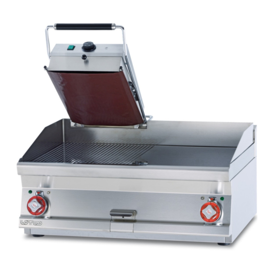
PIASTRA SUPERIORE PER FRY
IT
CH
per l'installazione e l'uso
TOP
Aufstellungs
DE
AT
CH
UPPER BRATPLATTE
und Bedienungsanleitung
Instructions
FR
BE
TOP HAUT RFY PLAQUE
Pour l'installation et l'emploi
Instructions
GB
IE
UPPER PLATE FRY TOP
for installation and use
Instrucciones para la instalación
ES
PLACA SUPERIOR PARILLA
y el uso
Mod.
RSFT-63EM
RSFT-73EM
563020801.doc
LIBR.ISTR.RSFT
1
Advertisement
Table of Contents

Related Manuals for Lotus cooker RSFT-63EM


Summary of Contents for Lotus cooker RSFT-63EM
- Page 1 Aufstellungs UPPER BRATPLATTE und Bedienungsanleitung Instructions TOP HAUT RFY PLAQUE Pour l’installation et l’emploi Instructions UPPER PLATE FRY TOP for installation and use Instrucciones para la instalación PLACA SUPERIOR PARILLA y el uso Mod. RSFT-63EM RSFT-73EM 563020801.doc LIBR.ISTR.RSFT...
- Page 2 FIG. A 562030801M00P00 RSFT-63EM RSFT-73EM 699,5 804,5 Tagliare il paraspruzzi Schneiden Sie das Kurbelgehäuse Couper le carter Cut the crankcase Cortar el cárter...
- Page 3 SCHEMA ELETTRICO – SCHALTPLAN – SCHEMA ELECTRIQUE WIRING DIAGRAM – ESQUEMA ELECTRICO 230Vac 50/60 Hz Morsettiera arrivo linea Klemmleiste linie Plaque à borne arr. Ligne Terminal board Conexión eléctrica Interruttore luminoso Beleuchtete Schalter Interrupteur lumineux Illuminated switch Interruptor iluminado Termostato Thermostat Thermostat Thermostat...
- Page 4 ISTRUZIONI PER MONTAGGIO MONTAGEANLEITUNG INSTRUCTIONS POUR LE MONTAGE ASSEMBLY INSTRUCTIONS Fig. 1) Mettere in posizione l’apparecchio inserendolo sul distanziale posteriore del fry-top. Stellen Sie das Gerät und stecken Sie das in dem hinteren Platz der Griddleplatte Réglez le dispositif en le insérant dans le dos de la plaque Set the device by inserting it into the rear spacer of the griddle.
- Page 5 Fig. 2-3) Praticare 4 fori Ø3,5mm nelle posizioni sotto indicate per viti autofilettanti. Bohren Sie 4 Löcher Ø 3,5 mm in den unten aufgeführten Positionen für Blechschrauben. Pratiquez 4 trous Ø 3,5 mm aux endroits ci-dessous pour les vis autotaraudeuses. Drill 4 holes Ø3, 5mm in the below listed positions for self-tapping screws Fig.
- Page 6 Fig.4-5) MOLLA TIPO A, SPRING TYP A, TYPE DE SPRING A, SPRING TYPE A Tendere le molle di fissaggio in modo che il peso della piastra sia bilanciato sia in apertura che in chiusura (vedi freccia gialla) Foro consigliato nr. 12 partendo dal basso Ziehen Sie die Befestigungsfedern, so dass das Gewicht der Platte ausgeglichen ist sowohl beim Öffnen und Schließen (siehe gelber Pfeil) Empfohlene Loch Nr.
- Page 7 Fig.4-5) MOLLA TIPO B, SPRING TYP B, TYPE DE SPRING B, SPRING TYPE B, TIPO DE MUELLE B...
- Page 8 Tendere le molle di fissaggio in modo che il peso della piastra sia bilanciato sia in apertura che in chiusura (vedi freccia gialla) Fori consigliati nr. 4 e 7 partendo dall’alto Ziehen Sie die Befestigungsfedern, so dass das Gewicht der Platte ausgeglichen ist sowohl beim Öffnen und Schließen (siehe gelber Pfeil) Empfohlene Loch Nr.
- Page 9 Fig.6) Chiudere il pannello posteriore Schließen Sie die Rückwand Fermez le panneau arrière Close the back panel Fig.6...
- Page 10 Pag. Seite Page Page Pàg.
- Page 11 INDICE DICHIARAZIONE DI CONFORMITA’ ........................12 DATI TECNICI ................................12 IMBALLAGGIO E CONTROLLO DELL’APPARECCHIO ................... 12 Avviso importante ..............................12 ISTRUZIONI TECNICHE PER L’INSTALLAZIONE ..................... 12 Importante: ................................12 POSIZIONAMENTO ..............................12 PRESCRIZIONI INSTALLAZIONE PER PREVENZIONE INCENDI ..............13 COLLEGAMENTO ALLA RETE ELETTRICA ....................... 13 ISTRUZIONI PER L’USO ............................
-
Page 12: Dichiarazione Di Conformita
DATI TECNICI CAVO DIMENSIONI ASSORBIMENTO POTENZA MODELLI ALIMENTAZIONE ALIMENTAZIONE MASSIMO A MASSIMA kW (Al silicone) RSFT-63EM 320x607x415h 230Vac 50/60 Hz 12,6 3x1,5 mm² RSFT-73EM 320x621x417h 230Vac 50/60 Hz 12,6 3x1,5 mm² IMBALLAGGIO E CONTROLLO DELL’APPARECCHIO L’apparecchio esce dai nostri magazzini adeguatamente imballato e con le marcature, targhette ed istruzioni adeguate. -
Page 13: Collegamento Alla Rete Elettrica
PRESCRIZIONI INSTALLAZIONE PER PREVENZIONE INCENDI L’apparecchio può essere usato solo da persone adulte L'interruttore generale o la presa devono essere nelle vicinanze dell'apparecchio e facilmente accessibili. Si consiglia di porre l'apparecchio sotto una cappa aspirante, in modo che l'evacuazione dei vapori avvenga in modo rapido. -
Page 14: Pulizia E Manutenzione
ISTRUZIONI PER L’USO Disimballare il dispositivo e verificare i danni di trasporto. Collegare il dispositivo al fry top secondo l'immagine e le istruzioni del presente manuale, usando i distanziatori e le viti. Dopo questo, installare le molle. È necessario osservare la distanza minima di 10 cm dal resto dei punti, ed impedire il contatto del dispositivo con materiali combustibili. - Page 15 Eventuali danni derivanti dal trasporto, da cattiva installazione o manutenzione non saranno considerati argomenti validi di contestazione ai fini della garanzia. L’intervento di ordinaria manutenzione o per cause derivanti da errata installazione non è coperto da garanzia. La garanzia è valida soltanto nei confronti dell’acquirente originario.
- Page 16 TABLE DES MATIÈRES DÉCLARATION DE CONFORMITÉ ......................... 17 DONNÉES TECHNIQUES ............................17 VERIFICATION DE L´EMBALLAGE ........................17 Recommandations importantes ..........................17 INSTALATION ET REGLAGE ........................... 17 Attention ................................17 LOCATION ..................................17 MISE EN PLACE DE LA PRÉVENTION DES INCENDIES ................... 18 BRANCHEMENT ELECTRIQUE ..........................
-
Page 17: Déclaration De Conformité
CÂBLE DIMENSIONS ABSORPTION PUISSANCE MODÈLES ALIMENTATION D'ALIMENTATION (cm) MAXIMUM A MAXIMUM kW (au silicone) RSFT-63EM 320x607x415h 230Vac 50/60 Hz 12,6 3x1,5 mm² RSFT-73EM 320x621x417h 230Vac 50/60 Hz 12,6 3x1,5 mm² VERIFICATION DE L´EMBALLAGE L‘appareil quitte les magasins du fabricant dans un emballage en bonne et due forme. Sur l‘emballage sont apposés les étiquettes et les symboles nécessaires à... -
Page 18: Branchement Electrique
contact avec des matières inflammables. Dans ce cas, il faut prévoir les arrangements nécessaires pour assurer l’isolation thermique des parties inflammables. MISE EN PLACE DE LA PRÉVENTION DES INCENDIES Le dispositif peut être utilisé que par des adultes L'interrupteur général ou la prise doit se trouver à proximité de l'appareil et être facile d'accès. Il est recommandé... -
Page 19: Nettoyage Et Entretien
Allumer l’appareil a l’aide de l’interrupteur principal (A). Tourner le dispositif de commande (B) jusqu’à chèque la puissance souhaitée soit réglée. Le témoin lumineux vert (A) indique : –si l’appareil est en marche. Le témoin orange (C) signale le fonctionnement du corps de chauffe et lorsqu’il s’éteint, l´appareil est chauffé... - Page 20 INDEX DECLARATION OF COMPLIANCE ......................... 21 TECHNICAL DATA ..............................21 PACKING AND DEVICE CHECK ..........................21 Important notice ..............................21 TECHNICAL INSTRUCTIONS FOR INSTALATION AND REGULATION ............21 Important: ................................21 PLACEMENT ................................. 21 SAFETY MEASURES FROM THE STANDPOINT OF THE FIRE PROTECTION ..........22 CONNECTION OF THE ELECTRIC CABLE TO THE ELECTRICITY ..............
-
Page 21: Declaration Of Compliance
ABSORPTION A POWER kW CABLE (Silicone) 320x607x415h 230Vac 50/60 Hz 12,6 3x1,5 mm² RSFT-63EM RSFT-73EM 320x621x417h 230Vac 50/60 Hz 12,6 3x1,5 mm² PACKING AND DEVICE CHECK The device leaves our stocks properly packed with appropriate symbols and labels. There are also appropriate instructions for use. - Page 22 SAFETY MEASURES FROM THE STANDPOINT OF THE FIRE PROTECTION Only adults can operate the device The main switch or the socket must be near the appliance and easily accessible. It is advisable to place the appliance under an extractor hood so that steam is extracted rapidly. If the appliance is placed near walls, dividing panels, kitchen furniture, decorative finishing, etc.
-
Page 23: Cleaning And Maintenance
INSTRUCTION FOR USE Unpack the device and check for transport damage. Attach the device to the fry top according to the picture either using the standoffs or standoffs and screws. After this, fit the springs on the classic plate for them to hold it in raised position and at the same time not to lift it spontaneously when the device is lowered. - Page 24 INDICATION Guarantee does not cover all consumption parts succumable to common wear (rubber seals, bulbs, glass and plastic parts etc.). The guarantee does not refer to the devices which were not installed in correspondence with instructions - by qualified worker, in conformity with standards and when somebody handled incompetently the device (interventions into inner equipment) or the device was operated by non qualified staff or at variance with instructions for use.
Need help?
Do you have a question about the RSFT-63EM and is the answer not in the manual?
Questions and answers