Advertisement
Quick Links
Advertisement

Related Manuals for SCREENLINE SL27M


Summary of Contents for SCREENLINE SL27M
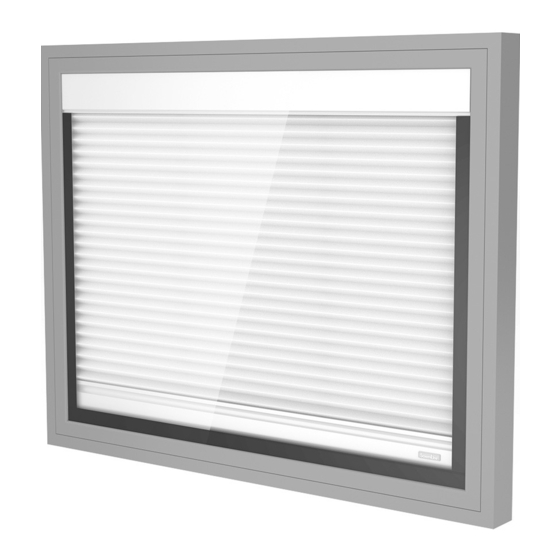
- Page 1 PLEATED BLIND SL27M plissé ® ScreenLine double-glazed unit 27 mm...
- Page 2 The ScreenLine ® SL27M pleated blind with motor inside the head rail for incorporation within a double-glazed unit, is manufactured in accordance with high technical specifi- cation and production standards. The blind raising / lowering functions are achieved by way of an encoder motor that permits a constant speed resulting in a guaranteed synchronized function for multiple blinds.
-
Page 3: Technical Features
technical features A mechanical end-stop incorporated within the head-rail, ensures a safety stop of the blind in the lower position. The entire kit is contained within the spacer bar frame thereby ensuring the hermetic seal of the unit. Height 300 ~ 2.500 mm Width 420 (320 with double head rail system) ~ 2.200 mm Maximum area... - Page 4 PLEATED BLIND SL27M plissé ® Performance characteristic of the Verosol fabric Pleated Verosol ® Solar Light Solar Solar Light Fabric reflection % reflection % absorbing % transmission % transmission % Performance characteristic of the Vanity fabric Pleated Vanity Light reflection %...
- Page 5 ScreenLine...
-
Page 6: Technical Drawings
SL1280 27x8 mm Drum support SL1914 Extruded “C” shaped spacer bar SL1775 End stop cap SL1752 Bottom rail end cap SL1217 ScreenLine plastic label SL1047 Cord eyelet SL1197 SL1045 Bottom rail cover Polyester cord 1.4 mm SL1048 SL1013 SL1667 Extruded “U” shaped spacer bar... - Page 7 Glass W 20 mm PLEAT EXTRUDED OPEN SPACER BAR EXTRUDED “U” SPACER BAR EXTRUDED “C” SPACER BAR Glass W 20 mm PLEAT EXTRUDED OPEN SPACER BAR EXTRUDED “U” SPACER BAR EXTRUDED “C” SPACER BAR ScreenLine...
- Page 8 SL27M plissé feasibility Width cm 32 37 42 50 60 70 80 90 100 110 120 130 140 150 160 170 180 190 200 210 220 Only double head rail Standard Not feasible (or double head rail)
- Page 9 ScreenLine ® kit components On receipt of the goods, check the integrity of the package and confirm that the components are as detailed on the Purchase Order. The kit comprises: • pleated blind with corner keys assembled to the upper spacer •...
- Page 10 assembly instructions Line assembly Pass the first glass through the washer either on its base or on its height. Position the assembled kit on the first glass, ensu- ring that the head rail is on the top or on one side. During this operation, it is recommended great care is taken with the inte- gral blind, in order to avoid any dirt or damage to the fabric.
- Page 11 assembly instructions Second sealing Raise the blind completely apply the final seal in accordance with EN1279-2 regulation. The secondary sealant should be applied ensuring that the area around the silicone tubes is completely filled either by the automatic sealing machine or by hand. The silicon tubes should remain straight and not damaged.
- Page 12 Transport and Storage For transport and storage procedures please check the recom- mendations contained in the relevant part of the ScreenLine ® removal of the silicon tubes Technical Catalogue.
- Page 13 SL1807 Control unit This unit is used to control the polarity inversion necessary for the correct function of the motor, which would not be realised when using normal switches. Each control unit can control one blind, or can simultaneously control a group of up to four blinds, depending on the requi- rements of the system.
- Page 14 Power supply This power supply unit has been specially developed for the SL27M motor. It comprises two external brackets for wall fixing and two internal terminal blocks – one for the mains power supply connection and the other for the 24V dc output.
- Page 15 Function of the blind The system SL27M pleated must be connected to a power supply sufficient to ensure a con- stant 24V dc supply to all the connected motors. The electronic card, contained inside the blind, controls the several functions, one of which controls the stop position corresponding to the end stop of the top and bottom positions.
- Page 16 diagrams electric • Remote radio control should also be used in conjunction with a dedicated “control unit”. The following selection of wiring diagrams indicates the wide variety of possible combina- tions. To raise/lower the blind, press the Up or Down switch until the speed increases. Once the fast speed is reached the button can be released and the blind will continue to move, reaching the end stop where it automatically slows.
- Page 17 ScreenLine...
- Page 18 ScreenLine...
- Page 19 ScreenLine...
- Page 20 ScreenLine...
- Page 21 ScreenLine...
- Page 22 ® Pellini general sale terms and conditions 1. OVERALL The general sale terms and conditions specified below (“General Sale Terms and Conditions”), are an integrated part of the order and/or order confirmation regarding the products and/or services (“Order” and “Order Confirmation”) submitted to and supplied by Pellini S.p.A. (“Company”). Therefore the order is accepted by the company and placed by the purchaser (“Purchaser”) in compliance with the General Terms which - unless otherwise agreed and undersigned by the Company - must be deemed to prevail over the various clauses and conditions referred to by the Purchaser.
- Page 23 PLEATED BLIND SL27M plissé 10. FORCE MAJEURE Should the Company be faced with the impossibility to carry out the delivery within the agreed terms, due to circumstances beyond its control such as, by way of illustration and not exhaustive: war, governmental restrictions, strikes or lockouts, work force demonstrations or other general or local events;...
Need help?
Do you have a question about the SL27M and is the answer not in the manual?
Questions and answers