Advertisement
Quick Links
Advertisement

Related Manuals for SCREENLINE SL20M


Summary of Contents for SCREENLINE SL20M
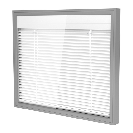
- Page 1 VENETIAN BLIND SL20M SL22M ® ScreenLine double-glazed unit 20 mm • 22 mm...
-
Page 2: Venetian Blind
The ScreenLine ® SL20M or SL22M Venetian blind with motor inside the head rail for incor- poration within a double-glazed unit, is manufactured in accordance with high technical specification and production standards. The Venetian blind operation, the slat tilting and the blind raising / lowering functions, are achieved by way of an encoder motor that per- mits a constant speed resulting in a guaranteed synchronized function for multiple blinds. -
Page 3: Technical Features
technical features the drive is transmitted through a “special” corner key; this system allows the position of the first hole in the slat to be closer to the edge, guaranteeing a better blind stability. The electric system incorporates a polarity inverter allowing the raise and lower function of all the connected blinds to be fully synchronized using only two wires. - Page 4 VENETIAN BLIND SL20M SL22M Slat Aluminium, AA 6010-T8 alloy. Dimensions: width 12,5 mm, thickness 0.2 mm. High-resistance polyester paint. Available colours: nine. The slat have a special treatment designed to eliminate possible emissions of chemical products inside the double-glazed unit, when exposed to ultraviolet and heat radiation i.e. non-fogging.
- Page 5 6,3 A. Power supply 230V AC Mains voltage input / 24V DC +/- 5% output, 2A. Protection fuse 3,15 A delayed, for up to a maximum 4 blinds. Dimensions: 110 (130 mm with fixing projections)x 85x50 mm (height) ScreenLine...
-
Page 6: Technical Drawings
SL20M technical drawings comprehensive drawing with component codes SL1148 Cord fixing ring SL1844 SL1042 Internal motor with encoder SL1145 Slat spacer 12.5 mm Sliding tube cap SL1817 SL1149 Head rail (painted) Ladder tape fixing ring SL1052 Calibrated tube SL1850 Tube support SL20-22M... - Page 7 SL1850 Tube support SL20-22M SL1819 Extruded open spacer bar 22x6,5 mm SL1856 - SL1857 End stop RH End stop LH SL1217 ScreenLine plastic label SL1627 SL1820 Bottom rail Plastic corner key weight 15 gr 22x6,5 mm SL1773 Extruded "U" shaped spacer bar...
- Page 8 Glass W 12.5 mm SLAT ScreenLine EXTRUDED “U” SPACER BAR EXTRUDED “L” SHAPED SPACER BAR Glass W 12.5 mm SLAT ScreenLine EXTRUDED “U” SPACER BAR EXTRUDED “C” SPACER BAR ScreenLine...
- Page 9 SL20M SL22M feasibility Width cm 30 35 40 45 50 60 70 80 90 100 110 120 130 140 150 160 170 180 190 200 Feasible Not feasible...
- Page 10 Assemble all the spacer bars to form the comple- te spacer frame. Ensure that the spacer projection (L-profile) for the system SL20M faces the soft coated glass where applica- ble. Ensure continuity of the butyl seal - particularly at the corner keys.
- Page 11 assembly instructions Line assembly Pass the first glass through the washer either on its base or on its height. Position the assembled kit on the first glass, ensuring that the head rail is on the top or on one side. During this operation, it is recommended great care is taken with the integral blind, in order to avoid any dirt or damage of the slats.
- Page 12 assembly instructions Second sealing Raise the blind completely and apply the final seal in accor- dance with EN1279-2 regulation. The secondary sealant should be applied ensuring that the area around the silicone tubes is completely filled either by the auto- matic sealing machine or by hand.
- Page 13 Transport and storage For transport and storage procedures please check the recom- mendations contained in the relevant part of the ScreenLine ® removal of the silicon tubes Technical Catalogue.
- Page 14 SL1807 Control unit This unit is used to control the polarity inversion necessary for the correct function of the motor, which would not be realised when using normal switches. Each control unit can control one blind, or can simultaneously control a group of up to four blinds, depending on the requi- rements of the system.
- Page 15 Power supply This power supply unit has been specially developed for the SL20M / SL22M motor. It comprises two external brackets for wall fixing and two internal terminal blocks – one for the mains power supply connection and the other for the 24V dc output.
- Page 16 Function of the blind The system SL20M – SL22M must be connected to a power supply sufficient to ensure a con- stant 24V dc supply to all the connected motors. The electronic card, contained inside the blind, controls the several functions, one of which controls the stop position corresponding to the end stop of the top and bottom positions.
- Page 17 diagrams electric • Remote radio control should also be used in conjunction with a dedicated ‘control unit’. The following selection of wiring diagrams indicates the wide variety of possible combina- tions. To tilt the slats of the blind, keep pressing the respective up or down switch till the desi- red inclination is achieved.
- Page 18 ScreenLine...
- Page 19 ScreenLine...
- Page 20 ScreenLine...
- Page 21 ScreenLine...
- Page 22 ScreenLine...
Need help?
Do you have a question about the SL20M and is the answer not in the manual?
Questions and answers