Table of Contents
Advertisement
Quick Links
MANUAL DE SERVICE
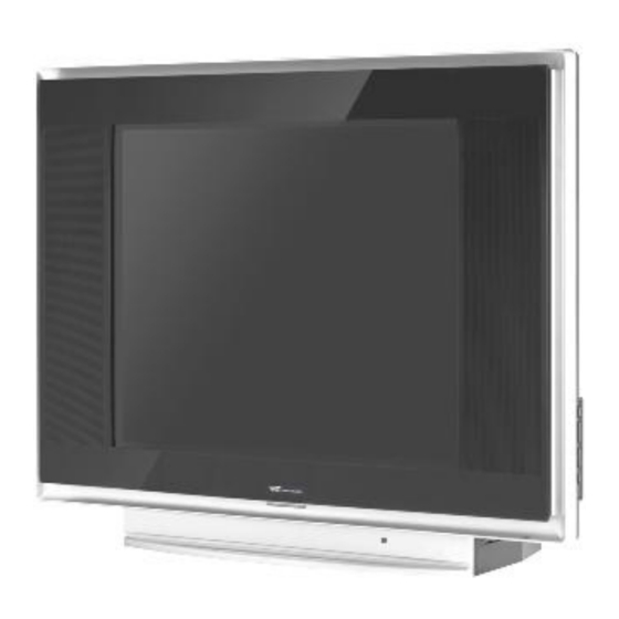
BT2909S (29M63)
CHASIS NX-56 VERSION G
BT2909S
Cod. P.T.
PNE040084
Serie DCD5
EW0
Total: 29" (74 cm)
Tamaño de pantalla
Visible: 27" (68 cm)
Tensión de alimentación
110 – 240 VCA
Consumo
Máximo: 105
(W)
Stand by: <3
Sintonizador PAL-N/M, NTSC,
Entradas
2xAV, YPbPr, S-Video
Alto: 631,0
Dimensiones
Ancho: 850,0
(en milímetros)
Prof.: 435,0
Peso neto
43 Kg
Advertisement
Table of Contents

Summary of Contents for BGH BT2909S
- Page 1 MANUAL DE SERVICE BT2909S (29M63) CHASIS NX-56 VERSION G BT2909S Cod. P.T. PNE040084 Serie DCD5 Total: 29” (74 cm) Tamaño de pantalla Visible: 27” (68 cm) Tensión de alimentación 110 – 240 VCA Consumo Máximo: 105 Stand by: <3 Sintonizador PAL-N/M, NTSC,...
- Page 2 Indice Precauciones ..................Especificaciones ..................7 Menú de service ..................11 Diagrama en bloques ................20 Funcionamiento general ............... 21 Placas de circuito impreso ............... 28 Circuitos esquemáticos ................35 Listado de componentes ................42 Hojas de datos ..................47 Vista explotada ..................
- Page 3 Notas Antes de salir del menu de service, se debe llevar el valor FACTORY HOTKEY, del menu 4, a 0. Despues de esto se debe apagar el televisor, volver a encenderlo y presionar el boton Menu para verificar que se accede al menu de usuario.
- Page 4 1、 CAUTION: Use of controls, adjustments or procedures other than those specified herein may result in hazardous radiation exposure. CA UTION: TO REDUCE THE RISK OF CAUTION ELECTRICAL SHOCK, DO NOT REMOVE COVER (OR BACK). NO USER SERVICEABLE RISK RISK OF OF ELECTRI ELECTRIC C PARTS INSIDE.
-
Page 5: Important Safety Instructions
IMPORTANT SAFETY INSTRUCTIONS CAUTION: Read all of these instructions. Save these instructions for later use. Follow all Warnings and Instructions marked on the audio equipment. 1. Read Instructions- All the safety and operating instructions should be read before the product is operated. 2. - Page 6 PROTECTION AND LOCATION OF YOUR SET Do not use this television set near water ... for example, near a bathtub, washbowl, kitchen sink, or laundry tub, in a wet basement, or near a swimming pool, etc. Never expose the set to rain or water. If the set has been exposed to rain or water, unplug the set from the wall outlet and refer servicing to qualified service personnel.
- Page 7 OPERATION OF YOUR SET 18. This television set should be operated only from the type of power source indicated on the marking label. If you are not sure of the type of power supply at your home, consult your television dealer or local power company. For television sets designed to operate from battery power, refer to the operating instructions.
- Page 8 TTE Corporation R D Center (Shen’Zhen Lab) Model NX56-LA NX56-LA Item 29185 21M63US Master Data -Version -Customer ID -Destination -Brand -BOM NO. 03-B185SAE-SC31 03-DM63SAE-SC31S -Chassis Reception -Tuning [Channels Amt.] -Tuning [Technology] -Tuning [Indication] Channel Channel -Frequency Bands Antenna AND Cable Antenna AND Cable -IF Frequency 45.7MHz...
- Page 9 TTE Corporation R D Center (Shen’Zhen Lab) Model NX56-LA NX56-LA Item 29185 21M63US -Nicam -America Stereo (MTS,BTSC,MPS) -America SAP -Korea Stereo -Thai Bilingual -Super Woofer -AVL -Sound Control [General] Volume Mute -Sound Control [Special] Treble Bass Balance Equalizer Smart Sound * modes Others -Speakers Quantity User Interface...
- Page 10 TTE Corporation R D Center (Shen’Zhen Lab) Model NX56-LA NX56-LA Item 29185 21M63US -Front Cabinet Color -Middle Cabinet Color -Rear Cabinet Color -Local Controls Front Mains Switch CH+ CH- VOL+ VOL- TV/AV Menu Auto Search -Local Controls Top CH+ CH- VOL+ VOL- TV/AV Menu Auto Search...
- Page 11 TTE Corporation R D Center (Shen’Zhen Lab) Model NX56-LA NX56-LA Item 29185 21M63US Guarantee Doc. Warning Label Approbation Label Others -Languages DFU -Indication on BACKOVER Made-in in family sheet FCC/Elect Shock Caution Label CE/Elect Shock Caution Label Warning Label Others Approbation IEC65 IEC65...
- Page 12 1.1. The way to enter P-Mode a) Method one Switch on the TV set. Press the “MENU” key on RC to show the “PICTURE” OSD menu. Move the cursor to “Contrast” item then press the “9”, “7”, “3”, “5” key continuously on RC within 3 seconds then enter P-Mode.
- Page 13 2. Flowchart of alignment procedure B+ adjustment Electrical RF AGC properties adjustment checking for chassis Parameter setup White balance Aging Adjustment of Adjustment of Adjustment focus voltage screen voltaget PAL geometry NTSC Set shopping QC checking adjustment geometry status adjustment 1) B+ Adjustment 2) RF AGC Adjustment 3) Screen &...
-
Page 14: Adjustment Description
3. Adjustment description *Notes: Alignment should be done after 3 minutes warm up of TV. 3.1 B+ Voltages 1. All relevant connectors and modules must be connected and inserted. 2. Main voltage is at 220VAC, 50Hz.(voltage range:110VAC~240VAC,50Hz) 3. Connect a voltmeter to B+ (Cathode of D808) and switch on the set. 4. - Page 15 3.2 RF AGC alignment 3.2.1 Method 1 A. Connect the detector as shown below (Picture 3.2) to collector of Q101. B. Receive a grey scale signal with 70dBμV amplitude. C. Enter P-Mode, press “6” key on RC to select “AGCT”. D.
- Page 16 3.4 White Balance Adjustment 1. Input a black and white pattern to RF input. 2. Enter P-Mode, press key “3 ” to select white balance adjustment menu. 3. Use the color analyzer to measure the black side of the screen. Adjust the value of “RC”,”GC”...
- Page 17 3.5.1 Vertical geometry adjustment 1. Input a PAL crosshatch pattern signal to RF input. 2. Enter P-Mode, press key “1” to select vertical geometry adjustment. (The OSD menu for this adjustment as below table 3.5.1. For NTSC signal, the “-50” will replace with “-60”.) 3.
- Page 18 HPARALLEL Horizontal parallelogram(HP) Adjust to right value AUTO OFFSET Automatic offset NTSC geometry See below description *Notes: 1. For NTSC signal, the “-50” will replace with “-60”. 2. For NTSC signal, only the “HCEN-60” and “HSIZE-60” items need the adjustment, the other items use the same data as PAL signal.
- Page 19 VX Compr. 16:9 mode vertical zoom Don’t adjust, use default Wide blanking start Don’t adjust, use default Wide blanking end Don’t adjust, use default GET OFFSET Get offset See below description ColdRD Cold color temperature R 64= offset value 0 63= offset value -1 65= offset value +1 Adjust to and G drive offset ColdGD...
- Page 20 X-ray detection Don’t adjust, use default Black current stabilization Don’t adjust, use default Black current loop application Don’t adjust, use default Black current measuring lines in over OSVE Don’t adjust, use default scan(for vertical zoom setting <1) Set the cathode drive level Don’t adjust, use default Don’t adjust CC-LINE...
- Page 21 Chapter II Block Diagram of NX56 July5,2008 Bridge Power B 33V Q501 220VAC Rectifier Transistor Transformer +-14V Q503 INPUT DB801- Q801 T801 Q505 DB804 2SK2996 IC801 Photo-Coupler ▽ NCP1337 IC803 Antenna R/G/B P201 V.AMP. Tuner IF AMP SAW Z2O1 IC301 TU101 Q101 Pin44-46...
-
Page 22: Brief Introduction
NX56 Chassis Signal Processing Introduction Brief introduction For different market requirements, our design it in two versions, one is for Latin America, we call the chassis as NX56-LA, the another one is for Asia Pacific Area, we call the chassis as NX56-AP. NX56-LA and NX56-AP adopt different UOC, The UOC for Latin America have CCD-Chip and BTSC function, so added AN5832SA to realize BTSC, but the UOC for Asia Pacific region does not have the two functions but... - Page 23 RF Section Tuner Tu101 receive the radio frequency signal, after inside circuit to do signal receiving, and signal amplifying. The amplified high frequency signal accompany with the high frequency oscillation voltage oscillated by set oscillator input to the mixer. The IF picture signal and sound signal formed in mixer and output from mixer, then send to picture IF processing circuit.
- Page 24 Small Signal Processing Section Small signal processing section is the IF (intermediate frequency) signal across saw filter send in the pin12 and pin13 of IC201. The VIFIN signal through built-in PLL DEMOD, sound trap, video amplifier and synchronous detector processing, get the color video broadcast signal and 2 sound IF signal.
- Page 25 (Fig3. Block Diagram of IC201.) Horizontal Scanning Section The horizontal drive signal send out from pin 56 of IC201, Q401 is horizontal driving transistor, coupled by horizontal driving transformer T402 , to control the horizontal output transistor working in switch on and off situation, get good linearly and enough amplitude of saw-tooth wave current to drive horizontal deflection yoke scanning.
- Page 26 Vertical Scanning Section Vertical scanning section adopted STV8172A vertical deflection booster, we use as differential-output driver. The vertical raw-tooth wave signal sends out from pin14/15 of IC201 VDA/VDB. The two differential signal input pin 1 and 7 of STV8172A IC301. Pin2(+14v) and Pin7(-14v) of IC301 is power supply which come from the main power transformer.
-
Page 27: Power Supply Section
Audio Power Amplifying Section Power Supply Section AC supply 220V/110v through filtering network and rectifying circuit and get 300Vdc voltage. LF801/LF801A and CX802 makes up a differential mode rejection, LF802 and CY801,CY802 makes up a common mode rejection network. D801-D804 is rectifying network. 300Vdc voltage supply pin3 of T801, also through R804 send to pin8 of IC801 NCP1337. - Page 39 $1I567...
- Page 41 R412 3K3/2W C432 0.15UF R411 3.9/2W L405 170UH C431 0.56UF C433 0.68UF C435 0.39UF D411 FR104 D410 FR104 L406 1000UH R440 3.9/2W C434 9200P L407 15mH K401 40-29M76S-DPB1XG...
- Page 43 MODELO: BT2909S (Chasis: NX56 VERSION G) Seleccionar Proceso CODIGO DESCRIPCION PROVEEDOR DESCRIPCION ESPAÑOL CANT. UNI. POSICION OBSERVACIONES 46-CD055T-05K01G WIRE 550MM 05 TJC3 SCN 2.5MM UL#246 CABLE CON CONECTOR PARA IMPRESO 5 VIAS P1903 A P902 47-RCA020-XX0G JACK RCA H=8MM AV-3.2-3W-G4 CONECTOR PARA IMPRESO 90º...
- Page 44 TORNILLO PARA PLASTICO ZINCADO W 3 X 12 AB MTG MC&PUSH BKT;MTG FC&MC FRENTE 67-L46101-0A09A DEC LOGO BGH FEELNOLOGY -- 00 9A 00 R=Y PLACA DE MARCA BGH FEELNOLOGY 29" 18-CB0100-JNX RES. C.F. 10 OHM 1/6W +/-5% RF PC 10 OHM 1/6W +/-5%...
- Page 45 MODELO: BT2909S (Chasis: NX56 VERSION G) Seleccionar Proceso CODIGO DESCRIPCION PROVEEDOR DESCRIPCION ESPAÑOL CANT. UNI. POSICION OBSERVACIONES MAIN 18-CD0189-JNX RES. C.F 1.8 OHM 1/4W +/-5% RF PC 1,8 OHM 1/4W +/-5% R305 MAIN 18-CD0391-JNX RES. C.F. 390 OHM 1/4W +/-5%...
- Page 46 MODELO: BT2909S (Chasis: NX56 VERSION G) Seleccionar Proceso CODIGO DESCRIPCION PROVEEDOR DESCRIPCION ESPAÑOL CANT. UNI. POSICION OBSERVACIONES MAIN 41-0J0000-00X WIRE BARE JUMPER ALAMBRE DE COBRE ESTAÑADO 0,0001 J413 MAIN 41-0J0000-00X WIRE BARE JUMPER ALAMBRE DE COBRE ESTAÑADO 0,0002 J908;J407 MAIN...
- Page 47 MODELO: BT2909S (Chasis: NX56 VERSION G) Seleccionar Proceso CODIGO DESCRIPCION PROVEEDOR DESCRIPCION ESPAÑOL CANT. UNI. POSICION OBSERVACIONES MAIN 46-33079W-04XG PIN BASE *4 TJC3-4A CONECTOR PARA IMPRESO DE 4 VIAS P203 MAIN 46-33079W-05XG PIN BASE *5 TJC3-5A CONECTOR PARA IMPRESO DE 5 VIAS...
- Page 48 UOC-TOP-64 N1 series Versatile signal processor for CRT TV applications Rev. 0.11 — 25 January 2007 Product data sheet 1. General description The UOC-TOP-64 series is a very flexible concept which offers attractive solutions for 1f TV receivers with CRTs. This new concept offers a complete range of products with the right price level to cover TV receivers from basic mono 14 inch sets up to the best featured large and/or wide screen AV-stereo TV sets.
- Page 49 UOC-TOP-64 N1 series NXP Semiconductors Signal processor for CRT TV 2. Features 2.1 Analog Video Processing 2.1.1 Overview of available features (AV-110/90 and Mono-110 concept) Multi-standard vision IF circuit with alignment-free PLL demodulator Internal (switchable) time-constant for the IF-AGC circuit Switchable group delay correction and sound trap (with switchable centre frequency) for the demodulated CVBS signal Separate Second Sound IF output or FM demodulator output without de-emphasis...
- Page 50 UOC-TOP-64 N1 series NXP Semiconductors Signal processor for CRT TV Picture improvement features with peaking (with switchable centre frequency, depeaking, variable positive/negative peak ratio, variable pre-/overshoot ratio and video dependent coring), dynamic skin tone control, gamma control and blue- and black stretching.
- Page 51 UOC-TOP-64 N1 series NXP Semiconductors Signal processor for CRT TV 2.2 Micro-Controller 80C51 m-controller core standard instruction set and timing 0.9766 ms machine cycle maximum of 80 k x 8-bit late programmed ROM maximum of 3 k x 8-bit Auxiliary RAM C byte level bus interface.
- Page 52 UOC-TOP-64 N1 series NXP Semiconductors Signal processor for CRT TV 2.4 Display 2.4.1 Features of the OSD-only devices Up to 4 character sets with 256 characters each (size 16 pixels x 18 lines) Enhanced OSD modes 50Hz/60Hz display timing modes Serial and Parallel Display Attributes Single/Double Width and Height for characters Scrolling of display region...
-
Page 53: Quick Reference Data
UOC-TOP-64 N1 series NXP Semiconductors Signal processor for CRT TV 3. Quick reference data Table 1: Quick reference data SYMBOL PARAMETER MIN. TYP. MAX. UNIT Supply analogue supply voltage VSP − − supply current (5.0 V) digital supply VSP / analogue supply periphery −... -
Page 54: Block Diagram
UOC-TOP-64 N1 series NXP Semiconductors Signal processor for CRT TV 5. Block diagram µ-PROCESSOR / TELETEXT DECODER / OSD BCLIN BLKIN/ SVM/ VGUARD **) The mono-110 version has only volume control and no tone control functions Fig 1. Block diagram of the “AV-110/90” and “MONO-110” TV processor <Document ID>... - Page 55 UOC-TOP-64 N1 series NXP Semiconductors Signal processor for CRT TV µ-PROCESSOR / TELETEXT DECODER / OSD BCLIN BLKIN/VGUARD Fig 2. Block diagram of the “MONO-90” TV processor <Document ID> © NXP B.V. 2007. All rights reserved. Product data sheet Rev. 0.11 — 25 January 2007 10 of 230...
-
Page 56: Pinning Information
UOC-TOP-64 N1 series NXP Semiconductors Signal processor for CRT TV 6. Pinning information Table 6: Pinning information SYMBOL DESCRIPTION SDIP64 AV-110 AV-90 Mono-90 Mono-110 − IFVO/SVO/PIP IF video output / selected CVBS output / PIP output − − IFVO/SVO IF video output / selected CVBS output supply voltage TV processor (+5 V) VCC8V 8 Volt supply for audio switches... - Page 57 UOC-TOP-64 N1 series NXP Semiconductors Signal processor for CRT TV Table 6: Pinning information SYMBOL SDIP64 DESCRIPTION AV-110 AV-90 Mono-90 Mono-110 GND5 ground OTP Programming Voltage VDDA1(3.3V) supply voltage − BO/PBOUT Blue output / P output − − Blue output −...
-
Page 58: Main Features
STV8172A ® Vertical Deflection Booster for 3-A TV/Monitor Applications with 75-V Flyback Generator PRODUCT PREVIEW Main Features Power Amplifier HEPTAWATT (Plastic Package) Flyback Generator ORDER CODE: STV8172A Stand-by Control Output Current up to 3 App Thermal Protection Description Input (Non Inverting) The STV8172A is a vertical deflection booster Output Stage Supply Output... -
Page 59: Absolute Maximum Ratings
Absolute Maximum Ratings STV8172A Absolute Maximum Ratings Symbol Parameter Value Unit Voltage Supply Voltage (pin 2) - Note 1 Note 2 Flyback Peak Voltage - Note 2 Voltage at Pin 3 - Note Note 3 Note 6 -0.4 to (V + 3) Amplifier Input Voltage - Note... -
Page 60: Electrical Characteristics
STV8172A Electrical Characteristics Electrical Characteristics = 34 V, T = 25°C, unless otherwise specified) Symbol Parameter Test Conditions Min. Typ. Max. Unit Fig. Supply Operating Supply Voltage Range (V Note 8 Pin 2 Quiescent Current = 0, I Pin 6 Quiescent Current = 0, I = 0, V =35v... - Page 61 Electrical Characteristics STV8172A Figure 1: Measurement of I and I 2.2V 39kW STV8172A 5.6kW (a): I2 and I6 measurement (b): I1 measurement Figure 2: Measurement of V 2.2V STV8172A - I5 Figure 3: Measurement of V and V I3 or I5 STV8172A 2.2V (a): V...
-
Page 62: Application Hints
STV8172A Application Hints Application Hints The yoke can be coupled either in AC or DC. DC-coupled Application When DC coupled (see Figure 4), the display vertical position can be adjusted with input bias. On the other hand, 2 supply sources (V and -V ) are required. - Page 63 Application Hints STV8172A 4.1.1.1 Centering Display will be centered (null mean current in yoke) when voltage on pin 7 is (R is negligible): æ ö ´ ------------------------ ç --------------------- - ÷ è ø 4.1.1.2 Peak Current – V M V m ´...
- Page 64 STV8172A Application Hints AC-Coupled Applications In AC-coupled applications (See Figure 6), only one supply (V ) is needed. The vertical position of the scanning cannot be adjusted with input bias (for that purpose, usually some current is injected or sunk with a resistor in the low side of the yoke). Figure 6: AC-coupled Application Output (47 to 100µF)
- Page 65 Application Hints STV8172A performs an integration of the parabolic signal on C , therefore the amount of S correction is set by the combination of C and C Application with Differential-output Drivers Certain driver ICs provide the ramp signal in differential form, as two current sources i and i with opposite variations.
Need help?
Do you have a question about the BT2909S and is the answer not in the manual?
Questions and answers