Table of Contents

Related Manuals for LEMKEN Ecospray Sirius 10

Summary of Contents for LEMKEN Ecospray Sirius 10
- Page 1 Operating Instructions Controls Ecospray Sirius 10 - en - Item no. 17510543 3/03.14 LEMKEN GmbH & Co. KG Weseler Straße 5, 46519 Alpen / Germany Telephone +49 28 02 81 0, Fax +49 28 02 81 220 lemken@lemken.com, www.LEMKEN.com...
- Page 2 However, this brief instruction is not a substitute for thorough study of the operating instructions. These operating instructions will help to familiarise you with the LEMKEN GmbH & Co. KG device and the options available for using it.
- Page 3 Remember that you should only use genuine LEMKEN spare parts. Reproduction parts have a negative influence on the function of the device, have a shorter ser- vice life and present risks and hazards that cannot be estimated by LEMKEN GmbH & Co. KG. They also increase the maintenance costs.
-
Page 4: Table Of Contents
Contents CONTENTS Contents ........................... 4 General information ....................10 Liability ......................... 10 Guarantee ........................10 Copyright ........................11 Optional accessories ....................11 Symbols used in the Operating Instructions ............12 ... - Page 5 Contents 6.3.3 Switching off the matrix operating terminal ..............21 Ecospray operating terminal .................. 22 Overview ........................22 Function ........................22 Other displays ......................23 Segment box ......................24 ...
- Page 6 Contents 12.3 Boom distribution ....................... 41 12.4 SEH Basic boom ......................44 12.4.1 General........................44 12.4.2 Swing lock ......................45 12.4.3 Folding the boom out symmetrically ............... 46 12.4.4 Folding the boom in symmetrically .................
- Page 7 Contents HE Booms ........................ 72 13.1 General ......................... 72 13.1.1 Operation ........................ 73 13.1.2 Function........................73 13.1.3 Selecting a function ....................73 13.1.4 LED above the function key ..................73 ...
- Page 8 Contents 16.1.1 First basic menu ..................... 89 16.1.2 Second basic menu ....................89 16.2 Settings menu ......................89 16.2.1 Setting up the implement ..................91 16.2.2 Tank menu ......................100 16.2.3 Calibration of flow meter ..................
- Page 9 Contents 16.6 Nozzle cleaning menu ....................132 16.7 Working headlights ....................133 16.8 All-round light ......................133 Use on the field...................... 134 17.1 General ........................134 17.2 Setting the pressure manually ................. 135 ...
-
Page 10: General Information
Co. KG, in particular Section IX, shall apply. Liability. In line with the dimensions cited in these conditions the LEMKEN GmbH & Co. KG shall not be held liable for any personal or material damage, when such damage is caused by one or more of the following reasons: ... -
Page 11: Copyright
Infringements will result in a claim for damages. Optional accessories LEMKEN implements may be equipped with various accessories. The operating instructions below describe both series components and optional accessories. Please note: These accessories will vary depending on the type of equipment. -
Page 12: Symbols Used In The Operating Instructions
Symbols used in the Operating Instructions SYMBOLS USED IN THE OPERATING INSTRUCTIONS Hazard classes The following symbols are used in the Operating Instructions for particularly im- portant information: DANGER Denotes an imminent hazard with high risk, which will result in death or severe physical injury, if not avoided. -
Page 13: Indication Of Passages
Symbols used in the Operating Instructions Indication of passages The following symbols are used for particular passages in the operating instruc- tions: Indicates work steps Indicates enumerations... -
Page 14: Safety Measures And Precautions
Safety measures and precautions SAFETY MEASURES AND PRECAUTIONS General safety instructions for the operator are specified in the chapter entitled «Safety measures and precautions». At the start of some main chapters the safety instructions, which refer to all work to be carried out in this chapter, are listed to- gether. -
Page 15: Handing Over The Device
Handing over the device HANDING OVER THE DEVICE As soon as the device is delivered, ensure that it corresponds with the order package. Also check the type and completeness of any supplied accessories. When the device is handed over, your dealer will explain how it works. ... -
Page 16: Preparations On The Tractor
Preparations on the tractor PREPARATIONS ON THE TRACTOR General The EcoSpray operating terminal is used to control the job computer of an imple- ment. Various functions of an implement can be controlled with the operating terminal and the job computer of the implement. The power supply of the ... -
Page 17: Socket
Preparations on the tractor The following cables can be connected to the signal socket: Speed sensor set Radar or universal joint adapter cable Socket A 3-pin socket according to DIN 9680 must be available on the tractor for the power supply. -
Page 18: Preparations On The Operating Terminal
Preparations on the operating terminal PREPARATIONS ON THE OPERATING TERMINAL Segment box The segment box has the following con- nections: LIN OUT LIN OUT [Output] LIN IN [Input] LIN IN The segment box must be connected to the Ecospray operating terminal as fol- lows: ... -
Page 19: Joystick Box
Preparations on the operating terminal Joystick box The joystick box has the following connec- LIN OUT tions: LIN OUT [Output] LIN IN LIN IN [Input] The joystick box must be connected to the Ecospray operating terminal as follows: ... - Page 20 Preparations on the operating terminal The matrix operating terminal must be connected to the job computer of the im- plement and the Ecospray operating terminal as follows: Switch off the Ecospray operating termi- Connection Connection nal. Connect connection S of the cable to the job computer of the implement.
-
Page 21: Switching On The Matrix Operating Terminal
Preparations on the operating terminal 6.3.3 Switching on the matrix operating terminal The Ecospray operating terminal must be switched on before the matrix operating terminal is switched on. See the operating instructions for the matrix operating terminal. 6.3.4 Switching off the matrix operating terminal The matrix operating terminal must always be switched off before the Ecospray operating terminal is switched off. -
Page 22: Ecospray Operating Terminal
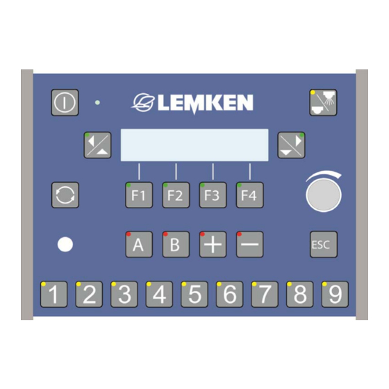
Ecospray operating terminal ECOSPRAY OPERATING TERMINAL The operating terminal is used to operate the electronic control unit. It is connected to the job computer on the implement and among other things, consists of a display, keys, LED indicators and a rotary encoder. Overview Display Rotary en-... -
Page 23: Other Displays
Ecospray operating terminal Other displays This display appears during a work step. Press this key to interrupt the work step. -
Page 24: Segment Box
Segment box SEGMENT BOX Switching of the segment box and the Spray ON/OFF function can be controlled with the segment box. It is connected to the operating terminal and among other things, consists of a display, switches and LED indicators. The segment box is connected with the LIN IN connection on the LIN connection of the operating terminal or to the LIN OUT connection of the joystick box. -
Page 25: Tankpilot Electronic Fill Level Indicator
TankPilot electronic fill level indicator TANKPILOT ELECTRONIC FILL LEVEL INDICATOR The TankPilot electronic fill level indicator displays the fill level on the implement. The TankPilot electronic fill level indicator is located on the implement control cen- tre. The TankPilot electronic fill level indicator is connected to the job computer on the implement and consists, amongst other things, of a display, a button and an LED. -
Page 26: Function
TankPilot electronic fill level indicator Function The TankPilot electronic fill level indicator can show the following displays: Current fill level Maximum fill level alarm Minimum fill level alarm Selector valve position (option) An alarm is displayed when the fill level specified on the operating terminal for that alarm is reached. -
Page 27: Joystick Box
Joystick box JOYSTICK BOX If the implement is equipped with EcoControl, the boom can be completely con- trolled with the joystick box. The joystick box is connected with the LIN IN connection on the LIN connection of the operating terminal or to the LIN OUT connection of the segment box. The active functions of the keys are shown by the LED indicators. -
Page 28: Function
Joystick box Joystick Selection of arm 1 to 5 If the pre-selection of symmetrical folding is not active: Joystick left = Boom left Joystick right = Boom right 10.2 Function The boom can be controlled with the joystick box as soon as the joystick box is connected to the Ecospray operating terminal: ... -
Page 29: Commissioning
Commissioning COMMISSIONING 11.1 Switching the operating terminal on and off 11.1.1 Switching on Press this key to switch on the operating terminal. A brief system check is carried out, in which all LEDs on the keys and all other LEDs illuminate. -
Page 30: 100 M Calibration
Commissioning 11.2 100 m calibration A calibration over 100 m must be performed after the operating terminal is con- nected. If possible, the 100 m calibration must be performed on the area which is to be sprayed with the four-wheel drive [if fitted] switched on ... - Page 31 Commissioning The 100 m calibration running display ap- pears. Drive a distance of 100 m. Press this key to stop the 100 m calibra- tion. Press this key to confirm the 100 m cali- bration. The pulse number is displayed. ...
-
Page 32: Calibration Of Flow Meter
Commissioning 11.3 Calibration of flow meter A calibration of the flow meter must be carried out before the start of each season. To determine the weight of the combina- tion of the tractor and the implement, fill the tank of the implement with water to the nominal fill level. - Page 33 Commissioning If not, switch on the PTO. Allow the pump to run at the specified nominal speed. Refer to the operating instructions for the implement. Press this key to confirm the process. The display that the nozzles are filled ap- pears.
- Page 34 Commissioning Enter the weighed empty weight: Press the rotary encoder to select the value. Turn the rotary encoder to enter the val- Press the rotary encoder to save the value. Press this key to confirm the display. ...
-
Page 35: Selection Of Saved Pulse Numbers For Each Tractor
Commissioning 11.4 Selection of saved pulse numbers for each tractor According to the tractor, the required pulse number can be called up and set as follows. From the settings menu press this key to access the calibration menu. The calibration menu is displayed. ... -
Page 36: Target Quantity
Commissioning 11.5 Target quantity After the 100 m calibration, the target quantity in l/ha must be set. From the settings menu Press this key to access the setup menu. The current target quantity is displayed. Press the rotary encoder to select the number. -
Page 37: Seh Boom
SEH Boom SEH BOOM 12.1 General Partially folding the individual arms of the boom in or out is not permitted. The individual arms must always be folded completely in or out. The boom may only be folded when stationary. Operation of the implement with the boom completely folded out or symmetrically folded is not permitted if the swing lock/locking is engaged. -
Page 38: Operation
SEH Boom 12.1.1 Operation Folding in and out of the SEH Basic and Full booms is controlled via the operating terminal and the control units of the tractor. Folding in and out of the SEH Comfort and Premium booms is controlled via the operating terminal or the joystick box. -
Page 39: Information In The Display
SEH Boom 12.1.4 Information in the display Ecospray operating terminal If the relevant function key for the activation of a function is pressed and held and one or more conditions for the activation of this function are not fulfilled, the corre- sponding information appears in the display. -
Page 40: Versions
SEH Boom 12.2 Versions SEH booms are available in four different versions: Basic Full Comfort Premium The following control units are required: Basic (*) Full (*) Comfort (**) Joystick, Joystick, Joystick, Joystick Joystick, Joystick, right and right and right and right and... -
Page 41: Boom Distribution
SEH Boom 12.3 Boom distribution = Arm 0 = Arm 1 = Arm 2 = Arm 3 = Arm 4 = Arm 5... - Page 42 SEH Boom Permissible reduction of the working width SEH 15 and 18 symmetrically with arms 3, 2 and 1. one-sided on left with arms 3, 2 and 1. one-sided on right with arms 3, 2 and 1. ...
- Page 43 SEH Boom Permissible pivoting of the arms SEH 15 and 18 With arms folded out or reduced up to 20° (1). With arms 1 (-3) folded in by up to 80° (2). SEH 20 and 21 With arms folded out or folded in up to 20°...
-
Page 44: Seh Basic Boom
SEH Boom 12.4 SEH Basic boom 12.4.1 General Press this key to switch on the operating terminal. Before the boom can be folded out: Lift the boom up to the detection position using the control unit. To fold out the booms: ... -
Page 45: Swing Lock
SEH Boom 12.4.2 Swing lock Press one of the keys to pre-select the swing lock function. Use the relevant control unit on the trac- tor to open or close the swing lock. Press one of the keys to cancel the pre- selection. -
Page 46: Folding The Boom Out Symmetrically
SEH Boom 12.4.3 Folding the boom out symmetrically Lift the boom using the appropriate con- trol unit until the folding position is reached. The display for closing the swing lock now appears. Close the swing lock, see »Swing lock, page 45«... - Page 47 SEH Boom Press this key to pre-select arm 2. To fold out arm 2: use the appropriate control unit on the tractor. Press this key or another function key to cancel the pre-selection. To pre-select arms 3, 4 or 5, ...
-
Page 48: Folding The Boom In Symmetrically
SEH Boom 12.4.4 Folding the boom in symmetrically Press this key in the folding menu to fold in the boom symmetrically. Close the swing lock. Bring the boom into the detection posi- tion. The menu for folding the boom symmetri- cally appears. -
Page 49: Seh Full Booms
SEH Boom 12.5 SEH Full booms 12.5.1 General Press this key to switch on the operating terminal. Before the boom can be folded out: lift the boom up to the detection position using the control unit. To fold out the boom: ... -
Page 50: Folding The Boom Out Symmetrically
SEH Boom 12.5.2 Folding the boom out symmetrically Before the boom can be folded out: lift the boom up to the detection position using the control unit. The display for closing the swing lock now appears. Close the swing lock. ... -
Page 51: Folding The Boom In Asymmetrically
SEH Boom 12.5.4 Folding the boom in asymmetrically Press this key in the first folding menu to select the function for folding the boom asymmetrically. Depending on the version of the boom, the first menu for folding the boom asymmetri- cally appears. -
Page 52: Slope Compensator
SEH Boom 12.5.6 Slope compensator Press the key to access the first folding menu. The first folding menu is displayed. Here, the following functions can be con- trolled: Swing lock Folding the boom out symmetrically Folding the boom out asymmetrically ... -
Page 53: Pivoting Of Arm 1
SEH Boom 12.5.7 Pivoting of arm 1 This function enables pivoting of the arms, see page 43. Press the key to access the first folding menu. The first folding menu is displayed. Here, the following functions can be con- trolled: ... - Page 54 SEH Boom Press both keys to pre-select the pivot- ing of the arms on both sides. To adjust the pivoting of the arms on both sides: use the appropriate control unit on the tractor. Press the key or another function key to cancel the pre-selection.
-
Page 55: Seh Comfort And Premium Booms Via The Ecospray Operating Terminal
SEH Boom 12.6 SEH Comfort and Premium booms via the Ecospray operating termi- 12.6.1 General The folding menu for the SEH Comfort and Premium booms has the following structure: 1. Folding menu Folding Folding 4. Folding menu menu menu Activate swing lock ... - Page 56 SEH Boom Press this key to switch on the operating terminal. Before the boom can be folded out: pressurise the control unit of the tractor. To fold out the boom: Press this key to access the 1st folding menu.
- Page 57 SEH Boom 3. Folding menu - boom height Press the key to access the third folding menu. The third folding menu is displayed. Here, the following functions can be con- trolled: Boom height while working [F1] Boom height on headland [F2] ...
-
Page 58: Activating The Swing Lock
SEH Boom 12.6.2 Activating the swing lock The swing lock must be closed before the boom is folded. The swing lock must be opened again after the boom has been fully folded out. To close the swing lock: ... -
Page 59: Folding The Boom In And Out Symmetrically (Comfort Only)
SEH Boom 12.6.3 Folding the boom in and out symmetrically (Comfort only) Ensure that the swing lock is closed before folding out. To fold out the boom symmetrically, press this key. Depending on the version, the menu for folding the boom symmetrically appears. -
Page 60: Automatically Folding The Boom In And Out Symmetrically (Premium Only)
SEH Boom Press this key to fold in arm 2 Press this key to fold in arm 1 12.6.4 Automatically folding the boom in and out symmetrically (Premium only) To automatically fold the boom symmetri- cally, press this key. The menu for automatic folding is dis- played. -
Page 61: Asymmetrical Folding Of The Boom
SEH Boom 12.6.5 Asymmetrical folding of the boom The arms can be folded out in pairs on both sides. For this, the appropriate key must also be pressed. To fold out the boom asymmetrically, press this key. The first menu for folding out the boom asymmetrically appears. -
Page 62: Slope Compensator
SEH Boom Press this key to access the menu for folding the next arm asymmetrically. To fold the corresponding arm: proceed as described above. 12.6.6 Slope compensator To use any slope compensation: Press this key in the second folding menu and the boom will pivot down to the left. -
Page 63: Move To The Boom Height
SEH Boom 12.6.7 Move to the boom height This function enables a pre-set boom height while working and at the headland. The pre-set boom heights can be moved to using the third folding menu. Press this key to set the boom to the pre-set working height. -
Page 64: Pivoting The Arm
SEH Boom 12.6.8 Pivoting the arm The arms can be pivoted on one side using the fourth folding menu. Fully fold out the boom. See »Folding the boom, page 59«. Press this key to move the left arm downwards to the required position. -
Page 65: Seh Comfort And Premium Booms Via The Joystick Box
SEH Boom 12.7 SEH Comfort and Premium booms via the joystick box 12.7.1 General Before the boom can be folded out: Press the key for about 1 second to switch on the joystick box. The boom automatically stops in the detec- tion position. -
Page 66: Symmetrical Folding Of The Boom
SEH Boom 12.7.3 Symmetrical folding of the boom Press this key to select the function for folding out the boom symmetrically. The function is active as soon as the LED illuminates. Press this key to pre-select arm 1. ... -
Page 67: Asymmetrical Folding Of The Boom
SEH Boom 12.7.4 Asymmetrical folding of the boom Press this key to deselect the function for folding the boom symmetrically. The function is inactive as soon as the LED no longer illuminates. Press this key to pre-select arm 1. ... - Page 68 SEH Boom Press this key to pre-select arm 5. Press the left joystick outwards to fold out the left arm 5. Press the right joystick outwards to fold out the right arm 5. Press the relevant joystick inwards to fold in the arms.
-
Page 69: Folding The Boom Automatically (Premium Only)
SEH Boom 12.7.5 Folding the boom automatically (Premium only) Hold this key until the boom is complete- ly folded out. Hold this key until the boom is complete- ly folded in. The LED flashes during the folding pro- cess. -
Page 70: Slope Mirroring
SEH Boom 12.7.7 Slope mirroring Press this key to mirror the slope com- pensation vertically for the next pass. 12.7.8 Middle position Press this key to bring the boom back into the middle position. 12.7.9 Pivoting arm 1 Press this key to pre-select the pivoting function for left arm 1. -
Page 71: Automatic Headland Management (Premium Only)
SEH Boom 12.7.10 Automatic headland management (Premium only) Press this key to start the first step of your customised sequence control, see »Allocation of the Auto key, page 113«. Once the first step has been completed, the LED illuminates continuously. ... -
Page 72: He Booms
HE Booms HE BOOMS 13.1 General Partially folding the individual arms of the boom in or out is not permitted. The individual arms must always be folded completely in or out. The boom may only be folded when stationary. Operation of the implement with the boom completely folded out or symmetrically folded is not permitted if the swing lock/locking is engaged. -
Page 73: Operation
HE Booms 13.1.1 Operation Folding in and out of the boom is controlled via the operating terminal and the control units of the tractor. Depending on the equipment of the implement, the boom can be folded in or out asymmetrically. 13.1.2 Function A function can be pre-selected with the function keys of the operating terminal and controlled with the tractor control unit. -
Page 74: Versions
HE Booms 13.2 Versions HE booms are available in two different versions: Basic Full The following control units are required: Basic (*) Full (*) (*) only in association with Closed Center hydraulic system ew = single-acting tractor control unit dw = double-acting tractor control unit... -
Page 75: Boom Distribution
HE Booms 13.3 Boom distribution = Arm 0 = Arm 1 = Arm 2 Permissible folding of the arms one-sided on the right one-sided on the left symmetrically with arm 2... -
Page 76: He Basic Boom
HE Booms 13.4 HE Basic boom 13.4.1 General Press the key to switch on the operating terminal. The basic menu is displayed. Press this key to access the first folding menu. The first folding menu is displayed. Here, the following functions can be pre- selected. -
Page 77: Swing Lock
HE Booms 13.4.2 Swing lock The swing lock must be closed before the boom can be folded out: Press one of these keys to pre-select the swing lock function. Use the relevant control unit on the trac- tor to open or close the swing lock. ... -
Page 78: Folding Out The Right Boom
HE Booms 13.4.3 Folding out the right boom To fold out the right boom, press this key to pre-select the right arm. Hold this key down. Any information will be displayed. Use the relevant control unit on the trac- tor to fold out the right boom. -
Page 79: He Full Boom
HE Booms 13.5 HE Full boom 13.5.1 General Press the key to switch on the operating terminal. The basic menu is displayed. Press this key to access the first folding menu. The first folding menu is displayed. Here, the following functions can be pre- selected: ... -
Page 80: Swing Lock
HE Booms 13.5.2 Swing lock The swing lock must be closed before the boom can be folded out: Press one of these keys to pre-select the swing lock function. Use the relevant control unit on the trac- tor to open or close the swing lock. ... -
Page 81: Folding Out The Right Boom
HE Booms 13.5.3 Folding out the right boom To fold out the right boom, press this key to pre-select the right arm. Hold this key down. Any information will be displayed. Use the relevant control unit on the trac- tor to fold out the right boom. -
Page 82: Folding Arm 2
HE Booms 13.5.5 Folding arm 2 The arms can be folded in on one side in order to avoid an obstacle while working or to only work with half of the boom width. To pre-select the function for folding back arm 2 on the left, ... -
Page 83: Emergency Switch
Emergency switch EMERGENCY SWITCH 14.1 General This function should only be activated if: the boom is outside of the detection range of the arm pivoting WARNING [SEH booms only] there is a malfunction of the sensors on the boom. The sensors must then be checked or another folding function must firstly be performed, in order to carry out the required func- tion. -
Page 84: Joystick Box
Emergency switch 14.4 Joystick box The following functions of the boom can be controlled via the joystick box using the emergency switch: Pivoting arm 1, on one or both sides Folding in and out Press the appropriate key to activate the required function. -
Page 85: Filling The Main Tank
Filling the main tank FILLING THE MAIN TANK 15.1 Implement without electronic fill level display Fill the tank to the required fill level. Press the key to switch on the operating terminal. Press the key to access the settings menu. - Page 86 Filling the main tank Press the key for 3 seconds to save the maximum quantity. The word "SAVE" appears in the display. Press the key to access the residual quantity alarm display. The residual quantity alarm display ap- pears.
-
Page 87: Implement With Electronic Fill Level Display
Filling the main tank 15.2 Implement with electronic fill level display Press this key to switch on the operating terminal. Press this key to access the settings menu. Press this key to access the tank menu. The current filling quantity is displayed (the filling quantity is determined theoretically). - Page 88 Filling the main tank The residual quantity alarm display ap- pears. ON = On OFF = Off The residual quantity alarm is triggered as soon as the set residual quantity is reached. Press the rotary encoder to select the displayed value.
-
Page 89: Operation
Operation OPERATION 16.1 General After the operating terminal is switched on, the basic menu appears. This consists of two windows. 16.1.1 First basic menu The first basic menu is displayed after the operating terminal is switched on. The first basic menu consists of further menus: Settings Information... - Page 90 Operation The first basic menu is displayed. Press this key to access the settings menu. In the settings menu, the following further menus can be accessed: Implement setup [F1], see »page 91« Tank [F2], see »page 100« ...
-
Page 91: Setting Up The Implement
Operation 16.2.1 Setting up the implement In the implement setup menu, the following further menus can be accessed: Distribution quantity Increase or decrease quantity levels Minimum control speed Height of the boom on the headland [on- ly for SEH Comfort and Premium booms] ... - Page 92 Operation 16.2.1.1 Distribution quantity Press this key to access the implement setup menu. The distribution quantity in l/ha appears. Press the rotary encoder to select the value. Turn the rotary encoder to enter the val- Press the rotary encoder to save the value.
- Page 93 Operation 16.2.1.3 Minimum control speed If the actual speed is below the minimum speed setting, the minimum speed is used for control purposes. This can prevent too sharp a reduction in spray pressure when moving into posi- tion. Press this key to access the display for minimum control speed in km/h.
- Page 94 Operation 16.2.1.4 Height of the boom on the headland [for SEH Comfort and Premium booms only] Press this key to access the display of the boom height on the headland. The display appears. Press these keys to bring the boom into the required position.
- Page 95 Operation 16.2.1.6 Moving to lifting mast height If this function is active, the lifting mast moves to the saved lifting mast height when the main switch is pressed. Main switch: on = the lifting mast moves to the saved operating position ...
- Page 96 Operation 16.2.1.7 Simulated driving speed If the speed signal fails, there is the possibility of using a simulated driving speed in order to complete the work which has been started. Press this key to access the display of the simulated driving speed in km/h. The simulated driving speed in km/h ap- pears.
- Page 97 Operation 16.2.1.8 Maximum spray pressure According to the type of nozzle, the maximum spray pressure can be adjusted be- tween 1 and 10 bar. Press this key to access the maximum spray pressure display. The maximum spray pressure in bar ap- pears.
- Page 98 Operation 16.2.1.10 Manual reduction of outer segments If nozzles are sealed, e.g. with plugs, the outer left and right segments must be reduced manually according to the sealed nozzles. The outer segments on the left and right can be reduced in 50 cm steps by up to 1.50 m. ...
- Page 99 Operation 16.2.1.11 Automatic swing lock [SEH Booms only] Press this key to access the automatic swing lock display. The automatic swing lock display appears. ON = For symmetrical folding out of the last arm: the swing lock is opened auto- matically for symmetrical folding in of the last arm:...
-
Page 100: Tank Menu
Operation 16.2.2 Tank menu In the tank menu, the following further menus can be accessed. Current filling quantity Zero quantity [only for implements with- out electronic fill level display] Maximum fill level Residual quantity alarm Press this key from the settings menu to access the tank menu. - Page 101 Operation 16.2.2.2 Zero quantity [only for implements without electronic fill level dis- play] Under certain circumstances it may be necessary to enter the zero quantity in the operating terminal immediately. Press this key to access the zero- quantity display. The zero-quantity display appears.
- Page 102 Operation 16.2.2.4 Residual quantity alarm The residual quantity alarm is triggered as soon as the set residual quantity is reached. Press this key to access the residual quantity alarm display. The residual quantity alarm display ap- pears. ON = On ...
- Page 103 Operation 16.2.2.5 Maximum fill level alarm The maximum fill level alarm gives a warn- ing when the specified maximum fill level is reached. Press this key to access the display for the maximum fill level alarm. The display for the maximum fill level alarm appears.
-
Page 104: Calibration Of Flow Meter
Operation 16.2.3 Calibration of flow meter Press this key from the settings menu to access the flow meter calibration menu. In the flow meter calibration menu, the fol- lowing further menus can be accessed: Manual setting of the pulses per litre ... - Page 105 Operation 16.2.3.3 Calibration using the measuring cup method Fill the tank of the implement with water to the nominal fill level. Drive with the implement onto a level, unsurfaced area, where the water can easily soak away. Allow the pump to run at the specified nominal speed.
- Page 106 Operation Measure the output volume collected. Multiply this by the number of nozzles that were active during calibration. Enter the total volume calculated: Press this key. Press the rotary encoder to select the value. Press the rotary encoder to enter the value.
-
Page 107: 100 M Calibration
Operation 16.2.4 100 m Calibration Press this key from the settings menu to access the 100 m calibration menu. In the 100 m calibration menu, the follow- ing further menus can be accessed: Manual pulse setting [F1] 100 m Calibration [F2] ... - Page 108 Operation 16.2.4.2 100 m Calibration Press this key to access the 100 m cali- bration menu manually. A display with the current pulse number appears. Now start the 100 m calibration. See »100 m calibration, page 30«. 16.2.4.3 Tractor selection ...
-
Page 109: Operating Terminal Settings
Press the rotary encoder to save the symbol. LEMKEN will not accept liability for consequential damage caused by the failure of a speed signal due to shadowing. 16.2.5 Operating terminal settings Press this key from second window of the settings menu to access the operat- ing terminal settings menu. - Page 110 Operation 16.2.5.1 Key sound The key sound for the segment switch and the spray switch can be switched on or off. The key sound display appears. Here, the key sound can be switched on or off. ON = On ...
- Page 111 Operation 16.2.5.2 Scrolling function The scrolling function can be set to auto- matic or manual. This results in a different operational mode: AUTO = The operating menu can be accessed directly by pressing the Spray ON/OFF key. OFF = By pressing the Spray ON/OFF key, the current display is re- tained.
-
Page 112: Joystick Box Settings
Operation 16.2.6 Joystick box settings Press this key from second window of the settings menu to access the joystick box settings menu. In the joystick box settings menu, the fol- lowing further menus can be accessed: Assignment of the Auto key [F1] ... - Page 113 Operation 16.2.6.1 Assignment of the Auto key Here, a customised sequence control can be programmed. There are five different procedures, which can be saved in eight steps: Main switch Spray ON / OFF Height of the boom while working ...
- Page 114 Operation 16.2.6.2 Assignment of the boom pivoting function Press this key to access the boom pivot- ing display. The selection for the assignment of the boom pivoting function appears. Here, the pivoting of the boom can be set with the joystick: ...
-
Page 115: Proportional Valve Settings (Only In Comfort And Premium)
Operation 16.2.7 Proportional valve settings (only in Comfort and Premium) The viscosity of the oil may vary depending on the tractor and environmental fac- tors; as a result it may be necessary to change the proportional valve settings. Press this key in the second window of the settings menu to access the propor- tional valve settings menu. - Page 116 Operation Press this key to open the different views. Raise lift mast Lower lift mast Fold arm 1 in Fold arm 1 out Fold arms 2 to 5 in Angle individual arm upwards ...
-
Page 117: Information Menu
Operation 16.3 Information menu Switch on the operating terminal. The first basic menu is displayed. Press this key to access the information menu. The following menus can be accessed from the information menu: Counters [F1], see »page 117« ... - Page 118 Operation 16.3.1.1 Hectare counter The hectare counter provides information about the area which has been sprayed. The hectare counter begins to count as soon as the Spray ON/OFF key is pressed. Here, the following hectare counters can be called up: ...
- Page 119 Operation 16.3.1.2 Litre counter The litre counter provides information about the number of litres which have been used. The litre counter begins to count as soon as the Spray ON/OFF key is pressed. The following litre counters can be called ...
- Page 120 Operation 16.3.1.3 Working time counters The working time counters provide infor- mation about the working time. The work- ing time counters begin to count as soon as the Spray ON/OFF key is pressed. The following working time counters can be called up: ...
-
Page 121: Sensors
Operation 16.3.2 Sensors The current status of the sensors can be displayed in the sensor information menu. Press this key to access the sensors menu from the information menu. The sensors menu is displayed. Turn the rotary encoder to display the status of the required sensor. - Page 122 Operation ON/OFF- Indicates whether the cur- rent nozzle is switched on or = Nozzle switched on = Nozzle switched off CAN - Indicates whether the selected nozzle has been recognised by the system. = Nozzle with the number selected has successfully registered with the system X = Nozzle with the number...
-
Page 123: Fault Messages
Operation 16.3.4 Fault messages The current status of pending alarms can be displayed in the fault messages infor- mation menu. Press this key to access the fault mes- sages menu from the information menu. The fault messages information menu is displayed. -
Page 124: Implement
Operation 16.3.5 Implement The current values for the implement are displayed in the implement information menu. Press this key from the second window of the information menu to access the implement menu. Here, the following displays can be called ... -
Page 125: Voltage
Operation 16.3.7 Voltage The current voltage is displayed in the voltage information menu. Press this key from the second window of the information menu to access the voltage menu. The voltage information menu is displayed. 16.3.8 Motors and valves The following motors and valves can be switched manually in the motors and valves information menu:... -
Page 126: Folding Menu
Operation 16.4 Folding menu The boom can be folded in or out via the folding menu. Switch on the operating terminal. The first basic menu is displayed. Press this key to access the folding menu. 16.4.1 Folding out the SEH Basic boom See folding out the SEH Basic boom, »page 46«. -
Page 127: Folding Out The He Basic Boom
Operation 16.4.9 Folding out the HE Basic boom See folding out the HE boom, »page 78«. 16.4.10 Folding in the HE Basic boom See folding in the HE boom, »page 78«. 16.4.11 Folding out the HE Full boom See folding out the HE boom, »page 81«. 16.4.12 Folding in the HE Full boom See folding in the HE boom, »page 81«. -
Page 128: Operating Menu
Operation 16.5 Operating menu The operating menu can be displayed while working on the field. Switch on the operating terminal. The first basic menu is displayed. Press this key to access the operating menu. In the operating menu, the following infor- mation can be set for permanent display: ... - Page 129 Operation Press this key to change the display of the information listed above. Press this key to select from the follow- ing menus: Slope gradient and boom position Angle of the boom Manual or automatic mode setting ...
-
Page 130: Electronic Selector Valve (Optional)
Operation 16.5.1 Electronic selector valve (optional) If your implement has an electronic selec- tor valve, its suction positions can be se- lected using the control system. Press this key in the operating menu to activate the electronic selector valve functions. - Page 131 Operation 16.5.1.2 Operation via Ecospray Choose the selector valve position re- quired by pressing the relevant function button. The selector valve moves to the corre- sponding position. When the selector valve has reached the position selected, the LED on the corre- sponding function button lights up.
-
Page 132: Nozzle Cleaning Menu
Operation 16.6 Nozzle cleaning menu Switch on the operating terminal. The first basic menu is displayed. Press this key. The second basic menu is displayed. Press this key to access the nozzle cleaning menu. For automatic nozzle cleaning, the boom must be unfolded, the PTO switched on and the main tank already cleaned;... -
Page 133: Working Headlights
Operation 16.7 Working headlights Press this key to switch the working headlights on or off. ON = On OFF = Off 16.8 All-round light Press this key to switch the all-round light on or off. ON = On ... -
Page 134: Use On The Field
Use on the field USE ON THE FIELD 17.1 General Work on the field can begin once the im- plement has been appropriately prepared. Switch on the drive shaft. Check the set spray pressure. Press the key to start spraying. The LED on the key shows the status of the Spray ON/OFF keys: Spray... -
Page 135: Setting The Pressure Manually
Use on the field 17.2 Setting the pressure manually Manual pressure setting can be used when: the working width has been reduced [ex- cept via segment control], there is no signal from the flow meter, national plant protection regulations de- mand manual pressure setting. -
Page 136: Increased Or Decreased Quantity Control
Use on the field 17.3 Increased or decreased quantity control During work, the target distribution quantity can be increased or decreased in pre-set percentage steps. The increased or decreased quantity set is displayed in % in the operating menu. The target distribution quantity flashes if an increased or decreased quantity is active. -
Page 137: Matrix Operating Terminal
Use on the field 17.4.2 Matrix operating terminal If a segment or several segments are acti- vated, they can be controlled or switched on or off via the matrix operating terminal. Ecospray operating terminal segment switch status Switched on Switched off BoomPilot Matrix Activated Segment control via the ma-... -
Page 138: Faults
Faults FAULTS 18.1 General Fault messages are generally indicated as follows: An acoustic signal sounds Fault message in the display LED lights up red Fault messages can be displayed in the following categories: Category Message Warning/Fault/Information Cable break Short-circuit System fault ... -
Page 139: Categories B To D
Faults 18.2.2 Categories B to D Press this function key to deactivate the message. The deactivated messages are displayed again after a restart of the Ecospray oper- ating terminal. Once the fault has been remedied, the red LED goes out. 18.3 A –... - Page 140 Faults Code Group Description Possible cause Remedies Remaining quan- Refill Information Minimum fill level Correct the entry reached tity reached Incorrect entry Check the sen- Possible incorrect sensor value for electronic fill level indicator ...
-
Page 141: B - Cable Breaks
Faults Code Group Description Possible cause Remedies tions PTO speed too Reduce PTO Information Maximum pump speed exceeded high speed Nozzle faulty Check nozzle Fault Fault in nozzle Wiring faulty control system status in the in- formation menu ... -
Page 142: C - Short-Circuit
Faults Code Output Description Possible cause Remedies Visual inspection Y22 oil circulation, Cable connection Replace cable if ne- 4/3-way valve defective cessary Visual inspection Y23 oil circulation, Cable connection Replace cable if ne- 3/3-way valve defective cessary ... - Page 143 Faults Code Output Description Possible cause Remedies Visual inspection Swing lock valves Cable connection Replace cable if ne- Y18/Y19 defective cessary Visual inspection Slope compensation Cable connection Replace cable if ne- valves Y20/21 defective cessary Visual inspection Y22 oil circulation, Cable connection ...
- Page 144 Faults Code Output Description Possible cause Remedies Visual inspection TB7 Segment 7 Cable connection Replace cable if ne- defective cessary Visual inspection HA10 TB8 Segment 8 Cable connection Replace cable if ne- defective cessary Visual inspection HA11 TB9 Segment 9 Cable connection...
-
Page 145: D - System Fault
Faults 18.6 D – System fault These vary according to the version of the implement. Code Description Possible cause Remedies Visual inspection Connecting plug missing Replace cable if necessa- Defective bus cable Defective job computer plug ... -
Page 146: Alarms
Faults 18.7 Alarms 18.7.1 Segment box Code Description Possible cause Remedies Switch off the operating Defective log-in to the op- Defective initiali- terminal and then switch it sation process erating terminal on again Check the connections Segment box connected ... -
Page 147: Position And Safety Sensors
Position and safety sensors POSITION AND SAFETY SENSORS 19.1 SEH Boom To facilitate operation and for safety reasons, sensors detect the various states of the boom. The number and type of the sensors may vary according to the version of the boom. - Page 148 Position and safety sensors Sensor Abbreviation Pressure sensor Flow meter Tank content Swing lock closed Swing lock open Basic Full Comfort Premium Middle position, slope compen- sation Slope compensation position Height adjustment Flow monitor S15/16 S15/16 Arm 1 (-5), left Arm 1 (-5), right Arm 2 (-5), left Arm 2 (-5), right...
- Page 149 Position and safety sensors Abbre- Function Description viation Pressure sensor The pressure sensor detects the pressure in the im- plement. The pressure is displayed on the operating terminal as the spraying pressure. is displayed as the EltecBase circulation system pressure when the nozzles are switched off (SEH boom).
- Page 150 Position and safety sensors Fold arms 1 (-5) Factory setting; approx. 10 cm above the boom rest. This position of the boom height enables vertical folding of the arms 1 (-5). Fold arms 2 (-5) Factory setting; approximately the middle position between "Fold arms 1 (-5)"...
-
Page 151: He Booms
Position and safety sensors 19.2 HE Booms To facilitate operation and for safety reasons, sensors detect the various states of the boom. The number and type of the sensors may vary according to the version of the boom. Sensor Function ... -
Page 152: Disposal
Disposal DISPOSAL After the end of its service life, the implement must be disposed of by a specialist in an environmentally friendly manner. Metal and plastic components must be recycled. When disposing of the implement, ensure that individual components and operating materials are disposed of in an environmentally friendly manner.
Need help?
Do you have a question about the Ecospray Sirius 10 and is the answer not in the manual?
Questions and answers