Advertisement
Quick Links
®
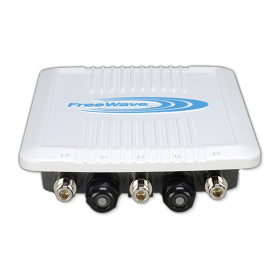
WAVEPRO
WP201-100
Thank you for purchasing the WAVEPRO WP201 Access Point.
This Quick Start Guide provides procedures for the initial setup of the WP201-
100.
Note: For detailed information about network functionality and deployment
scenarios, download the WP201 User Manual from
http://support.freewave.com/.
WP201-100 Included Equipment
Included Equipment
Qty
Description
1
WP201-100 Quick Start Guide
1
WP201-100 Access Point
1
Mounting Bracket
2
Green / Yellow #10AWG Ground Cables
1
Pole Mounting Bracket
1
Universal Power Adapter
2
Band Clamps
1
PoE+ Injector
1
Packaged Ground Screw
3
7dBi 5GHz omni-directional antennas
3
5dBi 2.4GHz omni-directional antennas
1
Mounting Kit Package (includes screws, masonry
wedge anchor bolts)
Note: For additional equipment, see Available Accessories in the WP201
User Manual.
Figure 1: WP201 Included Equipment
QSG0027AA Rev Aug-2017
User-supplied Equipment
Computer with:
l
an Ethernet port.
l
Windows® 7 or greater.
l
Internet Browser: Chrome®, Firefox®, Internet Explorer®, Opera®,
l
Safari®.
Caution: The default browser in Windows® 10 is Microsoft®
Edge. The WP201-100 software does NOT automatically
download to the computer using Edge. Use one of the other
identified browsers instead.
Qty-2: CAT5e / CAT6 Ethernet cables WITHOUT strain relief
l
Broadband Internet Service (Cable or DSL Modem)
l
Connect to the WP201-100 Access Point
Power Notes
Image
The Universal Power Adapter operates from voltages 100 to 240VAC,
Letter
l
50-60Hz.
The WP201-100 is powered through the E1 Port (PoE Input) by any PSE
l
(Power Sourcing Equipment) which supports IEEE 802.3at (PoE+)
including the provided PoE+ Injector.
A
Procedure
B
1. Remove the protective caps from the antenna ports.
C
2. Attach using a strong hand-tighten the 2.4GHz and 5GHz antennas to their
D
same-labeled antenna ports on the WP201-100.
E
3. If applicable, replace the protective caps on unused antenna ports.
4. Remove the compression gland assembly from the E1 Port (PoE Input).
F
5. Thread one end of the Ethernet cable through the cap of the compression
G
gland.
H
6. Insert the compression gland onto the Ethernet cable.
7. Connect the assembled Ethernet cable (WITHOUT strain-relief) to the E1
H
Port (PoE Input) of the WP201-100 and the other end into the AP/Bridge
I
port on the PoE+ Injector.
Figure 2: Compression Gland on the CAT5e / CAT6 Ethernet
8. Tighten the compression gland cap on the E1 Port (PoE Input).
9. Connect the second Ethernet cable to the Network port of the PoE+
Injector and to the Ethernet port on the computer.
10. Connect the Power Adapter to the DC IN port of the PoE+ Injector and
plug the other end into an AC electrical outlet.
11. Attach the loop end of one of the supplied Ground Cables to the Ground
screw on the PoE+ Injector.
12. Attach the wire end of the Green / Yellow #10AWG Ground Cable to an
earth / safety ground (the loop end was attached to the WP201 in a previous
step).
Page 1 of 4
cable attached to the E1 Port (PoE Input)
Copyright © 2017 FreeWave
Advertisement

Subscribe to Our Youtube Channel
Related Manuals for FreeWave WAVEPRO WP201-100


Summary of Contents for FreeWave WAVEPRO WP201-100
- Page 1 12. Attach the wire end of the Green / Yellow #10AWG Ground Cable to an earth / safety ground (the loop end was attached to the WP201 in a previous step). Figure 1: WP201 Included Equipment QSG0027AA Rev Aug-2017 Page 1 of 4 Copyright © 2017 FreeWave...
- Page 2 7. Click Properties. The Internet Protocol Version 4 (TCP/IPv4) Properties dialog box opens. 8. Make a note of the current settings (to reverse this procedure later). QSG0027AA Rev Aug-2017 Page 2 of 4 Copyright © 2017 FreeWave...
- Page 3 Figure 17: WP201-100 Firmware window 6. Click the firmware link. 2. Click the Browse button. The Firmware Upgrade window opens. 3. Locate and select the upgrade .BIN file downloaded from the FreeWave 7. Select and click the attachment. website. 4. Click Open.
- Page 4 FreeWave Technologies, Inc. reserves the right to make changes to this document or the product described within it without notice. FreeWave assumes no responsibility or liability for the use of this document or the 4. In the Access Panel on the left, click Basic.
Need help?
Do you have a question about the WAVEPRO WP201-100 and is the answer not in the manual?
Questions and answers