
Related Manuals for NEXTIVITY Cel-Fi QUATRA RED


Summary of Contents for NEXTIVITY Cel-Fi QUATRA RED
- Page 1 ® CEL-FI QUATRA RED Installation and User Guide Draft Nextivity, Inc. 16550 West Bernardo Dr. Building 5, Suite 550 San Diego, CA 92127 858-485-9442 9/10/2019...
-
Page 2: Copyright
Nextivity Inc., except in the case of brief quotations embodied in critical reviews and specific other noncommercial uses permitted by copyright law. -
Page 3: Table Of Contents
CONTENTS Copyright ..............................2 Disclaimer of Liability ..........................2 Revision History ............................2 Change List ..............................2 CONTENTS ..............................3 Table of Figures ............................6 GENERAL INFORMATION ..........................7 Safety Notices ............................7 INTRODUCTION ............................9 System Overview ............................9 QUATRA RED Architecture........................ - Page 4 CU unpacking and package content ....................21 CU ports layout ........................... 23 Coverage Unit (CU) Mounting ......................23 CU Grounding ............................. 24 CU user interface ..........................25 REMOTE ANNUNCIATOR PANEL (RA) ....................26 RA unpacking and package content ....................26 RA ports layout ...........................
- Page 5 Isolation calculation and setting ......................38 Uplink output power configuration ......................39 Band configuration (FirstNet) ......................39 Channel configuration (LMR) ......................39 Alarms configuration and test ......................39 LEDs ................................39 NU ................................40 CU ................................40 QRE ................................ 40 Antennas and QUATRA RED ........................
-
Page 6: Table Of Figures
Table of Figures Figure 1. QUATRA RED System Architecture ....................10 Figure 2. Waterproof RJ45 Inline connector assembly ................13 Figure 3. MBBU Wall Mounting ........................14 Figure 4. Batteries inside MBBU (Place holder)..................15 Figure 5. Battery connection scheme (Place holder) .................. 15 Figure 6. -
Page 7: General Information
GENERAL INFORMATION Safety Notices Electric Shock Opening any of the QUATRA RED components may result in electric shock and may cause severe injury Exposure to RF Working with the equipment while in operation may expose the technician to RF electromagnetic fields that exceed FCC rules for human exposure. - Page 8 Warranty Opening or tampering with any of the QUATRA RED components voids all warranties. Lithium battery The battery may explode if it's replaced by an incorrect type. Dispose of used batteries according to instructions. Ethernet instructions This equipment is for indoor use only. All cabling should be installed indoors. 9/10/2019...
-
Page 9: Introduction
QUATRA RED system. System Overview Cel-Fi QUATRA RED solution consists of a Network Unit (NU) and up to six (6) Coverage Units (per NU). The Network Unit takes off-air signals from two available donor antenna ports (LMR and LTE) and digitizes the RF signals for distribution to up to six Coverage Units (CU) over dedicated Category (Cat5e or better) cables. -
Page 10: Quatra Red Architecture
Emergency Power-Off Switch (EPO) Cel-Fi by Nextivity recommends the use of Category cable (CAT5e or superior) for data transmission and to provide electrical power supply (Power-over-Ethernet) to all the components in the system except were is indicated in this user manual. -
Page 11: Main Features
Cel-Fi QUATRA RED NU, FirstNet + 700/800MHz LMR F41-8XCU Cel-Fi QUATRA RED CU, FirstNet + 700/800MHz LMR F42-10L-100 Cel-Fi QUATRA RED MBBU Large (for systems w/ 3 to 6 CUs; 12 Hrs) F42-10S-100 Cel-Fi QUATRA RED MBBU Small (for systems w/ 1 to 2 CUs) F42-10X-100 Cel-Fi QUATRA RED MBBU Large (for systems w/ 3 to 6 CUs;... -
Page 12: Installation
INSTALLATION Installation Area All the components of the QUATRA RED solution are NEMA 4 rated; however, temporary protection should be taken when the equipment packaging is opened for installation or maintenance in an outdoor environment. The installation location for the product must be well ventilated. The equipment has been designed to operate at the temperature range and humidity level, as stated in the product specifications. -
Page 13: Waterproof Rj45 Inline Connectors Assembly
Waterproof RJ45 Inline connectors assembly This section applies to all the components in the Cel-Fi QUATRA RED solution using RJ45 connectors. Use a CAT 5e cable or higher category to interconnect the units. Each QUATRA RED component includes a set of waterproof RJ45 inline connectors to be installed on each side of the Ethernet cable. -
Page 14: Figure 3. Mbbu Wall Mounting
Caution. Make sure the area behind any surface is free of electrical wires or other dangerous elements before drilling. 1. To mount the MBBU, first determine the approximate location on the wall for the unit. 2. Hold the unit against the wall and use a pencil or similar marker to mark the top and bottom anchor points. -
Page 15: Mbbu Battery Connections
MBBU Battery connections 1. Ensure both circuits breakers A & B (AC and Batteries) are in the OFF position. 2. Install batteries into enclosure per Figure 5. 3. Connect the battery series jumpers, as indicated in Figure 6. 4. Connect battery cables from circuit breaker B (Battery Breaker) and DC ground terminal block to 48-volt battery string terminals, as shown in Figure 7. -
Page 16: Mbbu Power Supply Connection
Figure 6. Battery connection diagram MBBU Power Supply Connection 1. Connect the AC power cord to standard 115 VAC outlet 2. Turn ON circuit breaker A (AC Power) and verify the battery controller AC-OK LED turns on solid green (Figure 8). 3. -
Page 17: Figure 7. Ac Ok Led
Figure 7. AC OK LED 9/10/2019... -
Page 18: Network Unit (Nu)
Network Unit (NU) The Network Unit is referred to as the NU and itis the signal processing head end for the QUATRA RED system. The signal sources (LMR & LTE) are connected to the NU, digitized, and distributed over Category cable to the Coverage Units. -
Page 19: Nu Mounting
NU Mounting The Cel-Fi QUATRA NU is designed to be wall-mounted. Mounting accessories, including screws and anchors for common material types (drywall, plywood, etc), are included in the standard kit. The QUATRA RED NU has four (4) secure mounting tabs, two on each side. The two topmost tabs have been keyholed to allow the unit to hang from preinstalled wall anchors. -
Page 20: Donor Antenna Connection
Figure 11. Grounding the NU Donor antenna connection Connection to the donor antennas is made via two Type-N female connectors. The RF connector labeled "LMR" must be connected to the antenna pointing towards the LMR base station. The LMR port can receive both 700 and 800MHz public safety signals. -
Page 21: User Interface
User Interface The table below shows the LED interface (front) to indicate system status. State Power NORMAL OP HARDWARE ERROR CONNECTED BUT NOT RELAYING NETWORK SCANNING LAN CONNECTED LAN ERROR SFP HARDWARE INSTALLED/READY SFP CONNECTED SOFTWARE ERROR Coverage Unit (CU) The Coverage Unit (CU) receives the digitized signal from the NU, converts back to RF, boosts, and distributes the service from its RF port. - Page 22 Check that all the items listed in the packing list are included. 9/10/2019...
-
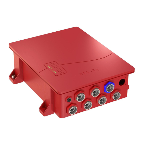
Page 23: Cu Ports Layout
CU ports layout The Coverage Unit (CU) has one N-type female connector for RF signals; one PoE port for communication with the Network Unit (NU) and a LAN port for local connection to the unit. N-type Female connector LAN port Data / PoE port Figure 14. -
Page 24: Cu Grounding
Figure 15. CU Mounted on a wall CU Grounding 1. Connect one side of the grounding cable to the grounding terminal on the equipment with a ¼" – 20 Bolt. 2. Connect the other end to the main grounding bar installed inside the fire room. The recommended cable gauge is AWG #10 or AWG #12 and color code green/yellow. -
Page 25: Cu User Interface
CU user interface The table below shows the LED interface (front) to indicate system status. Label NORMAL OPERATION ERROR CONDITION AT THE NU ERROR CONDITION AT THE CU 9/10/2019... -
Page 26: Remote Annunciator Panel (Ra)
REMOTE ANNUNCIATOR PANEL (RA) Cel-Fi QUATRA RED Remote Annunciator Panel provides automatic supervisory signals for malfunctions of the ERRCS. It includes FORM-C dry relay contacts compatible with any fire alarm control unit (open or short circuits). Figure 17. Remote Annunciator Panel RA unpacking and package content Examine the box for damage before unpacking the unit. - Page 27 9/10/2019...
-
Page 28: Ra Mounting
RA Mounting The Remote Annunciator is designed to be wall-mounted. Mounting accessories, including screws and anchors, for common material types (drywall, plywood, concrete) are included in the standard kit. The QUATRA RED RA has two (2) secure mounting tabs, one on each top/bottom side. Caution. -
Page 29: Ra Ethernet Connection
RA Ethernet connection Remote annunciator connection to the MBBU is thru a PoE (Power Over Ethernet) cable. You can find assembly instructions on page 12 of this manual. Form-C cable connection to Fire Alarm Control Panel Included in the box is a Form-C cable with three pins per alarm. The first one is a normal-close signal, the second one is a common signal, and the third is a normal-open signal. -
Page 30: Ra User Interface
Figure 21. Alarm Cable Configuration RA user interface The table below shows the color coding for any alarm condition in the Remote Annunciator. LEDs will be OFF if there is no alarm. If an alarm is present LEDs will be RED. If there is a communications fault (open, shorted to ground or disconnected cable) between the Fire Alarm Control Unit and the Remote Annunciator Panel, the LEDs will flash. -
Page 31: Emergency Power-Off Switch (Epo)
EMERGENCY POWER-OFF SWITCH (EPO) Cel-Fi's QUATRA RED Emergency Power Off Switch (EPO) can instantaneously shut down the ERRCS from a single point to eliminate the risk of combustion caused by electricity or static. Designed to prevent inadvertent operation and can be installed in any location acceptable to the authority having jurisdiction. Figure 23. -
Page 32: Epo Mounting
EPO Mounting The Emergency Power-off Switch (EPO) is designed to be wall-mounted. Mounting accessories, including screws and anchors, for common material types (drywall, plywood, concrete) are included in the standard kit. The QUATRA RED EPO has two (2) secure mounting tabs, one on each top/bottom side. Caution. -
Page 33: Epo Operation
EPO Operation In the scenario of an emergency, it might be necessary to shut down all the radio communication systems. 1. Locate the EPO and press the bottom to automatically turn-off all the QUATRA RED units, including the MBBU. 2. To turn the system back on, twist the EPO button clockwise, then follow the instructions on the WAVE PRO APP. -
Page 34: Quatra Red System Configuration
QUATRA RED SYSTEM CONFIGURATION Once you have all the QUATRA RED components installed and energized, the next step is to configure and commission the system. The general process to commission QUATRA RED is explained in the next figure 1. Request Access to 1. -
Page 35: Cel-Fi Wave Portal
Cel-Fi WAVE Portal For channel partners and installers, the WAVE portal is a cloud-based management solution to keep track of systems in the field. • Commissioning • Alerts & Alarms • Status & Email/Text Notifications • Troubleshooting WAVE Architecture MBBU Internet Connection & WAVE Portal Account Monitor and Battery Backup requirements ... -
Page 36: Wave Pro App
1. Click on the "File Manager" button on the left side menu 2. Click on the "Add Config File" button, enter a name for the new config file, and click "Add" to save your file. 3. A new window will open for you to enter isolation values and frequencies according to the requirements in your area. -
Page 37: Wave Pro And Compass
WAVE PRO and COMPASS Introduction COMPASS is Nextivity's site survey and installation tool. The UI for COMPASS is WAVE PRO (iOS and Android). It is a complete solution to allow integrators to install and optimize a QUATRA RED installation without the need for local Internet connectivity. -
Page 38: Compass Features And Functions
These ports cannot be reassigned or reconfigured. Each donor can be established to the system via off-air. A directional antenna is recommended to provide the best signal quality. (Nextivity offers many directional antennas that can be used. See www.cel- fi.com/products... -
Page 39: Uplink Output Power Configuration
Uplink output power configuration In this section, you will learn how to set a value for the output transmit power to reach the high-site without blocking the receiver. Two pieces of information are required to determinate the most optimal value. Decimal coordinates from both the high-site and QUATRA RED and the desired signal level reaching the remote site (the default value is -95dBm). -
Page 41: Antennas And Quatra Red
Antennas and QUATRA RED Donor Antennas The donor antenna is a crucial element when designing a public safety DAS. Typically this component is mounted on the roof of the building and is exposed to signal interference caused by reflections or direct signals hitting the antenna from every direction. -
Page 42: The Wave Portal
© 2019 Nextivity Inc. All rights reserved. All trademarks identified by ® or ™ are registered trademarks or trademarks, respectively, of Nextivity, Inc. This document is for planning purposes only and is not intended to modify or supplement any specifications or warranties relating to...
Need help?
Do you have a question about the Cel-Fi QUATRA RED and is the answer not in the manual?
Questions and answers