
Related Manuals for Holzstar ADH Series


Summary of Contents for Holzstar ADH Series
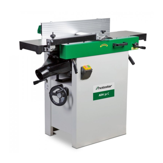
- Page 1 Operating Instructions Planer-Thicknesser ADH 26 C 230V, 400V ADH 31 C 230V, 400V ADH 41 C 400V ADH 26 C ADH 31 C...
-
Page 2: Table Of Contents
Fax: 0049 (0) 951 96555-55 5.3 Storage ............. 12 6 Description of device ..........12 E-Mail: info@holzstar.de 7 Setting up and connection ........12 URL: www.holzstar.de 7.1 Requirements for the place of operation ..12 7.2 Setting up of the Planer-Thicknesser....13 7.3 Electrical connection ........ -
Page 3: Introduction
All data in this operation manual has been compiled on You have made an excellent choice in purchasing a the basis of the state-of-the-art, valid standards and gui- HOLZSTAR Planer-Thicknesser. delines as well as our many years of expertise and ex- perience. -
Page 4: Operator Responsibility
Safety - Operators shall obtain information about valid oc- cupational safety regulations and determine addi- ATTENTION! tional hazards as part of a risk assessment which This combination of symbol and signal term indica- result from the specific operating conditions at the tes a potentially hazardous situation which may machine's installation location. -
Page 5: Personal Protective Equipment
Safety Operating staff: Protective dust-mask Operating staff has undergone an induction by the ope- rator about the entrusted tasks and potential hazards The dust protection mask protects the respiratory resulting from improper behaviour. Tasks which go tract from wood chips and wood dust. beyond normal operation may only be carried out by the operator if they are listed in the operation manual and the operator has made him/herself familiar with them. -
Page 6: Safety Labels On The Planer-Thicknesser
Safety 2.5 Safety labels on the Planer-Thicknesser 2.6 For your own safety The following safety labels and instructions are attached to the Planer-Thicknesser s (Fig. 1) and must be WARNING! observed. - A planer-thicknesser is a dangerous machine that can cause serious injury if left unattended. It is the- refore essential that you follow the following safety instructions: - The planer-thicknesser may only be put into opera-... -
Page 7: Safety Equipment
Safety Danger of overloading the planer-thicknesser ENTANGLEMENT HAZARD! Only operate the planer-thicknesser in the specified po- wer range. Use the planer only for the purpose for which Ensure that no parts of the body or clothing can be caught by the machine and pulled in during opera- it is intended. -
Page 8: General Safety Instructions
Safety - Always keep the working area clear. Overcrowded 2.8 General safety instructions areas and workbenches cause injury. This machine is equipped with several safety devices - Consider the surroundings of the work area. Do designed to protect both the operator and the machine. not expose tools to rain. -
Page 9: Indended Use
If the planer-thicknesser is used in a different way than mentioned above, if it is modified without the approval of HOLZSTAR®woodworking ma- chines, the planer-thicknesser will no longer be used as intended. -
Page 10: Table
Technical Data 4.3 Table ADH 26 C 230 V / 400 V ADH 31 C 230 V / 400 V ADH 41 C Length (product) [mm] 1120 1300 1620 Width/Depth (product) [mm] Height (product) [mm] 1010 1010 Net weight [kg] Input power drive motor [kW] 2,3 / 2,2 2,84 / 2,77... -
Page 11: Transport, Packaging, Storage
Transport, packaging, storage Transport, packaging, storage Transport by crane Prepare 2 ropes or belts with the necessary load capa- 5.1 Delivery and transport city and length. The ropes are hung on the crane hook; the crane must Delivery have the respective load capacity. After delivery, check the planer-thicknesser for visible The ropes are then attached to the areas of the planing transport damage. -
Page 12: Storage
Description of device 5.3 Storage WARNING! Keep the planer-thicknesser in a safe place so that it cannot be operated by unauthorised persons and so that nobody can injure themselves on the standing planer-thicknesser. Store the planer-thicknesser thoroughly cleaned in a dry, clean and frost-free environment. -
Page 13: Setting Up Of The Planer-Thicknesser
Operation - The mains voltage and the current frequency of the 7.2 Setting up of the Planer-Thicknesser power supply must correspond to the specifications on the type plate. CAUTION! - Fuse protection with a residual current circuit brea- ker (RCD). Risk of injury from an improperly installed machine! Check the stability of the machine after setting it up - Use a socket outlet with earthing contact (properly... -
Page 14: Operating Elements
Operation 8.1.1 Conversion from planer to thickness function ATTENTION! Before commissioning, check the electrical connec- tion, cables and contacts. Wear hearing protection Wear a dust mask! Wear safety boots! Wear protective clothes! Fig. 5: Operating elements ATTENTION! Use protective goggles! The machine must be switched off at the ON/OFF - Always ensure an sufficient working area and free switch before switching from planer operation to thic-... - Page 15 Operation Step 3: Press the red off button (Pos. B, Fig. 4) to stop. Fig. 7: START and STOP Buttons A START button Fig. 6: Conversion to thickness function B STOP button Step 3: Position the dust chute (D, H Fig. 6) to the right. 8.1.3 Controls and Adjustments of the planer Use extreme care to avoid contact with cutter head knives.
- Page 16 Operation tes the table position relative to the cutter head on the scale (A) located on the side of the cabinet. Fig. 9: Thicknesser Cutter head guard Properly positioned, the cutter head guard (Pos. H, Fig. 10) should rest against the fence (Pos. A, Fig. 10). Fig.
-
Page 17: Adjustments
Operation Step 2.1: If necessary, loosen the cutter head guard (Pos. H, Fig. 10) to permit the fence assembly to move freely without being constrained by the guard. Step 2.2: Loosen two fence assembly locking handles (Pos. E, Fig. 10). Step 2.3: Move the entire fence assembly to the desired position;... - Page 18 Operation - Adjusting the two left setscrews will have greatest adjustment impact to the table's left side. Fig. 12: Table setting Step 7: Move the straight edge to the back of the output table as shown in Fig.12 and perform the test for this as well.
- Page 19 Operation Step 3: Carefully number each knife blade (Pos. C, Fig. Adjustment of the front area: 14 and Fig. 15) with a magic marker to differen- tiate each. Required tools: - 2 x 13 mm. wrench NOTE! Step 1: Hold the hex cap screws (A1, Fig. 13) in place with one wrench while using the other to loosen To rotate the cutter head the cutter head pulley the locking hex nuts.
- Page 20 Operation ATTENTION! - For workpieces with different thicknesses, first ma- chine the stronger side (risk of wedging). - Divide greater material removal into individual in- feed steps. - If wedging occurs, reduce infeed. - Clean the worktable regularly. - Make sure that the workpieces are free of resin or dirt.
- Page 21 Operation 8.2.4 Thicknesser table lock handle adjustment Cutter head drive belt replacement For best performance, the thicknesser table lock hand- Step 5: Loosen four motor mount screws (Pos. L, Fig. les (Pos. A2, Fig. 13) should be approximately in the 16).
- Page 22 Operation Concluding Steps Step 11: Replace the cutter head drive belt (Pos. F, Fig. 16) by looping it around the cutter head pulley (Pos. E, Fig. 16), then the larger (outside) motor pulley (Pos. M, Fig. 16). Step 12: Slide the motor so the mounting screws (Pos. L, Fig.
-
Page 23: Initial Start Up
Operation Adjusting work table parallel to cutter head: If the work table is not parallel to the cutter head, per- form the adjustment procedure as follows: Step 7: With a 13 mm. wrench, loosen four hex cap screws (Pos. H, Fig. 18) located at each corner of the column support (Pos. -
Page 24: Changing Mode Of Operation
Operation Never remove safety devices, covers or limit switches 8.5 Thicknesser operations before operation. After assembly and adjustments are complete, the pla- ATTENTION! ner-thicknesser can be tested. - Observe general safety instructions. Step 1: Turn on the power supply on the main control - Observe the direction of rotation of the machine. -
Page 25: Thicknessing
Operation Surface treatment Mit der Faserrichtung The purpose of planing on a jointer is to produce one flat surface (Figure 20). The other side can then be milled to precise, final dimensions on a thickness planer resulting Ausgabe- in a board that is smooth and flat on both sides and Eingabetisch tisch Messerkopf... -
Page 26: Beveling
Operation For wood wider than 3 inches – hold with fingers close To edge: together near the top of the stock, lapping over the Step 1: Make sure the fence is set to 90°. Double check board and extending over the fence. For wood less than it with a square. -
Page 27: Planing
Operation Plane alternate sides until the desired thickness is obta- Equipment of the work process ined. When half of the total cut has been taken from each side, the board will have a uniform, moisture con- The planer-thicknesser is supplied with planer blades tent and additional drying will not cause it to warp. -
Page 28: Care, Maintenance And Repair
Care, maintenance and repair - Do not switch on the machine until all covers that Avoiding snipe have been removed for maintenance have been re- Snipe refers to a depression at either end of the board turned to their original positions. caused by an uneven force on the cutter head when the - Always keep the maintenance area, including the work is entering or leaving the planer. -
Page 29: Care After Work
Care, maintenance and repair Step 3: Clean the machine from chips and planing dust Abziehstein teilweise mit with compressed air and/or with a dry cloth. Papier umwickelt Step 4: Spray or oil all unpainted metal surfaces with a Ausgabe- Eingabetisch little anti-rust spray. -
Page 30: Troubleshooting Tables
Troubleshooting tables 10 Troubleshooting tables 10.1 Troubleshooting table - Thicknesser Problem Possible cause Solution The finished workpiece is concave at the end of the The knife is set higher than Adjust the cutting head workpiece after machining. the discharge table. knives and the output ta- ble to each other. -
Page 31: Troubleshooting Table - Planer
Troubleshooting tables 10.2 Troubleshooting table - Planer Problem Possible cause Solution Snipe The knife is set higher Align the cutting head than the output table. knives and the output NOTE: Snipe can be minimized but not eliminated. table. (See „Setting the Cut- ting Head Knives“) Insufficient support of a Support a long board... -
Page 32: Mechanical Troubleshooting
Troubleshooting tables Problem Possible cause Solution Poor feeding of lumber. Uneven feed roller pres- Adjust the feed roller sure. tension. Planer bed is rough or Clean the incline and dirty. remove any residue. The transmission V-belt Tighten the transmis- slips. sion V-belt. - Page 33 Troubleshooting tables Problem Possible cause Solution Machine does not Planer frequently trips. Perform a less deep cut feed. start If a cut that is too deep is not the problem, check the amp setting on the overload relay. Adjust the full load amperage on the motor as indicated on the motor plate.
-
Page 34: Disposal, Recycling Of Used Devices
Disposal, recycling of used devices 11 Disposal, recycling of used devices 12.1 Ordering spare parts The spare parts may be purchased with the authorised Please take care in your own interest and in the interest of dealer or directly with the manufacturer. Please find the the environment that all component parts of the machine corresponding contact data in Chapter 1.2 Customer are only disposed of in the intended and permitted way. -
Page 35: Spare Parts Drawings Adh 26 C
Spare parts 12.2 Spare parts drawings Planer-Thicknesser ADH 26 C The following drawings are intended to identify the required spare parts in the event of service. If applicable, submit a copy of the parts drawing including the highlighted components to your authorised retailer. Spare parts drawing 1 Fig. - Page 36 Spare parts Spare parts drawing 2 Fig. 27: Spare parts drawing 2 - ADH 26 C ADH-Series | Version 1.02...
- Page 37 Spare parts Spare parts drawing 3 Fig. 28: Spare parts drawing 3 - ADH 26 C ADH-Series | Version 1.02...
- Page 38 Spare parts Spare parts drawing 4 Fig. 29: Spare parts drawing 4 - ADH 26 C ADH-Series | Version 1.02...
- Page 39 Spare parts Spare parts drawing 5 Fig. 30: Spare parts drawing 5 - ADH 26 C ADH-Series | Version 1.02...
- Page 40 Spare parts Spare parts drawing 6 Fig. 31: Spare parts drawing 6 - ADH 26 C ADH-Series | Version 1.02...
- Page 41 Spare parts Spare parts drawing 7 Fig. 32: Spare parts drawing 7 - ADH 26 C ADH-Series | Version 1.02...
-
Page 42: Spare Parts Drawings Adh 31 C
Spare parts 12.3 Spare parts drawings Planer-Thicknesser ADH 31 C The following drawings are intended to identify the required spare parts in the event of service. If applicable, submit a copy of the parts drawing including the highlighted components to your authorised retailer. Spare parts drawing 1 Fig. - Page 43 Spare parts Spare parts drawing 2 Fig. 34: Spare parts drawing 2 - ADH 31 C ADH-Series | Version 1.02...
- Page 44 Spare parts Spare parts drawing 3 Fig. 35: Spare parts drawing 3 - ADH 31 C ADH-Series | Version 1.02...
- Page 45 Spare parts Spare parts drawing 4 Fig. 36: Spare parts drawing 4 - ADH 31 C ADH-Series | Version 1.02...
- Page 46 Spare parts Spare parts drawing 5 Fig. 37: Spare parts drawing 5 - ADH 31 C ADH-Series | Version 1.02...
- Page 47 Spare parts Spare parts drawing 6 Fig. 38: Spare parts drawing 6 - ADH 31 C ADH-Series | Version 1.02...
-
Page 48: Spare Parts Drawings Adh 41 C
Spare parts 12.4 Spare parts drawings Planer-Thicknesser ADH 41 C The following drawings are intended to identify the required spare parts in the event of service. If applicable, submit a copy of the parts drawing including the highlighted components to your authorised retailer. Spare parts drawing 1 Fig. - Page 49 Spare parts Spare parts drawing 2 Fig. 40: Spare parts drawing 2 - ADH 41 C ADH-Series | Version 1.02...
- Page 50 Spare parts Spare parts drawing 3 Fig. 41: Spare parts drawing 3 - ADH 41 C ADH-Series | Version 1.02...
- Page 51 Spare parts Spare parts drawing 4 Fig. 42: Spare parts drawing 4 - ADH 41 C ADH-Series | Version 1.02...
- Page 52 Spare parts Spare parts drawing 5 Fig. 43: Spare parts drawing 5 - ADH 41 C ADH-Series | Version 1.02...
- Page 53 Spare parts Spare parts drawing 6 Fig. 44: Spare parts drawing 6 - ADH 41 C ADH-Series | Version 1.02...
- Page 54 Spare parts Spare parts drawing 7 Fig. 45: Spare parts drawing 7 - ADH 41 C ADH-Series | Version 1.02...
-
Page 55: Electrical Circuit Diagrams
Electrical circuit diagrams Models ADH 26 C 230 V and ADH 31 C 230 V 13 Electrical circuit diagrams Models ADH 26 C 230 V and ADH 31 C 230 V Fig. 46: Electrical circuit diagram ADH 26 C and ADH 31 C Models ADH 26 C 400 V, ADH 31 C 400 V and ADH 41 C Switch Fig. -
Page 56: Ec Declaration Of Conformity
According to machine directive 2006/42/EC Annex II 1.A Stürmer Maschinen GmbH Manufacturer/distributing company: Dr.-Robert-Pfleger-Str. 26 D-96103 Hallstadt herewith declares that the following product Holzstar® Woodworking machines Product group: Planer-Thicknesser Maschine type: Designation of the machine: Item number: ADH 26 C 230 V / 400 V... - Page 57 Notes 15 Notes ADH-Series | Version 1.02...
- Page 58 www.holzstar.de...
Need help?
Do you have a question about the ADH Series and is the answer not in the manual?
Questions and answers