Advertisement
Quick Links
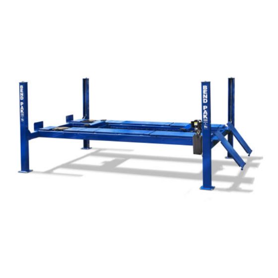
INSTALLATION AND OPERATION MANUAL
12,000 POUND
CAPACITY
FOUR-POST LIFT
SHIPPING DAMAGE CLAIMS
When this equipment is shipped, title passes to the
purchaser upon receipt from the carrier. Consequently,
claims for the material damaged in shipment must be made
by the purchaser against the transportation company at the
time shipment is received.
Forward this manual to all operators.
Failure to operate this equipment as
directed may cause injury.
Keep this operation manual near the
machine at all times. Make sure that
ALL USERS read this manual .
BE SAFE
Your new lift was designed and built with safety in
mind. However, your overall safety can be increased
by proper training and thoughtful operation on the part
of the operator. DO NOT operate or repair this
equipment without reading this manual and the
important safety instructions shown inside.
Santa Paula, CA. 93060, USA
Revised 4/27/04
Models:
HD-12LS
HD-12LSX
HD-12LSXE
1645 Lemonwood Dr.
Tel: 1-805-933-9970
Fax: 1-805-933-9160
Advertisement

Related Manuals for Bend-Pak HD-12LS

Summary of Contents for Bend-Pak HD-12LS
- Page 1 Failure to operate this equipment as directed may cause injury. Revised 4/27/04 INSTALLATION AND OPERATION MANUAL Models: 12,000 POUND CAPACITY HD-12LS FOUR-POST LIFT HD-12LSX HD-12LSXE Keep this operation manual near the machine at all times. Make sure that ALL USERS read this manual .
-
Page 2: Warranty
12,000 POUND CAPACITY FOUR POST ALIGNMENT LIFT This instruction manual has been prepared especially for you. Your new lift is the product of over 25 years of continuous research, testing and development and is the most technically advanced lift on the market today. READ THIS ENTIRE MANUAL BEFORE OPERATION BEGINS. -
Page 3: Important Safety Instructions
INTRODUCTION 1. Carefully remove the crating and packing report any shipping damage to the carrier and materials. CAUTION! Be careful when cutting make a notation on the delivery receipt. steel banding material as items may become loose and fall causing personal harm or injury. 3. -
Page 4: Tools Required
STEP 2 ( Floor Requirements ) LIFT CONCRETE MODEL REQUIREMENT HD-12LS 4” Min. Thickness This lift must be installed on a solid level HD-12LSX 4” Min. Thickness concrete floor with no more than 3-degrees of slope. Failure to do so could cause HD-12LSXE 4”... -
Page 5: Important Note
IMPORTANT NOTE The power unit must be installed at the location shown above. It is important to locate the POWER-SIDE runway ( with cylinder ) on the SAME SIDE as power unit location. Accessory rails on the side of each runway MUST be installed to the inside. - Page 6 STEP 3 ( Column & Cross Tube Installation ) 1. Locate the columns at their respective locations according to the chalk line layout. ( See above ) Pay attention to the power unit location. DO NOT BOLT columns down at this time. Use caution to prevent columns from falling over.
- Page 7 STEP 4 2. Manually clear the SLACK SAFETY lock devises on the end of each cross tube and slide the cross ( Anchoring The Columns ) tubes down until they rest on the safety lock position fourth down from the top of the column. (See Fig. 2) 1.
- Page 8 Fig. 9 Fig. 7 STEP 5 ( Runway Installation ) 4. Position the offside runway on top of the cross tubes with the utility rails located inside. The 1. Locate the runway with the cylinder attached offside runway is not bolted down and can be adjusted for different tread width vehicles.
- Page 10 STEP 7 STEP 8 ( Power Unit Installation ) ( Routing Hydraulic Hoses ) 1. Mount the power unit to the mounting bracket 1. Install the two 90 degree hydraulic fittings to the using the 5/16” x 3/4” hex bolts and nylon nuts POWER PORT and RETURN PORT of the power then fill the reservoir with 15 quarts of 10-WT unit and connect the hoses as described below.
- Page 11 STEP 9 ( Routing Airline ) Route the airline as shown below making sure to position the push button air valve with the INLET facing towards the AIR SOURCE and the OUTLET facing the direction of the COILED AIR HOSE. Pay careful attention to keep airline clear of any pinch points.
- Page 12 STEP 10 STEP 11 ( Power-Unit Start Up ) ( Lift Start Up ) 1. Make sure the power unit reservoir is full with 1. Have a certified electrician run 208 - 230 volt 15 quarts of 10-WT hydraulic oil or Dexron-III single phase 60 HZ power supply to motor.
- Page 13 NOTE: There will be some initial stretching of the cables in the beginning. It will be necessary to re-adjust the cables a week after first use, then every three to six months thereafter. 3. Run the lift up and down a few times to insure that the locks are engaging uniformly and that the Fig.
- Page 14 OPERATION: To Raise Lift; "Position vehicle tires in the center of each runway. "Set parking brake or use wheel chock to hold vehicle in position. "Before raising vehicle, be sure all personnel are clear of the lift and surrounding area. Pay careful attention to overhead clearances.
Need help?
Do you have a question about the HD-12LS and is the answer not in the manual?
Questions and answers