Table of Contents
Advertisement
Quick Links
SF10
Laser altimeter
! !
! !
! !
! !
! !
! !
! !
! !
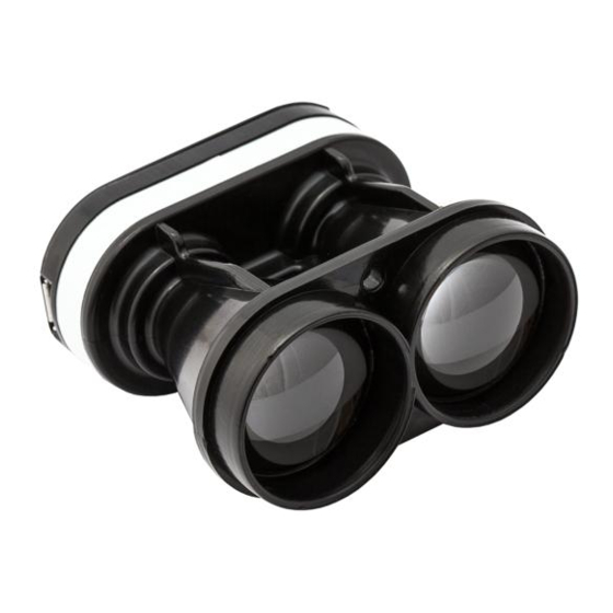
The SF10 is a compact, lightweight
laser altimeter for above-ground-
level altitude measurement from
small fixed wing or rotor craft.
!
The SF10 laser altimeter is ideal for
automated landings and precision
hovering.
!
The configurable features and
multiple hardware interfaces make
the SF10 easy to use with different
types of flight controller.
!
The SF10 laser altimeter uses a time-
of-flight system to make accurate
distance measurements to natural or
artificial surfaces.
!
SF10 Laser Altimeter - Product Manual - Revision 0
Product manual
Features:
!
•
Very compact and lightweight - 35 grams.!
!
•
Accurate AGL altitude measurement up to 50
!
meters on most natural and artificial
•
!
Fast update rate of 16 readings per second.!
•
Includes serial, I2C, USB and analog interfaces
!
with programmable capabilities.!
•
Easy to configure using the built-in menu and
!
LightWare Terminal software.!
•
!
Fully calibrated and ready to run.!
•
Accurate, reliable altitude measurements in
!
sunlight or dark conditions.!
•
Not affected by: speed; wind; changes in
barometric pressure; noise; ambient light; terrain
or air temperature.
1
! of !
10
surfaces.!
!
© LightWare Optoelectronics (Pty) Ltd, 2014
Advertisement
Table of Contents

Summary of Contents for Lightware SF10
- Page 1 Not affected by: speed; wind; changes in distance measurements to natural or barometric pressure; noise; ambient light; terrain or air temperature. artificial surfaces. ! of ! SF10 Laser Altimeter - Product Manual - Revision 0 © LightWare Optoelectronics (Pty) Ltd, 2014...
-
Page 2: Table Of Contents
Information found in this document is used entirely at the reader’s own risk and whilst every effort has been made to ensure its validity neither LightWare Optoelectronics (Pty) Ltd nor its representatives make any warranties with respect the accuracy of the information contained herein. -
Page 3: Overview
USB port. The SF10 works by measuring the time it takes for a very short flash of laser light to travel to the ground and back again. The accuracy of the measurement is not affected by the colour or texture of the ground nor the angle of incidence of the laser beam. -
Page 4: Quick Start Guide
0 … 10 Sets the damping coefficient to smooth the readings 7. Once you have confirmed your settings, make sure the SF10 is measuring correctly then click the “Disconnect” icon and disconnect the USB cable from the SF10. 8. There are several interface options available on the main connector. These connections are used to integrate the SF10 into your system and details of all the options are explained later in this document. -
Page 5: Making Connections To The Sf10
3. Making connections to the SF10 The SF10 gets power from either a regulated +5 V DC supply on the main connector or via the USB port when it is connected to a PC. There are a number of digital and analog interfaces on the main connector and either one or a combination of interfaces may be connected to a host controller. -
Page 6: Figure 5 :: Analog Voltage Connections
“slave” mode and uses 3.3 V logic levels. The I2C address can be set through the USB menu system. The host controller acts as the I2C “master” and sends the address to the SF10 as an 8 bit value. The SF10 then returns the altitude as a 16 bit integer. The maximum delay between receiving the address and returning the altitude is 25 ms. -
Page 7: Menu Options
Serial port baud rate (9600 … 115200) The serial port transmits a serial string of ASCII encoded data from the SF10 to the host controller. The baud rate of transmission is selected by menu item <A> and toggles through the standard baud rates from 9600 to 115200. By default, there is 1 stop bit and no parity or handshaking on this serial port. -
Page 8: Figure 9 :: Altitude Represented By Distance (Serial / I2C) And Analog Voltage
0.00 meter to +10.00 meters and this value is subtracted from the altitude reading before it is made available on any of the interfaces. The ground offset can be used to compensate for the mounting position of the SF10 in the airframe, where distance readings may best be interpreted from a suitable point on the landing gear, rather than from the front face of the SF10. -
Page 9: Instructions For Safe Use
Make sure that the SF10 is switched OFF before looking into the lenses. The SF10 should be mounted using the four holes provided in the circuit board. Do not hold or clamp the lens tubes as this may cause damage and adversely affect the laser safety rating. -
Page 10: Appendix A :: Specifications
Appendix B :: Dimensions Figure 11 :: Dimension drawings of the SF10/A Revision history Version Date Authors Comments Rev 0 2014/07/12 First edition of ! SF10 Laser Altimeter - Product Manual - Revision 0 © LightWare Optoelectronics (Pty) Ltd, 2014...


Need help?
Do you have a question about the SF10 and is the answer not in the manual?
Questions and answers