Table of Contents
Advertisement
Quick Links
Advertisement
Table of Contents

Related Manuals for Technimount System BRACKET PRO 75 Series


Summary of Contents for Technimount System BRACKET PRO 75 Series
- Page 1 BRACKET PRO SERIE ® USER GUIDE...
-
Page 2: Copyright
Rights Reserved. No part of this publication may be reproduced, transmitted, transcribed, stored in a retrieval system, or translated into any language in any form or by any means without the written permission of Technimount System or its affiliate companies. -
Page 3: Contact Information
Contact Information OFFICE ADDRESS Technimount E.M.S. Holding Inc. 3770 Jean Marchand Street, Suite 100-C Quebec (QC) G2C 1Y6 Canada info@technimount.com www.technimount.com T + 1 888.639.2758 F + 1 855.339.6351 NOTE: For any issues with your Technimount product, its components, or for any technical questions during the installation or maintenance processes, please send an email to techsupport@technimount.com Please have the serial number of your Technimount product available (as shown in the figure below) when calling... -
Page 4: Table Of Contents
Table of Contents COPYRIGHT ................................2 CONTACT INFORMATION ............................3 INTRODUCTION ..............................6 Purpose of the Document ............................6 Product Description ..............................6 Intended use of the Product ............................6 Possible Mounting Options for the Bracket Pro Serie 75 ..................7 Symbols and Definitions ...............................8 Warning / Caution / Note .............................9 Product Illustration ..............................10 BRACKET Pro Serie 75 ............................10 Front View ..................................10... - Page 5 Table of Contents Replacement Parts ...............................35 WARRANTY ................................36 Warranty Policy ................................36 LIMITED RESPONSIBILITY AND WARRANTY........................36 INTERNATIONAL WARRANTY CLAUSE ..........................36 Return Policy ................................37 Prior to 30 Days ..............................37 Prior to 45 Days ..............................37 Prior to 60 Days ..............................37 Return Authorization ..............................37 Damaged Merchandise ..............................38 Claim Process ................................38 Required Information ............................38...
-
Page 6: Introduction
Introduction PURPOSE OF THE DOCUMENT This User Guide is designed to assist you with the installation, operation and maintenance of the Technimount Bracket Pro Serie 75 for the Tempus LS monitor from Philips. PRODUCT DESCRIPTION The Bracket Pro Serie 75 Mounting System is the only universal solution to mount the Tempus LS monitor from Philips in different applications such as, on surface, floor, cot/stretcher and wall systems. -
Page 7: Possible Mounting Options For The Bracket Pro Serie 75
Introduction POSSIBLE MOUNTING OPTIONS FOR THE BRACKET PRO SERIE 75 Safety MD Transporter Safety Arm System Wall Mount System Standard Surface Base (Ground Ambulance in Europe) Return To Table of Contents www.technimount.com BP75 UG 202110-01... -
Page 8: Symbols And Definitions
Introduction SYMBOLS AND DEFINITIONS SYMBOL DESCRIPTION Warning and Caution, special attention is required. Consult accompanying documents Safe working load symbol and Load balance symbol Pinch Point Return To Table of Contents BP75 UG 202110-01 www.technimount.com... -
Page 9: Warning / Caution / Note
Introduction WARNING / CAUTION / NOTE The word warning, caution, or note carry special meaning and should be carefully reviewed. SYMBOL DESCRIPTION Warning Alerts the reader about a situation which, if not avoided, could result in death or serious injury. It may also describe potential serious adverse reactions and safety hazards. -
Page 10: Product Illustration
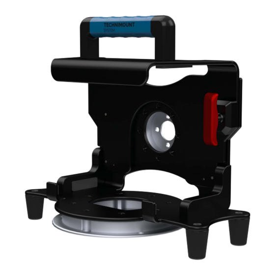
Introduction PRODUCT ILLUSTRATION BRACKET PRO SERIE 75 Front View Main assembly is attached to the Tempus LS with a quick release and locking mechanism Rubber pads to protect the medical device from scratches Standard Bottom Disc compatible with all of Technimount’s Acetal feet to protect the mounting solutions disc and Tempus LS when... -
Page 11: Back View
Introduction PRODUCT ILLUSTRATION (CONTINUED) BRACKET PRO SERIE 75 (CONTINUED) Back View Technimount molded Bracket is made polyurethane transport handle from high-density aluminum with black- anodized finish Anti-Rotation Micro Disc is used for vertical support on different wall or arm systems Return To Table of Contents www.technimount.com BP75 UG 202110-01... -
Page 12: Specifications
Introduction SPECIFICATIONS Product Name Bracket Pro Serie® 75 Product Description Dual disc bracket mounting system to secure the Philips® Tempus® LS on surfaces, cots/stretchers, and wall systems in emergency vehicles Compatibility of Medical Device* Tempus® LS from Philips® Environment of Usage EMS/CCT (Ground &... - Page 13 The end user and administrator are responsible to validate regulations and standards for safety in their region, in order to comply with applicable safety regulations. Technimount System is not responsible to inform the end user and/or administrator of applicable legislation for safety in their area.
-
Page 14: Summary Of Safety Precautions
9 It is the responsibility of the operator of the Bracket or any of its options, to ensure equipment being used with the Technimount products meets the installation specifications. Injury may result if non-compatible products are used with Technimount System products. 9 Do not attempt to operate, install or remove the equipment while mobile. Ensure that installation and removal of equipment is done while vehicle or aircraft is immobilized. - Page 15 9 Regularly inspect all components on the equipment for any issue and loose screws, bolts and nuts. 9 Never install the mount into or on other similar mounting systems or brackets without written confirmation by Technimount System as these different systems may be from other brands or models and may not be compatible with Technimount Systems.
-
Page 16: Installation Guide
NOTE 9 Electrical tools are not recommended, as there is a potential risk of damage to the threads. 9 Technimount System provides screws with Nylon Patch for the installation of the locking assembly block. Return To Table of Contents BP75 UG 202110-01... -
Page 17: Installation Of The Bracket Onto The Tempus Ls Monitor
Installation Guide INSTALLATION OF THE BRACKET ONTO THE TEMPUS LS MONITOR 1. The Bracket Pro Serie 75 is designed to be installed on the Tempus LS monitor from Philips. 2. To install the Tempus LS monitor, pull the red handle and raise the top part until it locks into the top position. - Page 18 Installation Guide INSTALLATION OF THE BRACKET ONTO THE TEMPUS LS MONITOR (CONTINUED) 4. Install the Tempus LS into the Main Assembly. 5. Pull the red handle and lower the top part until it locks into the bottom platform. 6. The Tempus LS monitor is ready for EMS transport. Return To Table of Contents BP75 UG 202110-01 www.technimount.com...
-
Page 19: Installation Of The Bracket Onto Tempus Ls Monitor With Smart Mount
Installation Guide INSTALLATION OF THE BRACKET ONTO TEMPUS LS MONITOR WITH SMART MOUNT 1. The Bracket Pro Serie® 75 Smart Mount is designed to be installed on the Philips Tempus LS monitor. 2. To install the Tempus LS Smart Mount monitor, pull the Red Quick Release Mechanism and raise the top part until it locks into the top position. - Page 20 Installation Guide INSTALLATION OF THE BRACKET ONTO THE TEMPUS LS MONITOR WITH SMART MOUNT (CONTINUED) 4. Install the Smart Mount into the Main Assembly. 5. Align screw holes. 6. Install the four Stainless Steel Flat Head Philips Screws, 10-32 X 9/16 in. 7.
- Page 21 Installation Guide INSTALLATION OF THE BRACKET ONTO THE TEMPUS LS MONITOR WITH SMART MOUNT (CONTINUED) Lower the top part until it locks into the bottom position. 10. The Tempus LS Smart Mount monitor is ready for EMS transport. Return To Table of Contents Return To Table of Contents www.technimount.com BP75 UG 202110-01...
-
Page 22: Operation Guide
Operation Guide GENERAL OPERATING GUIDELINES FOR THE SAFETY MD TRANSPORTER 9 Use the Safety MD Transporter only as described in the User Guide. 9 Read all the labels and instructions on the product before using the Safety MD Transporter. 9 Always inspect the Micro Base and the Safety MD Transporter for any issue or damage before every use. -
Page 23: Operating The Bracket On The Safety Md Transporter
Operation Guide OPERATING THE BRACKET ON THE SAFETY MD TRANSPORTER INSTALLING THE BRACKET ONTO THE SAFETY MD TRANSPORTER 1. Only Technimount brackets with an Anti-Rotation Micro Disc on the back can be inserted into the Micro Base located on the Safety MD Transporter. 2. -
Page 24: Rotating The Bracket On The Safety Md Transporter
Operation Guide OPERATING THE BRACKET ON THE SAFETY MD TRANSPORTER (CONTINUED) INSTALLING THE BRACKET ONTO THE SAFETY MD TRANSPORTER (CONTINUED) 4. A Bracket Pro Serie 75 installed on the Safety MD Transporter. ROTATING THE BRACKET ON THE SAFETY MD TRANSPORTER 1. -
Page 25: Removing The Bracket With The Medical Device From The Safety Md Transporter
Operation Guide OPERATING THE BRACKET ON THE SAFETY MD TRANSPORTER (CONTINUED) REMOVING THE BRACKET WITH THE MEDICAL DEVICE FROM THE SAFETY MD TRANSPORTER 1. To remove the bracket from the Safety MD Transporter, press the Red Quick Release Mechanism located on the back Micro Base. 2. -
Page 26: General Operating Guidelines For The Safety Arm System
Operation Guide GENERAL OPERATING GUIDELINES FOR THE SAFETY ARM SYSTEM 9 Use the Safety Arm System only as described in its User Guide. 9 Read all the labels and instructions on the product before using the Safety Arm System. 9 Always inspect the Clamp Block, Safety Pin, Lock Pin, and Standard Surface Base before every use. -
Page 27: Operating The Bracket On The Safety Arm System
Operation Guide OPERATING THE BRACKET ON THE SAFETY ARM SYSTEM INSTALLING THE BRACKET ON THE STANDARD SURFACE BASE 1. Only Technimount brackets with a Standard Bottom Disc can be inserted onto the Standard Surface Base located on the Safety Arm System. 2. -
Page 28: Removing The Bracket From The Standard Surface Base
Installation Guide OPERATING THE BRACKET ON THE SAFETY ARM SYSTEM (CONTINUED) REMOVING THE BRACKET FROM THE STANDARD SURFACE BASE 1. To remove the bracket from the Standard Surface Base, press the Red Quick Release Mechanism located on the front of the Standard Surface Base. -
Page 29: Part Numbers
Part Numbers KITS AND OTHER OPTIONS DESCRIPTION PART NUMBER Bracket 321-10-LS-RDT 553-20-AB-WA Wall Mount 554-20-AB-FL Floor Mount 100-20-UN Standard Surface Base Several Models Available, Safety Arm System refer to Customer Service Different Models Available, Safety MD Transporter refer to Customer Service WARNING Do not modify any components of these system. -
Page 30: Maintenance Guide
Maintenance Guide CLEANING THE BRACKET SYSTEM CLEANING PROCESS WARNING Follow your EMS service's protocol or medical device manufacturer's User Guide for the recommended cleaning procedure of your medical devices. Cleaning procedure below does NOT provide recommendations for cleaning of the medical device. -
Page 31: Removal Of Iodine Compounds
Maintenance Guide CLEANING THE BRACKET SYSTEM (CONTINUED) CLEANING SOLUTIONS CONTINUED WARNING 9 Some cleaning products are corrosive in nature and may cause damage to the product if used improperly. 9 If the products described are used to clean the equipment, the Bracket and components must be rinsed with clean water and thoroughly dried following cleaning. -
Page 32: Inspection Process And Schedule
Maintenance Guide INSPECTION PROCESS AND SCHEDULE MAINTENANCE PROGRAM The following inspection routine and schedule is intended as a general guide for preventive maintenance of the Bracket. Factors such as weather, environment, geographical location, and individual usage will necessitate different maintenance. If you are unsure as to how to perform these maintenance inspections or at what interval to perform these inspections, please contact your Technical Support Team at techsupport@technimount.com. -
Page 33: Inspection And Maintenance Record
Maintenance Guide INSPECTION AND MAINTENANCE RECORD PREVENTIVE MAINTENANCE DATE TIME PERFORMED Return To Table of Contents www.technimount.com BP75 UG 202110-01... -
Page 34: Training Record
Maintenance Guide TRAINING RECORD TRAINING DATE TRAINING METHOD USER GUIDE, IN-SERVICE, BASIC TRAINING TRAINEE NAME IN-CLASS, TRAINING UPDATE ETC. Return To Table of Contents BP75 UG 202110-01 www.technimount.com... -
Page 35: Replacement Parts
Maintenance Guide REPLACEMENT PARTS The parts and accessories listed are all currently available for purchase. Some of the parts identified on the assembly drawing parts in this user guide may not be individually available for purchase. Please call Technimount Customer Service : +1.888.639.2758 or at customerservice@technimount.com for availability and pricing. -
Page 36: Warranty
SET FORTH HEREIN. THERE IS NO WARRANTY OF MERCHANTABILITY AND THERE ARE NO WARRANTIES OF FITNESS FOR ANY PARTICULAR PURPOSE. IN NO EVENT SHALL TECHNIMOUNT SYSTEM BE LIABLE HEREUNDER FOR INCIDENTAL OR CONSEQUENTIAL DAMAGES ARISING FROM OR IN ANY MANNER RELATED TO SALES OR USE OF ANY SUCH EQUIPMENT. -
Page 37: Return Policy
▪ Product must be unused, undamaged and in its original packaging ▪ The product return request must be provided in writing and it must be approved by TECHNIMOUNT SYSTEM prior to returning the product ▪ Returns will not be approved on modified or damaged item ▪... -
Page 38: Damaged Merchandise
Warranty DAMAGED MERCHANDISE ICC Regulations require that claims for damaged merchandise must be made with the carrier within fifteen (15) days of receiving merchandise. DO NOT ACCEPT DAMAGED SHIPMENTS UNLESS SUCH DAMAGE IS NOTED ON THE DELIVERY RECEIPT AT THE TIME OF RECEIPT. Upon prompt notification, TECHNIMOUNT will file a freight claim with the appropriate carrier for damages incurred. -
Page 39: Sae Certification
SAE Certification Return To Table of Contents www.technimount.com BP75 UG 202110-01... - Page 40 Safety and flexibility where it matters most Technimount E.M.S. Holding Inc. 3770 Jean Marchand Street, Suite 100-C Quebec (QC) G2C 1Y6 Canada T + 1 888.639.2758 F + 1 855.339.6351 technimount.com info@technimount.com © 2021 Technimount E.M.S. Holding Inc. - All Rights Reserved Printed in Canada...
Need help?
Do you have a question about the BRACKET PRO 75 Series and is the answer not in the manual?
Questions and answers