
Related Manuals for USAVision UVS-ABD1300


Summary of Contents for USAVision UVS-ABD1300
- Page 1 Quick Start Guide UVS-ABD1300 Eyeball IP Dome Before attempting to connect or operate this product, UVSABDV10-QG-A please read these instructions carefully and save this manual for future use.
- Page 2 USA Vision Systems Inc. 9235 Research Drive, Irvine, CA 92618, USA Tel: +1-949-583-1519 Fax: +1-949-583-1522 http://www.usavisionsys.com Trademarks used in this manual: USAVision and the USAVision logo are trademarks of USA Vision Systems Inc. Windows is the registered trademark of Microsoft Corporation. January 2017...
-
Page 3: Table Of Contents
Contents Note for Connecting to GV-VMS / DVR / NVR........ii Note for Installing Camera Outdoor............iii 1. Introduction ..................1 1.1 Packing List ......................1 1.2 Optional Accessories ..................... 2 1.3 Overview........................ 2 2. Installation ..................4 3. Waterproofing the Cable ..............7 4. Accessing the Camera ..............9 4.1 Looking Up the Dynamic IP Address.............. -
Page 4: Note For Connecting To Gv-Vms / Dvr / Nvr
Note for Connecting to GV-VMS / DVR / NVR The Eyeball Dome is designed to work with GV-VMS / DVR / NVR, a video management system. Once the camera is connected to the GV-VMS / DVR / NVR, the resolution set on the GV-VMS / DVR / NVR will override the resolution set on the camera’s Web interface. -
Page 5: Note For Installing Camera Outdoor
Note for Installing Camera Outdoor When installing the camera outdoor, be sure that: The camera is set up above the junction box to prevent water from entering the camera along the cables. Any power, audio and I/O cables are waterproofed using waterproof silicon rubber or the like. -
Page 6: Introduction
Introduction 1. Introduction Welcome to the Eyeball IP Dome Quick Start Guide. In the following sections, you will learn the basic installations and configurations. For details, see its User’s Manual. 1.1 Packing List Eyeball Dome Waterproof Rubber Set ... -
Page 7: Optional Accessories
1.2 Optional Accessories Optional accessories can expand the capabilities and versatility of your camera. Contact your dealer for more information. Model Number Name Details GV-Mount211 Wall Mount Bracket Dimensions: 233 x 126 x 126 mm (9.2” x 5” x 5”) Weight: 0.92 kg (2.0 lb) Dimensions: Φ126 x 36 mm GV-Mount212... -
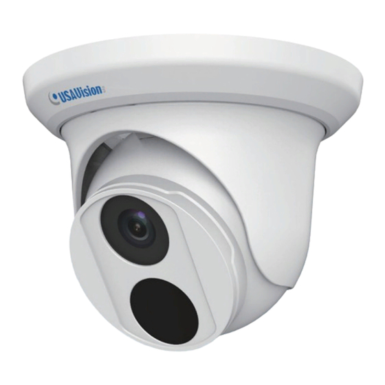
Page 8: Overview
Introduction 1.3 Overview Description Bottom ring Housing Lens Infrared LED Power connector (DC 12 V) An optional power adapter is required. Ethernet connector / PoE... -
Page 9: Installation
2. Installation The Eyeball Dome is designed for outdoors. With the standard package, you can install the camera on the ceiling. Or you can purchase optional mounting accessories to mount the camera on a wall. Below are the instructions for Ceiling Mount. There are two kinds of Ceiling Mount: Concealed Installation and Open Installation. - Page 10 Installation Remove the bottom ring by turning it anticlockwise. Connect the cables and then secure the camera. Adjust the monitoring direction.
- Page 11 Mount the bottom ring. For Open Installation Lead the cables out from the open slot on the bottom ring before screwing the camera to the ceiling as shown in step 4 in For Concealed Installation. Note: You can optionally purchase GV-Mount211 for Wall Bracket Mount. For details, see its User’s Manual.
-
Page 12: Waterproofing The Cable
Waterproofing the Cable 3. Waterproofing the Cable Waterproof the Ethernet cable by using the supplied waterproof rubber set. Attach the seal ring to the RJ-45 plug. Seal ring Insert the waterproof components through the Ethernet cable as shown below. 2 Insert in order Insert the cylindrical waterproof ring into waterproof bolt. - Page 13 Insert the cable into the RJ-45 plug and screw the waterproof bolt in. Screw in the waterproof bolt lid. Bolt lid Finish the waterproof Installation.
-
Page 14: Accessing The Camera
Accessing the Camera 4. Accessing the Camera 4.1 Looking Up the Dynamic IP Address By default, when the camera is connected to LAN with a DHCP server, it is automatically assigned with a dynamic IP address. Follow the steps below to look up its IP address. Note: The computer you use to configure the IP address must be under the same LAN with your camera. - Page 15 4. The login page appears. 5. For the first time accessing the Web interface, download and install the plug-in. 6. Type the default ID and password admin and click Login to log in.
-
Page 16: Configuring The Ip Address
Accessing the Camera 4.2 Configuring the IP Address If the camera is connected to LAN without a DHCP server, the default IP address will be 192.168.0.10. Follow the steps below to modify the IP address to avoid IP conflict with other GV-IP devices on the same LAN. -
Page 17: The Web Interface
5. The Web Interface Once you log in the Web interface, you will see the live view as shown below. No. Name Function Set the display ratio of the image. Scale: display images by 16:9. Proportional Stretch: display images by window size. ... - Page 18 The Web Interface Digital Zoom Start or stop digital zoom. Reset the packet loss rate to zero. Display packet loss rate and bit rate information in the bottom. Note: The paths for saving snapshots and local recordings are set in System Configuration. The buttons (No.
-
Page 19: Upgrading System Firmware
6. Upgrading System Firmware We periodically release the updated firmware on the website. To load the new firmware into the camera, follow the instructions below. 1. At the top of the Web interface, click Setup. 2. In the left menu, select System and select Maintenance. This page appears. 3. -
Page 20: Restoring To Factory Default
Restoring to Factory Default 7. Restoring to Factory Default You can restore the camera to factory default settings using the Web interface. 1. At the top, click Setup. 2. In the left menu, select System and select Maintenance. 3. Under the Config Management section, click the Default button. Note: There is no default button on the camera.
Need help?
Do you have a question about the UVS-ABD1300 and is the answer not in the manual?
Questions and answers